Table of Contents
Advertisement
Quick Links
Instructions
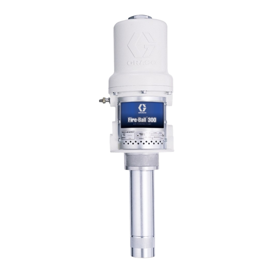
5:1 Fire-Ball
Pump
For pumping non-corrosive and non-abrasive greases and lubricants only.For professional
use only.
Model No. 203872, 203857, 204254,
222087, 203876
900 psi (6.2 MPa, 62 bar) Maximum Working Pressure
180 psi (1.2 MPa, 12 bar) Maximum Air Input Pressure
Important Safety Instructions
Read all warnings and instructions in this
manual. Save these instructions.
®
300
306518ZAE
EN
Advertisement
Table of Contents

Subscribe to Our Youtube Channel
Related Manuals for Graco 5:1 Fire-Ball 300


Summary of Contents for Graco 5:1 Fire-Ball 300
- Page 1 Instructions ® 5:1 Fire-Ball Pump 306518ZAE For pumping non-corrosive and non-abrasive greases and lubricants only.For professional use only. Model No. 203872, 203857, 204254, 222087, 203876 900 psi (6.2 MPa, 62 bar) Maximum Working Pressure 180 psi (1.2 MPa, 12 bar) Maximum Air Input Pressure Important Safety Instructions Read all warnings and instructions in this manual.
-
Page 2: Table Of Contents
Dimensions ......15 Graco Standard Warranty ....16... -
Page 3: Warnings
Warnings Warnings The following warnings are for the setup, use, grounding, maintenance, and repair of this equipment. The exclama- tion point symbol alerts you to a general warning and the hazard symbols refer to procedure-specific risks. When these symbols appear in the body of this manual or on warning labels, refer back to these Warnings. Product-specific hazard symbols and warnings not covered in this section may appear throughout the body of this manual where applicable. -
Page 4: Installation
Installation Installation Grounding To maintain grounding continuity when flushing or relieving pressure: hold metal part of the valve firmly to the side of a grounded metal pail, then trigger the gun/valve. To ground the pump: remove the ground screw (Z) and The equipment must be grounded to reduce the risk insert through the eye of the ring terminal at end of the of static sparking and electric shock. -
Page 5: System Accessories
Installation 1. Install the pump on the drum cover so that the 1. Install a pump runaway valve (D) to shut off the air pump’s fluid intake is 1/2 inch. (13 mm) off the bot- to the pump if the pump accelerates beyond the tom of the drum. -
Page 6: Operation
Operation Operation Pressure Relief Procedure 5. If your pump accelerates quickly or is running too fast, stop it immediately and check the fluid supply. If the supply container is empty and air has been Follow the Pressure Relief Procedure whenever pumped into the lines, prime the pump and lines you see this symbol. -
Page 7: Troubleshooting
Troubleshooting Troubleshooting 1. Follow Pressure Relief Procedure, page 6, before checking or repairing gun. 2. Check all possible problems and causes before dis- assembling gun. Problem Cause Solution Inadequate air supply pressure or Increase air supply and/or clear restricted air lines restriction Closed or clogged valves Open and/or clear... -
Page 8: Service
Service Service Displacement Pump Service 11. Clamp the flats of the fluid piston (110) in a vise, and torque the displacement rod (8) to the piston to 40 to 60 ft-lbs (54 to 81 N.m). 12. Clamp the air motor base (5) in a vise horizontally by closing the vise jaws on the flange. - Page 9 Service 6. Using wrenches on the flats of the displacement rod (8) and on the flats of the fluid piston (110), unscrew the fluid piston from the displacement rod. Remove the ball (111) from the end of the displacement rod, and remove the packing o-ring (104) from the fluid piston.
- Page 10 Service Reassembly (1) and the piston seat when the inlet valve is open. See the Cutaway View, F . 4. 1. Clean all the parts carefully in a compatible solvent, and inspect for wear or damage. Use all the repair NOTE: Adjust the distance between the inlet valve pop- kit parts during reassembly, and replace other parts pets and the piston seat by turning the top valve nuts...
- Page 11 Service 20. Grip the trip rod (11) with padded pliers, screw the 23. Clamp the flats of the fluid piston (11) in a vise, and cylinder cap (29) onto the trip rod, push the cylinder torque the displacement rod (8) to the piston to 40 to cap nut down, and screw it into the top of the cylin- 60 ft-lbs (54 to 81 N.m).
-
Page 12: Parts
Parts Parts Air Motor Pump 112* 118b 118a 104* 108* 114, 115, 116, or 117 18** **20 **19 Lips face down. 306518ZAE... - Page 13 Parts Model 203857, Series R, 55 gal. Ref. Part Description Qty. 158360 YOKE, rod, trip Includes items 101 to 114 158362 PIN, toggle Model 203872, Series R, 16 gal. O-RING, nitrile rubber Includes items 101 to 113 and 115 160623 ARM, toggle 158364 ROCKER, toggle Model 203876, Series R, Universal...
-
Page 14: Technical Data
Technical Data Technical Data ® 5:1 Fire-Ball 300 Pumps Metric Maximum fluid working pressure 900 psi 6.2 MPa, 62 bar Fluid pressure ratio Air pressure operating range* 40 to 180 psi 0.28 to 1.2 MPa, 2.8 to 12 bar Maximum air consumption 13 ft /minute for first gpm 0.096 m... -
Page 15: Dimensions
Dimensions Dimensions Model 203876, Series N, Overall length 20.7 in (526 mm) Model 203857, Series N, Overall length 45.6 in (1158 mm) Model 203872, Series N, Overall length 38.1 in (968 mm) Model 204254, Series S, Overall length 49.9 in (1267 mm) Model 222087, Series E, Overall length 59.9 in (1521 mm) grounding screw... -
Page 16: Graco Standard Warranty
With the exception of any special, extended, or limited warranty published by Graco, Graco will, for a period from the date of sale as defined in the table below, repair or replace equipment covered by this warranty and determined by Graco to be defective.
Need help?
Do you have a question about the 5:1 Fire-Ball 300 and is the answer not in the manual?
Questions and answers