
Related Manuals for CTC Union IGS-804SM-SE-8PH


Summary of Contents for CTC Union IGS-804SM-SE-8PH
- Page 1 Quick Installation Guide IGS-804SM-SE-8PH IGS-804SM-SE-8PHE Industrial 8 x 10/100/1000Base T(X) + 4 x 100/1000Base-X SFP Slots with SyncE & 4 x PoE+ Managed Ethernet Switches (Hardened) sales@ctcu.com...
- Page 2 8F, No. 60 Zhouzi St., Neihu, Taipei 114, Taiwan T +886-2-26591021 F +886-2-26590237 E sales@ctcu.com H www.ctcu.com 2020 CTC Union Technologies Co., LTD. All trademarks are the property of their respective owners. Technical information in this document is subject to change without notice.
- Page 3 CTC Union Technologies makes no warranty, representation, or guarantee regarding the suitability of its products for any particular purpose, nor does CTC Union assume any liability arising out of the application or use of any product and specifically disclaims any and all liability, including without limitation any consequential or incidental damages.
-
Page 4: Table Of Contents
Table of Contents Introduction .................. 5 Package List ................. 5 Features ..................5 Access to Command Line Interface (CLI) ........6 ..................6 ONSOLE ONNECTION /SSH C ..................7 ELNET ONNECTION Access to Web-Based Management Interface ......8 Specifications ................9 .................... -
Page 5: Introduction
Introduction IGS-804SM-SE-8PH(E) models are industrial grade managed Gigabit Sync Ethernet switches with PoE+ function that provide stable and reliable Ethernet transmission. Housed in rugged DIN rail or wall mountable enclosures, these switches are designed for harsh environments, such industrial networking... -
Page 6: Access To Command Line Interface (Cli)
Access to Command Line Interface (CLI) IGS-804SM-SE-8PH(E) models are Sync Ethernet managed Gigabit switches with PoE function. Initial configuration (assignment of IP address) may be accomplished via the RS-232 console and a PC or laptop running terminal emulation software or via RJ45 Ethernet port running Telnet or SSH. -
Page 7: Telnet/Ssh Connection
Telnet/SSH Connection To use Command Line Interface (CLI), you can also choose to access the device through a Telnet/SSH connection via TCP/IP network over Ethernet ports. For initial operation, use the default TCP/IP settings (10.1.1.1) to login to the device. Default TCP/IP settings: IP Address: 10.1.1.1 Subnet Mask: 255.255.255.0... -
Page 8: Access To Web-Based Management Interface
Access to Web-Based Management Interface To enter the web-based management interface for the first time or after returning the device back to factory defaults, input the default IP 10.1.1.1 address “ ” in your web browser. Then, a standard login prompt will appear depending on the type of browser used. -
Page 9: Specifications
Specifications Ethernet Interface • Standards: IEEE802.3 (10Base-T), 802.3u (100Base-TX), 802.3ab (1000Base-T) • RJ-45 (shielded) Ports: 8 ports • Speed: 10/100/1000M (Auto) Optical Interface • Standards: IEEE802.3u (100Base-FX), 802.3z (1000Base-X) • SFP-Based Slots: 4 slots • Speed: 100/1000M (Manual) Switch Features •... -
Page 10: Mechanical
• Dimensions: 116 mm (D) x 91 mm (W) x 157 mm (H) • Mounting: DIN-Rail, Wall Mount (Optional) • Weight: 760 g Environmental • Operating Temperature: -10°C~60°C (IGS-804SM-SE-8PH); -40°C~75°C (IGS-804SM-SE-8PHE) • Storage Temperature: -40°C~85°C • Humidity: 5%~95% (Non-condensing) Certifications •... -
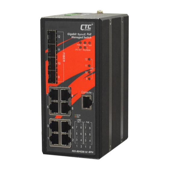
Page 11: Panels
Panels Figure 2. Top Panel Figure 1. Front Panel Description UTP/PoE RJ-45 ports Fiber optic SFP slots Power, Ring, CPU ACT, Fault LED indicators Link/ACT, Speed & PoE LED indicators for UTP RJ-45 port Console port (RJ-45 to DB-9) Link/ACT LED indicators for fiber optic ports Terminal block Earth grounding connection... -
Page 12: Lan And Fiber Ports
LAN and Fiber Ports IGS-804SM-SE-8PH(E) models have 8 UTP LAN ports (labeled 1~8) and 4 fiber ports (SFP based, labeled Fiber 9~12) on the front panel. The LAN ports that utilize shielded RJ-45 connectors support 10/100/1000M; while the fiber SFP ports support 100/1000M. -
Page 13: Console Port
CONSOLE Port The RJ-45 port labeled “CONSOLE” is an RS-232 terminal port for local management. These models use a “light” CLI (Command Line Interface) in addition to a user friendly Web interface and industry standard SNMP. One RJ-45 to DB-9 cable is provided with this device. CONSOLE port pinouts and RS-232 DB-9 connector are illustrated below together with RJ-45 to DB-9 signal mapping information. -
Page 14: Recommended Power, Alarm, Ground Wiring Scheme
Recommended Power, Alarm, Ground Wiring Scheme DC Power Connection A removable terminal block on the top panel provides both power and alarm connections. Power can be provided through the dual inputs from separate sources (PWR1 & PWR2). One power supply is enough to power up the device. -
Page 15: Alarm Relay Connection
Alarm Relay Connection The alarm relay contact can be wired into an alarm circuit which senses an alarm condition when the contact is broken. The alarm relay is normally closed when there is no alarm condition. The alarm conditions are user programmable through management to include power, link faults or other fault conditions. -
Page 16: Led Indicators
LED Indicators Color Status Definition Power is connected and active at the PWR1/PWR2 input terminal PWR1/ Green PWR2 connection. PWR1/PWR2 is not connected. When one or more of the programmable alarm conditions is active. Fault Amber Normal operation without faults. Alarm conditions are all disabled. -
Page 17: Installation
Installation The switch can be mounted on the wall or installed in DIN rail depending on your installation needs. When installing the wall-mounting bracket (optional accessory) and DIN rail bracket, be sure to correctly align the orientation pin. Figure 10. DIN Rail Figure 11. - Page 18 Version Date Description 2020/12/25 Use new document format...
Need help?
Do you have a question about the IGS-804SM-SE-8PH and is the answer not in the manual?
Questions and answers