
Related Manuals for CTC Union IGS-600-4PH24


Summary of Contents for CTC Union IGS-600-4PH24
- Page 1 Quick Installation Guide IGS-600-4PH24 IGS-600-4PHE24 Industrial Grade Gigabit Ethernet PoE Switches sales@ctcu.com...
- Page 2 8F, No. 60 Zhouzi St., Neihu, Taipei 114, Taiwan T +886-2-26591021 F +886-2-26590237 E sales@ctcu.com H www.ctcu.com 2020 CTC Union Technologies Co., LTD. All trademarks are the property of their respective owners. Technical information in this document is subject to change without notice.
- Page 3 CTC Union Technologies makes no warranty, representation, or guarantee regarding the suitability of its products for any particular purpose, nor does CTC Union assume any liability arising out of the application or use of any product and specifically disclaims any and all liability, including without limitation any consequential or incidental damages.
-
Page 4: Table Of Contents
Table of Contents Introduction .................. 5 Package List ................. 5 Features ..................5 Specifications ................6 .................... 6 THERNET NTERFACE ....................6 WITCH EATURES ..................6 OWER OVER THERNET ......................6 OWER ...................... 6 ECHANICAL ....................7 NVIRONMENTAL ....................7 ERTIFICATIONS MTBF (MIL-HDBK-217) .................. -
Page 5: Introduction
Introduction IGS-600-4PH(E)24 are non-managed industrial grade Gigabit PoE (Power over Ethernet) switches that provide stable and reliable Ethernet transmission. Housed in rugged DIN rail or wall mountable enclosures, these switches are designed for harsh environments, such as industrial networking and intelligent transportation systems (ITS) and are also suitable for many military and utility market applications where environmental conditions exceed commercial product specifications. -
Page 6: Specifications
Specifications Ethernet Interface Standards: IEEE802.3 (10Base-T), 802.3u (100Base-TX), 802.3ab (1000Base-T) RJ-45 (shielded) Ports: 6 ports Speed: 10/100/1000M (Auto) Switch Features Store & Forward Switch Supports IEEE802.3x Flow Control Auto MDI/MDI-X Duplex: Full/Half (Auto-negotiation per IEEE802.3u) ... -
Page 7: Environmental
Environmental Operating Temperature: -10°C~60°C (IGS-600-4PH24); -40°C~75°C (IGS-600-4PHE24) Storage Temperature: -40°C~85°C Humidity: 5%~95% (Non-condensing) Certifications EMC: CE EMI (Electromagnetic Interference): FCC Part 15 Subpart B Class A, CE EN55022 Class A Railway Traffic: EN50121-4 Immunity for Heavy Industrial Environment: EN61000-6-2 ... -
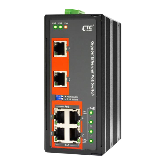
Page 8: Panels
Panels Figure 2. Top Panel Figure 1. Front Panel Description UTP RJ-45 ports (support PoE function) UTP RJ-45 ports DIP switch Power & Fault LED indicators PoE LED indicators Link/ACT LED indicators for UTP RJ-45 ports Speed LED indicators for UTP RJ-45 ports Terminal block Earth grounding connection... -
Page 9: Lan Ports
LAN Ports IGS-600-4PH(E)24 models have 6 LAN ports (labeled 1~6) on the front panel. The LAN ports that utilize shielded RJ-45 connectors support 10/100/1000M. PoE Ports 4 LAN ports (labeled 1~4) support PoE (Power over Ethernet) per IEEE802.3af (15.4W) or IEEE802.3at (30W) for connection to standard PoE PD (Power Devices) such as IP Cameras, Access Points, IP Phones, Digital Signage, etc. -
Page 10: Dip Switch
DIP Switch DIP No. Function Description Alarm Provide alarm relay and fault LED indication if Enable * there is a power failure in one supply. Disable alarm relay and fault LED indication if there is a power failure in one supply. Alarm Connecting to a single power source, place this Disable... -
Page 11: Recommended Power, Alarm, Ground Wiring Scheme
Recommended Power, Alarm, Ground Wiring Scheme DC Power Connection A removable terminal block on the top panel provides both power and alarm connections. Power can be provided through the dual inputs from separate sources (PWR1 & PWR2). One power supply is enough to power up the device. -
Page 12: Alarm Relay Connection
Alarm Relay Connection The alarm relay contact can be wired into an alarm circuit which senses an alarm condition when the contact is broken. The alarm relay is normally closed when there is no alarm condition. The alarm conditions are user programmable through management to include power, link faults or other fault conditions. -
Page 13: Led Indicators
LED Indicators Color Status Definition Power is connected and active at the PWR1/PWR2 input terminal PWR1 Green PWR2 connection. PWR1/PWR2 is not connected. One of the power inputs has fault condition (Alarm DIP switch must be enabled). Fault Amber Normal operation without power faults or Alarm DIP switch is disabled. -
Page 14: Installation
Installation The switch can be mounted on the wall or installed in DIN rail depending on your installation needs. When installing the wall-mounting bracket (optional accessory) and DIN rail bracket, be sure to correctly align the orientation pin. Figure 8. DIN Rail Figure 9. - Page 15 Version Date Description 2020/4/30 Use new document format Revise spec. Revise all top panel images...
Need help?
Do you have a question about the IGS-600-4PH24 and is the answer not in the manual?
Questions and answers