ZyXEL Communications ES-3124 User Manual
Es-3124 series intelligent layer 2+ switch
Hide thumbs
Also See for ES-3124:
- User manual (228 pages) ,
- Support notes (124 pages) ,
- Quick start manual (11 pages)

Related Manuals for ZyXEL Communications ES-3124


Summary of Contents for ZyXEL Communications ES-3124
- Page 1 ES-3124 Series Intelligent Layer 2+ Switch User’s Guide Version 3.70 Edition 2 4/2007...
-
Page 3: Copyright
Published by ZyXEL Communications Corporation. All rights reserved. Disclaimer ZyXEL does not assume any liability arising out of the application or use of any products, or software described herein. Neither does it convey any license under its patent rights nor the patent rights of others. -
Page 4: Certifications
ES-3124 Series User’s Guide Certifications Federal Communications Commission (FCC) Interference Statement This device complies with Part 15 of FCC rules. Operation is subject to the following two conditions: • This device may not cause harmful interference. • This device must accept any interference received, including interference that may cause undesired operations. - Page 5 PRODUIT CONFORME SELON 21 CFR 1040.10 ET 1040.11. Viewing Certifications 1 Go to http://www.zyxel.com. 2 Select your product from the drop-down list box on the ZyXEL home page to go to that product's page. 3 Select the certification you wish to view from this page.
-
Page 6: Safety Warnings
ES-3124 Series User’s Guide Safety Warnings For your safety, be sure to read and follow all warning notices and instructions. • Do NOT use this product near water, for example, in a wet basement or near a swimming pool. • Do NOT expose your device to dampness, dust or corrosive liquids. - Page 7 ES-3124 Series User’s Guide This product is recyclable. Dispose of it properly. Safety Warnings...
-
Page 8: Zyxel Limited Warranty
Any replacement will consist of a new or re-manufactured functionally equivalent product of equal or higher value, and will be solely at the discretion of ZyXEL. This warranty shall not apply if the product has been modified, misused, tampered with, damaged by an act of God, or subjected to abnormal working conditions. -
Page 9: Customer Support
ES-3124 Series User’s Guide Customer Support Please have the following information ready when you contact customer support. • Product model and serial number. • Warranty Information. • Date that you received your device. • Brief description of the problem and the steps you took to solve it. - Page 10 ES-3124 Series User’s Guide METHOD SUPPORT E-MAIL TELEPHONE WEB SITE REGULAR MAIL SALES E-MAIL FTP SITE LOCATION support@zyxel.no +47-22-80-61-80 www.zyxel.no ZyXEL Communications A/S Nils Hansens vei 13 NORWAY sales@zyxel.no +47-22-80-61-81 0667 Oslo Norway info@pl.zyxel.com +48 (22) 333 8250 www.pl.zyxel.com ZyXEL Communications ul.
-
Page 11: Table Of Contents
ES-3124 Series User’s Guide Table of Contents Copyright ........................3 Certifications ......................4 Safety Warnings ....................... 6 ZyXEL Limited Warranty..................8 Customer Support....................9 Table of Contents ....................11 List of Figures ......................23 List of Tables ......................27 Preface ........................31 Chapter 1 Getting to Know Your Switch ................ - Page 12 ES-3124 Series User’s Guide Chapter 3 Hardware Overview ....................47 3.1 Panel Connections ....................47 3.1.1 Console Port ....................49 3.1.2 Ethernet Ports ...................49 3.1.2.1 Default Ethernet Settings ..............50 3.1.3 Transceiver Slots ..................50 3.1.3.1 Transceiver Installation ..............50 3.1.3.2 Transceiver Removal ..............51 3.2 Rear Panel ......................52 3.2.1 Power Connector ..................52...
- Page 13 ES-3124 Series User’s Guide Chapter 7 Basic Setting ......................77 7.1 Overview ......................77 7.2 System Information ..................77 7.3 General Setup ....................80 7.4 Introduction to VLANs ..................82 7.5 Switch Setup Screen ..................83 7.6 IP Setup ......................85 7.6.1 Management IP Addresses ..............85 7.7 Port Setup...
- Page 14 ES-3124 Series User’s Guide 11.1.1 STP Terminology ..................115 11.1.2 How STP Works ...................116 11.1.3 STP Port States ...................116 11.1.4 Multiple RSTP ..................117 11.2 Spanning Tree Protocol Main Screen ............117 11.3 Configure Rapid Spanning Tree Protocol ............118 11.4 Rapid Spanning Tree Protocol Status ............121...
- Page 15 ES-3124 Series User’s Guide Chapter 17 Port Security......................151 17.1 About Port Security ..................151 17.2 Port Security Setup ..................151 Chapter 18 Classifier ....................... 155 18.1 About the Classifier and QoS .................155 18.2 Configuring the Classifier ................155 18.3 Viewing and Editing Classifier Configuration ..........158 18.4 Classifier Example ..................159...
- Page 16 ES-3124 Series User’s Guide 22.1.3 IGMP Snooping ...................177 22.2 Multicast Status .....................178 22.3 Multicast Setting ....................178 22.4 IGMP Filtering Profile ..................181 22.5 MVR Overview ....................183 22.5.1 Types of MVR Ports ................183 22.5.2 MVR Modes ..................183 22.5.3 How MVR Works ..................184 22.6 General MVR Configuration ................184...
- Page 17 ES-3124 Series User’s Guide Chapter 27 Access Control..................... 207 27.1 Access Control Overview ................207 27.2 The Access Control Main Screen ..............207 27.3 About SNMP ....................208 27.3.1 Supported MIBs ..................209 27.3.2 SNMP Traps ..................209 27.3.3 Configuring SNMP ................210 27.3.4 Setting Up Login Accounts ..............210...
- Page 18 ES-3124 Series User’s Guide Chapter 32 ARP Table......................237 32.1 ARP Table Overview ..................237 32.1.1 How ARP Works ...................237 32.2 Viewing the ARP Table ..................237 Chapter 33 Configure Clone ....................239 33.1 Configure Clone ....................239 Chapter 34 Introducing Commands ..................241 34.1 Overview ......................241...
- Page 19 ES-3124 Series User’s Guide 35.2.5 show mac address-table ..............277 35.3 ping .......................278 35.4 traceroute .......................278 35.5 Copy Port Attributes ..................279 35.6 Configuration File Maintenance ..............280 35.6.1 Using a Different Configuration File ............280 35.6.2 Resetting to the Factory Default ............281 Chapter 36 Configuration Mode Commands.................
- Page 20 ES-3124 Series User’s Guide 37.2.11 qos priority ..................302 37.2.12 name ....................303 37.2.13 speed-duplex ..................303 37.2.14 test ......................303 37.3 Interface no Command Examples ..............304 37.3.1 no bandwidth-limit .................304 Chapter 38 IEEE 802.1Q Tagged VLAN Commands ............. 305 38.1 Configuring Tagged VLAN ................305 38.2 Global VLAN1Q Tagged VLAN Configuration Commands ......306...
- Page 21 ES-3124 Series User’s Guide Appendix A Product Specifications ..................325 Appendix B IP Addresses and Subnetting ................329 Index........................337 Table of Contents...
- Page 22 ES-3124 Series User’s Guide Table of Contents...
-
Page 23: List Of Figures
Figure 29 Status (ES-3124PWR) ................70 Figure 30 Status (ES-3124-4F) ................70 Figure 31 Status: Port Details (ES-3124PWR) ............72 Figure 32 Status: Port Details (ES-3124-4F) ............73 Figure 33 System Info (ES-3124PWR) ..............78 Figure 34 System Info (ES-3124-4F) ..............79 Figure 35 General Setup .................. - Page 24 ES-3124 Series User’s Guide Figure 39 Port Setup (ES-3124 and ES-3124-4F) ..........90 Figure 40 Port Setup (ES-3124F) ................. 91 Figure 41 Port VLAN Trunking ................95 Figure 42 Switch Setup: Select VLAN Type ............96 Figure 43 VLAN: VLAN Status ................96 Figure 44 Static VLAN Details ................
- Page 25 ES-3124 Series User’s Guide Figure 82 MVR Network Example ................. 183 Figure 83 MVR Multicast Television Example ............184 Figure 84 MVR ...................... 185 Figure 85 MVR: Group Configuration ..............187 Figure 86 MVR Configuration Example ..............188 Figure 87 MVR Configuration Example ..............189 Figure 88 MVR Group Configuration Example .............
- Page 26 ES-3124 Series User’s Guide Figure 125 ARP Table ................... 238 Figure 126 Configure Clone .................. 239 Figure 127 no port-access-authenticator Command Example ......289 Figure 128 Pop-up Blocker ..................316 Figure 129 Internet Options .................. 317 Figure 130 Internet Options ................... 318 Figure 131 Pop-up Blocker Settings ..............
-
Page 27: List Of Tables
ES-3124 Series User’s Guide List of Tables Table 1 Model-specific Features ................33 Table 2 Panel Connections ................... 48 Table 3 LEDs ......................53 Table 4 Navigation Panel Sub-links Overview ............57 Table 5 Web Configurator Screen Sub-links Details ..........58 Table 6 Navigation Panel Links ................ - Page 28 Table 73 Syslog Severity Levels ................223 Table 74 Syslog ..................... 224 Table 75 Syslog: Server Setup ................225 Table 76 ZyXEL Clustering Management Specifications ........227 Table 77 Cluster Management: Status ..............229 Table 78 FTP Upload to Cluster Member Example ..........231 Table 79 Clustering Management Configuration ...........
- Page 29 ES-3124 Series User’s Guide Table 82 Configure Clone ..................240 Table 83 Command Interpreter Mode Summary ........... 244 Table 84 Command Summary: User Mode ............248 Table 85 Command Summary: Enable Mode ............249 Table 86 Command Summary: Configuration Mode ..........254 Table 87 interface port-channel Commands ............
- Page 30 ES-3124 Series User’s Guide List of Tables...
-
Page 31: Preface
Settings and then click Control Panel. • “e.g.,” is a shorthand for “for instance”, and “i.e.,” means “that is” or “in other words”. • The ES-3124 Series Intelligent Layer 2+ Switch may be referred to as “the switch” or “the device” in this User’s Guide. -
Page 32: User Guide Feedback
User Guide Feedback Help us help you. E-mail all User Guide-related comments, questions or suggestions for improvement to techwriters@zyxel.com.tw or send regular mail to The Technical Writing Team, ZyXEL Communications Corp., 6 Innovation Road II, Science-Based Industrial Park, Hsinchu, 300, Taiwan. Thank you. -
Page 33: Getting To Know Your Switch
This chapter introduces the main features and applications of the switch. 1.1 Introduction This User’s Guide covers the following switch models: ES-3124, ES-3124-4F, ES-3124-PWR and ES-3124F. The following table lists features that are specific to the individual models. The other features discussed in this chapter are common to all of the models covered in this User’s Guide. - Page 34 ES-3124 Series User’s Guide VLAN A VLAN (Virtual Local Area Network) allows a physical network to be partitioned into multiple logical networks. Devices on a logical network belong to one group. A device can belong to more than one group. With VLAN, a device cannot directly talk to or hear from devices that are not in the same group(s);...
- Page 35 ES-3124 Series User’s Guide Link Aggregation Link aggregation (trunking) is the grouping of physical ports into one logical higher-capacity link. You may want to trunk ports if for example, it is cheaper to use multiple lower-speed links than to under-utilize a high-speed, but more costly, single-port link.
-
Page 36: System Monitoring
ES-3124 Series User’s Guide • Configuration and Firmware Maintenance You can backup or restore the switch configuration or upgrade the firmware on the switch. IP Protocols • IP Host (No routing) • Telnet for configuration and monitoring • SNMP for management •... -
Page 37: Hardware Features
ES-3124 Series User’s Guide Quality of Service • Eight queues so you can ensure mission-critical data gets delivered on time. • Follows the IEEE 802.1p priority setting standard based on source/destination MAC addresses. 1.3 Hardware Features This section describes the hardware features of the switch. -
Page 38: Applications
ES-3124 Series User’s Guide Console Port Use the console port for local management of the switch. Backup Power Supply Port Connect a backup power supply device to this port to ensure uninterrupted network connection in the event of a power failure. -
Page 39: Bridging Example
ES-3124 Series User’s Guide Figure 1 Backbone Application 1.4.2 Bridging Example In this example application the switch connects different company departments (RD and Sales) to the corporate backbone. It can alleviate bandwidth contention and eliminate server and network bottlenecks. All users that need high bandwidth can connect to high-speed department servers via the switch. -
Page 40: Ieee 802.1Q Vlan Application Examples
ES-3124 Series User’s Guide Switching to higher-speed LANs such as ATM (Asynchronous Transmission Mode) is not feasible for most people due to the expense of replacing all existing Ethernet cables and adapter cards, restructuring your network and complex maintenance. The switch can provide the same bandwidth as ATM at much lower cost while still being able to use existing adapters and switches. -
Page 41: Vlan Shared Server Example
ES-3124 Series User’s Guide Figure 4 Tag-based VLAN Application 1.4.4.2 VLAN Shared Server Example Shared resources such as a server can be used by all ports in the same VLAN as the server, as shown in the following example. In this example, only ports that need access to the server need belong to VLAN 1. - Page 42 ES-3124 Series User’s Guide Chapter 1 Getting to Know Your Switch...
-
Page 43: Hardware Installation And Connection
ES-3124 Series User’s Guide H A P T E R Hardware Installation and Connection This chapter shows you how to install and connect the switch. 2.1 Freestanding Installation 1 Make sure the switch is clean and dry. 2 Set the switch on a smooth, level surface strong enough to support the weight of the switch and the connected cables. -
Page 44: Mounting The Switch On A Rack
ES-3124 Series User’s Guide 2.2 Mounting the Switch on a Rack This section lists the rack mounting requirements and precautions and describes the installation steps. 2.2.1 Rack-mounted Installation Requirements • Two mounting brackets. • Eight M3 flat head screws and a #2 Philips screwdriver. -
Page 45: Figure 8 Mounting The Switch On A Rack
ES-3124 Series User’s Guide Figure 8 Mounting the Switch on a Rack 2 Using a #2 Philips screwdriver, install the M5 flat head screws through the mounting bracket holes into the rack. 3 Repeat steps to attach the second mounting bracket on the other side of the rack. - Page 46 ES-3124 Series User’s Guide Chapter 2 Hardware Installation and Connection...
-
Page 47: Chapter 3 Hardware Overview
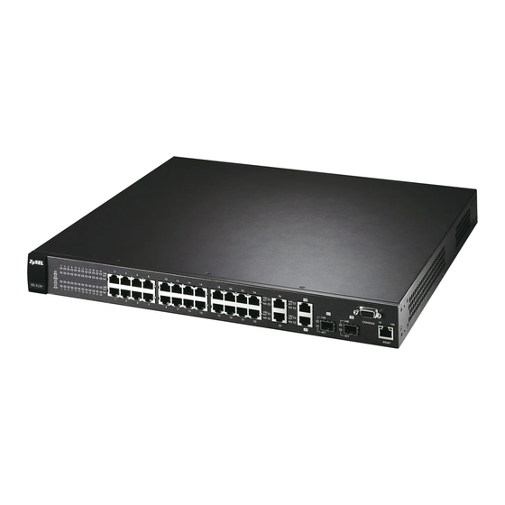
This chapter describes the front panel and rear panel of the switch and shows you how to make the hardware connections. 3.1 Panel Connections The figure below shows the front panel of the switch. Figure 9 Front Panel: ES-3124 RJ-45 Gigabit Ports for Stacking Console Port Management Port... -
Page 48: Figure 11 Front Panel: Es-3124Pwr
ES-3124 Series User’s Guide Figure 11 Front Panel: ES-3124PWR RJ-45 Gigabit Ports for Stacking Console Port Management Port 10/100 Mbps PoE Ethernet Ports LEDs RJ-45 Gigabit / Mini-GBIC Dual Personality Interfaces Figure 12 Front Panel: ES-3124F Mini-GBIC Ports for Stacking... -
Page 49: Console Port
100Mbps Fast Ethernet, the speed can be 10Mbps or 100Mbps and the duplex mode can be half duplex or full duplex. The ES-3124 and ES-3124PWR also come with two pairs of Gigabit Ethernet/mini-GBIC ports. The mini-GBIC ports have priority over the Gigabit ports. This means that if a mini- GBIC port and the corresponding Gigabit port are connected at the same time, the Gigabit port will be disabled. -
Page 50: Default Ethernet Settings
Gigabit ports. This means that if a mini-GBIC port and the corresponding Gigabit port are connected at the same time, the Gigabit port will be disabled. The ES-3124-4F and ES-3124F also have two mini-GBIC ports for connection to other switches. -
Page 51: Transceiver Removal
ES-3124 Series User’s Guide Figure 13 Transceiver Installation Example 2 Press the transceiver firmly until it clicks into place. 3 The switch automatically detects the installed transceiver. Check the LEDs to verify that it is functioning properly. Figure 14 Installed Transceiver 3.1.3.2 Transceiver Removal... -
Page 52: Rear Panel
ES-3124 Series User’s Guide 3.2 Rear Panel The following figure shows the rear panel of the switch. The rear panel contains the connector for external backup power supply (BPS), the power receptacle, and the power switch (DC models only). Figure 17 Rear Panel (AC models) Figure 18 Rear Panel (DC models) 3.2.1 Power Connector... -
Page 53: Leds
The system is on and functioning properly. The power is off or the system is not ready/malfunctioning. There is a hardware failure. The system is functioning normally. Ethernet ports (ES-3124 and ES-3124-4F only) LNK/ACT Green Blinking The system is transmitting/receiving to/from a 10 Mbps Ethernet network. - Page 54 ES-3124 Series User’s Guide Table 3 LEDs (continued) COLOR STATUS DESCRIPTION Gigabit Port LNK/ACT Green Blinking The system is transmitting/receiving to/from a 1000 Mbps Ethernet network. The link to a 1000 Mbps Ethernet network is up. Amber Blinking The system is transmitting/receiving to/from a 100 Mbps Ethernet network.
-
Page 55: The Web Configurator
ES-3124 Series User’s Guide H A P T E R The Web Configurator This section introduces the configuration and functions of the web configurator. This guide uses the ES-3124PWR screens as an example. The screens may vary slightly for different ES- 3124 models. -
Page 56: The Status Screen
ES-3124 Series User’s Guide Figure 19 Web Configurator: Login 4 Click OK to view the first web configurator screen. 4.3 The Status Screen The Status screen is the first screen that displays when you access the web configurator. The following figure shows the navigating components of a web configurator screen. -
Page 57: Menu Overview
ES-3124 Series User’s Guide B, C, D, E - These are quick links which allow you to perform certain tasks no matter which screen you are currently working in. B - Click this link to save your configuration into the switch’s nonvolatile memory. -
Page 58: Table 5 Web Configurator Screen Sub-Links Details
ES-3124 Series User’s Guide The following table lists the various web configurator screens within the sub-links. Table 5 Web Configurator Screen Sub-links Details ADVANCED BASIC SETTING ROUTING PROTOCOL MANAGEMENT APPLICATION System Info VLAN Static Routing Maintenance General Setup VLAN Status... -
Page 59: Table 6 Navigation Panel Links
ES-3124 Series User’s Guide The following table describes the links in the navigation panel. Table 6 Navigation Panel Links LINK DESCRIPTION Basic Settings System Info This link takes you to a screen that displays general system and hardware monitoring information. -
Page 60: Change Your Password
ES-3124 Series User’s Guide Table 6 Navigation Panel Links (continued) LINK DESCRIPTION Routing Protocol Static Routing This link takes you to screens where you can configure static routes. A static route defines how the switch should forward traffic by configuring the TCP/IP parameters manually. -
Page 61: Saving Your Configuration
ES-3124 Series User’s Guide Figure 21 Change Administrator Login Password 4.5 Saving Your Configuration When you are done modifying the settings in a screen, click Apply to save your changes back to the run-time memory. Settings in the run-time memory are lost when the switch’s power is turned off. -
Page 62: Resetting The Switch
ES-3124 Series User’s Guide 6 Forgetting the password and/or IP address. 7 Preventing all services from accessing the switch. 8 Changing a service port number but forgetting it. Note: Be careful not to lock yourself and others out of the switch. -
Page 63: Reset To The Factory Defaults
ES-3124 Series User’s Guide Figure 22 Example Xmodem Upload Type the configuration file's location, or click Browse to search for it. Choose the 1K Xmodem protocol. Then click Send. 7 After a configuration file upload, type to restart the switch. -
Page 64: Logging Out Of The Web Configurator
ES-3124 Series User’s Guide 4 Type after the " " message. atbr Enter Debug Mode Figure 24 Resetting the Switch: Via the Console Port Bootbase Version: V0.6 | 03/06/2006 09:21:13 RAM:Size = 32 Mbytes DRAM POST: Testing: 32768K OK DRAM Test SUCCESS ! FLASH: Intel 32M ZyNOS Version: 3.70(AID.0)b0 | 4/28/2006 17:27:36... -
Page 65: Initial Setup Example
ES-3124 Series User’s Guide H A P T E R Initial Setup Example This chapter shows how to set up the switch for an example network. 5.1 Overview The following lists the configuration steps for the initial setup: • Create a VLAN •... -
Page 66: Setting Port Vid
ES-3124 Series User’s Guide 1 Click Advanced Application and VLAN in the navigation panel and click the Static VLAN link. 2 In the Static VLAN screen, select ACTIVE, enter a descriptive name in the Name field and enter 2 in the VLAN Group ID field for the VLAN2 network. -
Page 67: Configuring Switch Management Ip Address
ES-3124 Series User’s Guide Figure 27 Initial Setup Network Example: Port VID 1 Click Advanced Applications and VLAN in the navigation panel. Then click the VLAN Port Setting link. 2 Enter 2 in the PVID field for port 1 and click Apply to save your changes back to the run-time memory. - Page 68 ES-3124 Series User’s Guide 3 Click Basic Setting and IP Setup in the navigation panel. 4 Configure the related fields in the IP Setup screen. For the VLAN2 network, enter 192.168.2.1 as the IP address and 255.255.255.0 as the subnet mask.
-
Page 69: System Status And Port Statistics
To view the port statistics, click Status in all web configurator screens to display the Status screen as shown next. Note: The ES-3124PWR screen is different from the other models covered in this UG. The screen from the ES-3124-4F model is shown for comparison. Chapter 6 System Status and Port Statistics... -
Page 70: Figure 29 Status (Es-3124Pwr)
ES-3124 Series User’s Guide Figure 29 Status (ES-3124PWR) Figure 30 Status (ES-3124-4F) Chapter 6 System Status and Port Statistics... -
Page 71: Status: Port Details
Use this screen to check status and detailed performance data about an individual port on the switch. Note: The ES-3124PWR screen is different from the other models covered in this UG.The screen from ES-3124-4F model is shown for comparison. Chapter 6 System Status and Port Statistics... -
Page 72: Figure 31 Status: Port Details (Es-3124Pwr)
ES-3124 Series User’s Guide Figure 31 Status: Port Details (ES-3124PWR) Chapter 6 System Status and Port Statistics... -
Page 73: Figure 32 Status: Port Details (Es-3124-4F)
ES-3124 Series User’s Guide Figure 32 Status: Port Details (ES-3124-4F) The following table describes the labels in this screen. Table 8 Status: Port Details LABEL DESCRIPTION Port Info Name This field shows the name of the port. Link This field shows whether the Ethernet connection is down, and the speed/duplex mode. - Page 74 ES-3124 Series User’s Guide Table 8 Status: Port Details (continued) LABEL DESCRIPTION This field shows the power consumption of the powered device connected to the port. PowerConsumption This field is not available for the Gigabit and mini-GBIC ports. (mW) (PWR models only) PD MaxCurrent This field shows the maximum current a powered device can get from the switch.
- Page 75 ES-3124 Series User’s Guide Table 8 Status: Port Details (continued) LABEL DESCRIPTION Excessive This is a count of frames for which transmission failed due to excessive collisions. Excessive collision is defined as the number of maximum collisions before the retransmission count is reset.
- Page 76 ES-3124 Series User’s Guide Chapter 6 System Status and Port Statistics...
-
Page 77: Chapter 7 Basic Setting
You can check the firmware version number and monitor the switch temperature, fan speeds and voltage in this screen. Note: The ES-3124PWR screen is different from the other models covered in this UG. The screen from the ES-3124-4F model is shown for comparison. Chapter 7 Basic Setting... -
Page 78: Figure 33 System Info (Es-3124Pwr)
ES-3124 Series User’s Guide Figure 33 System Info (ES-3124PWR) Chapter 7 Basic Setting... -
Page 79: Figure 34 System Info (Es-3124-4F)
ES-3124 Series User’s Guide Figure 34 System Info (ES-3124-4F) The following table describes the labels in this screen. Table 9 System Info LABEL DESCRIPTION System Name This field displays the descriptive name of the switch for identification purposes. ZyNOS F/W... -
Page 80: General Setup
ES-3124 Series User’s Guide Table 9 System Info (continued) LABEL DESCRIPTION This field displays the maximum temperature measured at this sensor. This field displays the minimum temperature measured at this sensor. Threshold This field displays the upper temperature limit at this sensor. -
Page 81: Figure 35 General Setup
ES-3124 Series User’s Guide Figure 35 General Setup The following table describes the labels in this screen. Table 10 General Setup LABEL DESCRIPTION System Name Choose a descriptive name for identification purposes. This name consists of up to 64 printable characters; spaces are allowed. -
Page 82: Introduction To Vlans
ES-3124 Series User’s Guide Table 10 General Setup (continued) LABEL DESCRIPTION Use Time Server Enter the time service protocol that your timeserver uses. Not all time servers when Bootup support all protocols, so you may have to use trial and error to find a protocol that works. -
Page 83: Switch Setup Screen
ES-3124 Series User’s Guide Note: VLAN is unidirectional; it only governs outgoing traffic. Chapter 8 on page 93 for information on port-based and 802.1Q tagged VLANs. 7.5 Switch Setup Screen Click Basic Setting and then Switch Setup in the navigation panel to display the screen as shown. - Page 84 ES-3124 Series User’s Guide Table 11 Switch Setup (continued) LABEL DESCRIPTION Aging Time Enter a time from 10 to 3000 seconds. This is how long all dynamically learned MAC addresses remain in the MAC address table before they age out (and must be relearned).
-
Page 85: Ip Setup
ES-3124 Series User’s Guide 7.6 IP Setup Use the IP Setup screen to configure the default gateway device, the default domain name server and add switch IP address. 7.6.1 Management IP Addresses The switch needs an IP address for it to be managed over the network. The factory default IP address is 192.168.1.1. -
Page 86: Figure 37 Ip Setup
ES-3124 Series User’s Guide Figure 37 IP Setup Chapter 7 Basic Setting... -
Page 87: Table 12 Ip Setup
ES-3124 Series User’s Guide The following table describes the labels in this screen. Table 12 IP Setup LABEL DESCRIPTION Domain DNS (Domain Name System) is for mapping a domain name to its corresponding IP Name Server address and vice versa. Enter a domain name server IP address in order to be able to use a domain name instead of an IP address. -
Page 88: Port Setup
Auto-negotiation regulates the speed and duplex of each port, based on the capability of both devices. When auto-negotiation is turned on, an Ethernet port on the ZyXEL switch negotiates with the peer automatically to determine the connection speed and duplex mode. If the peer... -
Page 89: Figure 38 Port Setup (Es-3124Pwr)
ES-3124 Series User’s Guide Figure 38 Port Setup (ES-3124PWR) Chapter 7 Basic Setting... -
Page 90: Figure 39 Port Setup (Es-3124 And Es-3124-4F)
ES-3124 Series User’s Guide Figure 39 Port Setup (ES-3124 and ES-3124-4F) Chapter 7 Basic Setting... -
Page 91: Figure 40 Port Setup (Es-3124F)
ES-3124 Series User’s Guide Figure 40 Port Setup (ES-3124F) The following table describes the labels in this screen. Table 13 Port Setup LABEL DESCRIPTION Settings in this row apply to all ports. Use this row only if you want to make some settings the same for all ports. Use this row first to set the common settings and then make adjustments on a port-by-port basis. - Page 92 ES-3124 Series User’s Guide Table 13 Port Setup (continued) LABEL DESCRIPTION Name Enter a descriptive name that identifies this port. Type This field displays 10/100M for an Ethernet/Fast Ethernet connection, 100M for an Fast Ethernet connection and 10/100/1000M for Gigabit connections.
-
Page 93: Chapter 8 Vlan
ES-3124 Series User’s Guide H A P T E R VLAN The type of screen you see here depends on the VLAN Type you selected in the Switch Setup screen. This chapter shows you how to configure 802.1Q tagged and port-based VLANs. -
Page 94: Automatic Vlan Registration
ES-3124 Series User’s Guide 8.2 Automatic VLAN Registration GARP and GVRP are the protocols used to automatically register VLAN membership across switches. 8.2.1 GARP GARP (Generic Attribute Registration Protocol) allows network switches to register and de- register attribute values with other GARP participants within a bridged LAN. GARP is a protocol that provides a generic mechanism for protocols that serve a more specific application, for example, GVRP. -
Page 95: Port Vlan Trunking
ES-3124 Series User’s Guide Table 14 IEEE 802.1Q VLAN Terminology (continued) VLAN PARAMETER TERM DESCRIPTION VLAN Port Port VID This is the VLAN ID assigned to untagged frames that this port received. Acceptable Frame You may choose to accept both tagged and untagged... -
Page 96: Static Vlan
ES-3124 Series User’s Guide Figure 42 Switch Setup: Select VLAN Type 8.5 Static VLAN Use a static VLAN to decide whether an incoming frame on a port should be • sent to a VLAN group as normal depends on its VLAN tag. -
Page 97: Static Vlan Details
ES-3124 Series User’s Guide Table 15 VLAN: VLAN Status (continued) LABEL DESCRIPTION This is the VLAN identification number that was configured in the Static VLAN screen. Elapsed Time This field shows how long it has been since a normal VLAN was registered or a static VLAN was set up. -
Page 98: Configure A Static Vlan
ES-3124 Series User’s Guide 8.5.3 Configure a Static VLAN Use this screen to configure and view 802.1Q VLAN parameters for the switch. See Section 8.5 on page 96 for more information on static VLAN. To configure a static VLAN, click Static VLAN in the VLAN Status screen to display the screen as shown next. -
Page 99: Figure 45 Vlan: Static Vlan
ES-3124 Series User’s Guide Figure 45 VLAN: Static VLAN Chapter 8 VLAN... -
Page 100: Configure Vlan Port Settings
ES-3124 Series User’s Guide The following table describes the related labels in this screen. Table 17 VLAN: Static VLAN LABEL DESCRIPTION ACTIVE Select this check box to activate the VLAN settings. Name Enter a descriptive name for the VLAN group for identification purposes. -
Page 101: Figure 46 Vlan: Vlan Port Setting
ES-3124 Series User’s Guide Figure 46 VLAN: VLAN Port Setting Chapter 8 VLAN... -
Page 102: Table 18 Vlan: Vlan Port Setting
ES-3124 Series User’s Guide The following table describes the labels in this screen. Table 18 VLAN: VLAN Port Setting LABEL DESCRIPTION GVRP GVRP (GARP VLAN Registration Protocol) is a registration protocol that defines a way for switches to register necessary VLAN members on ports across the network. -
Page 103: Protocol Based Vlans
ES-3124 Series User’s Guide 8.6 Protocol Based VLANs Protocol based VLANs allow you to group traffic into logical VLANs based on the protocol you specify. When an upstream frame is received on a port (configured for a protocol based VLAN), the switch checks if a tag is added already and its protocol. The untagged packets of the same protocol are then placed in the same protocol based VLAN. -
Page 104: Figure 48 Protocol Based Vlan
ES-3124 Series User’s Guide Figure 48 Protocol Based VLAN The following table describes the labels in this screen. Table 19 Protocol Based VLAN Setup LABEL DESCRIPTION Active Check this box to activate this protocol based VLAN. Port Type a port to be included in this protocol based VLAN. -
Page 105: Create An Ip-Based Vlan Example
ES-3124 Series User’s Guide Table 19 Protocol Based VLAN Setup (continued) LABEL DESCRIPTION Priority This field shows the priority which is assigned to frames belonging to this protocol based VLAN. Delete Click this to delete the protocol based VLANs which you marked for deletion. -
Page 106: Port-Based Vlan Setup
ES-3124 Series User’s Guide 8.9 Port-based VLAN Setup Port-based VLANs are VLANs where the packet forwarding decision is based on the destination MAC address and its associated port. Port-based VLANs require allowed outgoing ports to be defined for each port. Therefore, if... -
Page 107: Figure 50 Port Based Vlan Setup (All Connected)
ES-3124 Series User’s Guide Figure 50 Port Based VLAN Setup (All Connected) Chapter 8 VLAN... -
Page 108: Figure 51 Port Based Vlan Setup (Port Isolation)
ES-3124 Series User’s Guide Figure 51 Port Based VLAN Setup (Port Isolation) Chapter 8 VLAN... -
Page 109: Table 20 Port Based Vlan Setup
ES-3124 Series User’s Guide The following table describes the labels in this screen. Table 20 Port Based VLAN Setup LABEL DESCRIPTION Setting Wizard Choose All connected or Port isolation. All connected means all ports can communicate with each other, that is, there are no virtual LANs. - Page 110 ES-3124 Series User’s Guide Chapter 8 VLAN...
-
Page 111: Static Mac Forwarding
ES-3124 Series User’s Guide H A P T E R Static MAC Forwarding Use these screens to configure static MAC address forwarding. 9.1 Configuring Static MAC Forwarding A static MAC address is an address that has been manually entered in the MAC address table. -
Page 112: Table 21 Static Mac Forwarding
ES-3124 Series User’s Guide The following table describes the labels in this screen. Table 21 Static MAC Forwarding LABEL DESCRIPTION Active Select this check box to activate your rule. You may temporarily deactivate a rule without deleting it by clearing this check box. -
Page 113: Chapter 10 Filtering
ES-3124 Series User’s Guide H A P T E R Filtering This chapter discusses static IP and MAC address port filtering. 10.1 Configure a Filtering Rule Filtering means sifting traffic going through the switch based on the source and/or destination MAC addresses and VLAN group (ID). - Page 114 ES-3124 Series User’s Guide Table 22 FIltering (continued) LABEL DESCRIPTION Action Select Discard source to drop frame from the source MAC address (specified in the MAC field). The switch can still send frames to the MAC address. Select Discard destination to drop frames to the destination MAC address (specified in the MAC address).
-
Page 115: Spanning Tree Protocol
ES-3124 Series User’s Guide H A P T E R Spanning Tree Protocol The switch supports Spanning Tree Protocol (STP) and Rapid Spanning Tree Protocol (RSTP) as defined in the following standards. • IEEE 802.1D Spanning Tree Protocol • IEEE 802.1w Rapid Spanning Tree Protocol The switch also allows you to set up multiple STP configurations (or trees). -
Page 116: How Stp Works
ES-3124 Series User’s Guide Table 23 STP Path Costs RECOMMENDED LINK SPEED RECOMMENDED VALUE ALLOWED RANGE RANGE Path Cost 16Mbps 40 to 400 1 to 65535 Path Cost 100Mbps 10 to 60 1 to 65535 Path Cost 1Gbps 3 to 10... -
Page 117: Multiple Rstp
11.1.4 Multiple RSTP MRSTP (Multiple RSTP) is ZyXEL’s proprietary feature that is compatible with RSTP and STP. With MRSTP, you can have more than one spanning tree on your switch and assign port(s) to each tree. Each spanning tree operates independently with its own bridge information. -
Page 118: Configure Rapid Spanning Tree Protocol
ES-3124 Series User’s Guide Figure 55 Spanning Tree Protocol RSTP and MRSTP The following table describes the labels in this screen. Table 25 Spanning Tree Protocol: Status LABEL DESCRIPTION RSTP This link takes you to the Rapid Spanning Tree Protocol configuration screen. See Section 11.3 on page... -
Page 119: Figure 56 Rstp: Configuration
ES-3124 Series User’s Guide Figure 56 RSTP: Configuration Chapter 11 Spanning Tree Protocol... -
Page 120: Table 26 Rstp: Configuration
ES-3124 Series User’s Guide The following table describes the labels in this screen. Table 26 RSTP: Configuration LABEL DESCRIPTION Status Click Status to display the RSTP Status screen (see Figure 57 on page 121). Active Select this check box to activate RSTP. Clear this checkbox to disable RSTP. -
Page 121: Rapid Spanning Tree Protocol Status
ES-3124 Series User’s Guide Table 26 RSTP: Configuration (continued) LABEL DESCRIPTION Apply Click Apply to save your changes to the switch’s run-time memory. The switch loses these changes if it is turned off or loses power, so use the Save link on the top navigation panel to save your changes to the non-volatile memory when you are done configuring. -
Page 122: Configure Multiple Rapid Spanning Tree Protocol
ES-3124 Series User’s Guide Table 27 Rapid Spanning Tree Protocol: Status (continued) LABEL DESCRIPTION Max Age (second) This is the maximum time (in seconds) a switch can wait without receiving a configuration message before attempting to reconfigure. Forwarding Delay This is the time (in seconds) the root switch will wait before changing states (that (second) is, listening to learning to forwarding). -
Page 123: Figure 58 Mrstp: Configuration
ES-3124 Series User’s Guide Figure 58 MRSTP: Configuration Chapter 11 Spanning Tree Protocol... -
Page 124: Table 28 Mrstp: Configuration
ES-3124 Series User’s Guide The following table describes the labels in this screen. Table 28 MRSTP: Configuration LABEL DESCRIPTION Status Click Status to display the MRSTP Status screen (see Figure 57 on page 121). Tree This is a read only index number of the STP trees. -
Page 125: Multiple Rapid Spanning Tree Protocol Status
ES-3124 Series User’s Guide Table 28 MRSTP: Configuration (continued) LABEL DESCRIPTION Apply Click Apply to save your changes to the switch’s run-time memory. The switch loses these changes if it is turned off or loses power, so use the Save link on the top navigation panel to save your changes to the non-volatile memory when you are done configuring. - Page 126 ES-3124 Series User’s Guide Table 29 Spanning Tree Protocol: Status (continued) LABEL DESCRIPTION Max Age (second) This is the maximum time (in seconds) a switch can wait without receiving a configuration message before attempting to reconfigure. Forwarding Delay This is the time (in seconds) the root switch will wait before changing states (that (second) is, listening to learning to forwarding).
-
Page 127: Chapter 12 Bandwidth Control
ES-3124 Series User’s Guide H A P T E R Bandwidth Control This chapter shows you how you can cap the maximum bandwidth using the Bandwidth Control screen. 12.1 Bandwidth Control Overview Bandwidth control means defining a maximum allowable bandwidth for incoming and/or out- going traffic flows on a port. -
Page 128: Figure 60 Bandwidth Control
ES-3124 Series User’s Guide Figure 60 Bandwidth Control The following table describes the related labels in this screen. Table 30 Bandwidth Control LABEL DESCRIPTION Active Select this check box to enable bandwidth control on the switch. Port This field displays the port number. - Page 129 ES-3124 Series User’s Guide Table 30 Bandwidth Control (continued) LABEL DESCRIPTION Settings in this row apply to all ports. Use this row only if you want to make some settings the same for all ports. Use this row first to set the common settings and then make adjustments on a port-by-port basis.
- Page 130 ES-3124 Series User’s Guide Chapter 12 Bandwidth Control...
-
Page 131: Broadcast Storm Control
ES-3124 Series User’s Guide H A P T E R Broadcast Storm Control This chapter introduces and shows you how to configure the broadcast storm control feature. 13.1 Broadcast Storm Control Setup Broadcast storm control limits the number of broadcast, multicast and destination lookup failure (DLF) packets the switch receives per second on the ports. -
Page 132: Figure 61 Broadcast Storm Control
ES-3124 Series User’s Guide Figure 61 Broadcast Storm Control Chapter 13 Broadcast Storm Control... - Page 133 ES-3124 Series User’s Guide The following table describes the labels in this screen. Table 31 Broadcast Storm Control LABEL DESCRIPTION Active Select this check box to enable traffic storm control on the switch. Clear this check box to disable this feature.
- Page 134 ES-3124 Series User’s Guide Chapter 13 Broadcast Storm Control...
-
Page 135: Chapter 14 Mirroring
ES-3124 Series User’s Guide H A P T E R Mirroring This chapter discusses the Mirror setup screens. 14.1 Port Mirroring Setup Port mirroring allows you to copy a traffic flow to a monitor port (the port you copy the traffic to) in order that you can examine the traffic from the monitor port without interference. -
Page 136: Figure 62 Mirroring
ES-3124 Series User’s Guide Figure 62 Mirroring Chapter 14 Mirroring... -
Page 137: Table 32 Mirroring
ES-3124 Series User’s Guide The following table describes the labels in this screen. Table 32 Mirroring LABEL DESCRIPTION Active Select this check box to activate port mirroring on the switch. Clear this check box to disable the feature. Monitor The monitor port is the port you copy the traffic to in order to examine it in more detail Port without interfering with the traffic flow on the original port(s). - Page 138 ES-3124 Series User’s Guide Chapter 14 Mirroring...
-
Page 139: Chapter 15 Link Aggregation
ES-3124 Series User’s Guide H A P T E R Link Aggregation This chapter shows you how to logically aggregate physical links to form one logical, higher- bandwidth link. 15.1 Link Aggregation Overview Link aggregation (trunking) is the grouping of physical ports into one logical higher-capacity link. -
Page 140: Link Aggregation Id
ES-3124 Series User’s Guide 15.2.1 Link Aggregation ID LACP aggregation ID consists of the following information Table 33 Link Aggregation ID: Local Switch SYSTEM PRIORITY MAC ADDRESS PORT PRIORITY PORT NUMBER 0000 00-00-00-00-00 0000 0000 Table 34 Link Aggregation ID: Peer Switch... -
Page 141: Link Aggregation Setup
ES-3124 Series User’s Guide The following table describes the labels in this screen. Table 35 Link Aggregation Control Protocol Status LABEL DESCRIPTION Index This field displays the trunk ID to identify a trunk group, that is, one logical link containing multiple ports. -
Page 142: Figure 64 Link Aggregation: Configuration
ES-3124 Series User’s Guide Figure 64 Link Aggregation: Configuration Chapter 15 Link Aggregation... -
Page 143: Table 36 Link Aggregation Control Protocol: Configuration
ES-3124 Series User’s Guide The following table describes the labels in this screen. Table 36 Link Aggregation Control Protocol: Configuration LABEL DESCRIPTION Link Aggregation Control Protocol Active Select this checkbox to enable Link Aggregation Control Protocol (LACP). System LACP system priority is a number between 1 and 65,535. The switch with the lowest... - Page 144 ES-3124 Series User’s Guide Chapter 15 Link Aggregation...
-
Page 145: Chapter 16 Port Authentication
ES-3124 Series User’s Guide H A P T E R Port Authentication This chapter describes the 802.1x authentication method and RADIUS server connection setup. See Section 36.9 on page 293 for information on how to use the commands to configure additional Radius server settings as well as multiple Radius server configuration. -
Page 146: Tunnel Protocol Attribute
ES-3124 Series User’s Guide Note: Refer to the documentation that comes with your RADIUS server on how to configure a VSA. The following table describes the VSAs supported on the switch. Table 37 Supported VSA FUNCTION ATTRIBUTE Ingress Bandwidth Vendor-Id = 890... -
Page 147: Configuring Radius Server Settings
ES-3124 Series User’s Guide Click Advanced Application, Port Authentication in the navigation panel to display the screen as shown. Figure 66 Port Authentication 16.2.1 Configuring RADIUS Server Settings Use this screen to configure your RADIUS server settings. See Section 16.1.1 on page 145 more information on RADIUS servers. -
Page 148: Activate Ieee 802.1X Security
ES-3124 Series User’s Guide 16.2.2 Activate IEEE 802.1x Security Use this screen to activate IEEE 802.1x security. From the Port Authentication screen, display the configuration screen as shown. Figure 68 Port Authentication: 802.1x Chapter 16 Port Authentication... -
Page 149: Table 40 Port Authentication: 802.1X
ES-3124 Series User’s Guide The following table describes the labels in this screen. Table 40 Port Authentication: 802.1x LABEL DESCRIPTION Active Select this check box to permit 802.1x authentication on the switch. Note: You must first enable 802.1x authentication on the switch before configuring it on each port. - Page 150 ES-3124 Series User’s Guide Chapter 16 Port Authentication...
-
Page 151: Chapter 17 Port Security
ES-3124 Series User’s Guide H A P T E R Port Security This chapter shows you how to set up port security. 17.1 About Port Security Port security allows only packets with dynamically learned MAC addresses and/or configured static MAC addresses to pass through a port on the switch. The switch can learn up to 16K MAC addresses in total with no limit on individual ports other than the sum cannot exceed 16K. -
Page 152: Figure 69 Port Security
ES-3124 Series User’s Guide Figure 69 Port Security The following table describes the labels in this screen. Table 41 Port Security LABEL DESCRIPTION Active Select this option to enable port security on the switch. Port This field displays a port number. - Page 153 ES-3124 Series User’s Guide Table 41 Port Security (continued) LABEL DESCRIPTION Settings in this row apply to all ports. Use this row only if you want to make some settings the same for all ports. Use this row first to set the common settings and then make adjustments on a port-by-port basis.
- Page 154 ES-3124 Series User’s Guide Chapter 17 Port Security...
-
Page 155: Chapter 18 Classifier
ES-3124 Series User’s Guide H A P T E R Classifier This chapter introduces and shows you how to configure the packet classifier on the switch. 18.1 About the Classifier and QoS Quality of Service (QoS) refers to both a network's ability to deliver data with minimum delay, and the networking methods used to control the use of bandwidth. -
Page 156: Figure 70 Classifier
ES-3124 Series User’s Guide Figure 70 Classifier The following table describes the labels in this screen. Table 42 Classifier LABEL DESCRIPTION Active Select this option to enable this rule. Name Enter a descriptive name for this rule for identifying purposes. - Page 157 ES-3124 Series User’s Guide Table 42 Classifier (continued) LABEL DESCRIPTION Layer 2 Specify the fields below to configure a layer 2 classifier. VLAN Select Any to classify traffic from any VLAN or select the second option and specify the source VLAN ID in the field provided.
-
Page 158: Viewing And Editing Classifier Configuration
ES-3124 Series User’s Guide Table 42 Classifier (continued) LABEL DESCRIPTION Click Add to insert the entry in the summary table below. Cancel Click Cancel to reset the fields back to your previous configuration. Clear Click Clear to set the above fields back to the factory defaults. -
Page 159: Classifier Example
ES-3124 Series User’s Guide Table 44 Common Ethernet Types and Protocol Number ETHERNET TYPE PROTOCOL NUMBER ECMA Internet 0803 Chaosnet 0804 X.25 Level 3 0805 XNS Compat 0807 Banyan Systems 0BAD BBN Simnet 5208 IBM SNA 80D5 AppleTalk AARP 80F3... -
Page 160: Figure 72 Classifier: Example
ES-3124 Series User’s Guide Figure 72 Classifier: Example Chapter 18 Classifier... -
Page 161: Chapter 19 Policy Rule
ES-3124 Series User’s Guide H A P T E R Policy Rule This chapter shows you how to configure policy rules. 19.1 Policy Rules Overview A classifier distinguishes traffic into flows based on the configured criteria (refer to Chapter 18 on page 155 for more information). -
Page 162: Configuring Policy Rules
ES-3124 Series User’s Guide 19.2 Configuring Policy Rules You must first configure a classifier in the Classifier screen. Refer to Section 18.2 on page for more information. Click Advanced Applications and then Policy Rule in the navigation panel to display the screen as shown. -
Page 163: Table 46 Policy
ES-3124 Series User’s Guide The following table describes the labels in this screen. Table 46 Policy LABEL DESCRIPTION Active Select this option to enable the policy. Name Enter a descriptive name for identification purposes. Classifier(s) This field displays the active classifier(s) you configure in the Classifier screen. -
Page 164: Viewing And Editing Policy Configuration
ES-3124 Series User’s Guide Table 46 Policy (continued) LABEL DESCRIPTION Diffserv Select No change to keep the TOS and/or DSCP fields in the packets. Select Set the packet’s TOS field to set the TOS field with the value you configure in the TOS field. -
Page 165: Policy Example
ES-3124 Series User’s Guide The following table describes the labels in this screen. Table 47 Policy: Summary Table LABEL DESCRIPTION Index This field displays the policy index number. Click an index number to edit the policy. Active This field displays Yes when policy is activated and No when is it deactivated. -
Page 166: Figure 75 Policy Example
ES-3124 Series User’s Guide Figure 75 Policy Example Chapter 19 Policy Rule... -
Page 167: Chapter 20 Queuing Method
ES-3124 Series User’s Guide H A P T E R Queuing Method This chapter introduces the queuing methods supported. 20.1 Queuing Method Overview Queuing is used to help solve performance degradation when there is network congestion. Use the Queuing Method screen to configure queuing algorithms for outgoing traffic. See also Priority Queue Assignment in Switch Setup and 802.1p Priority in Port Setup for related... -
Page 168: Weighted Round Robin Scheduling (Wrr)
ES-3124 Series User’s Guide 20.1.3 Weighted Round Robin Scheduling (WRR) Round Robin Scheduling services queues on a rotating basis and is activated only when a port has more traffic than it can handle. A queue is a given an amount of bandwidth irrespective of the incoming traffic on that port. -
Page 169: Figure 76 Queuing Method
ES-3124 Series User’s Guide Figure 76 Queuing Method Chapter 20 Queuing Method... -
Page 170: Table 48 Queuing Method
ES-3124 Series User’s Guide The following table describes the labels in this screen. Table 48 Queuing Method LABEL DESCRIPTION Method Select SPQ (Strictly Priority Queuing), WFQ (Weighted Fair Scheduling) or WRR (Weighted Round Robin). Strictly Priority services queues based on priority only. When the highest priority queue empties, traffic on the next highest-priority queue begins. -
Page 171: Chapter 21 Vlan Stacking
ES-3124 Series User’s Guide H A P T E R VLAN Stacking This chapter shows you how to configure VLAN stacking on your switch. See the chapter on VLANs for more background information on Virtual LAN 21.1 VLAN Stacking Overview A service provider can use VLAN stacking to allow it to distinguish multiple customers’... -
Page 172: Vlan Stacking Port Roles
ES-3124 Series User’s Guide Figure 77 VLAN Stacking Example 21.2 VLAN Stacking Port Roles Each port can have three VLAN stacking “roles”, Normal, Access Port and Tunnel (the latter is for Gigabit ports only). • Select Normal for “regular” (non-VLAN stacking) IEEE 802.1Q frame switching. -
Page 173: Frame Format
ES-3124 Series User’s Guide Type is a standard Ethernet type code identifying the frame and indicates that whether the frame carries IEEE 802.1Q tag information. SP TPID (Service Provider Tag Protocol Identifier) is the service provider VLAN stacking tag type. Many vendors use 0x8100 or 0x9100. -
Page 174: Configuring Vlan Stacking
ES-3124 Series User’s Guide 21.4 Configuring VLAN Stacking Click Advanced Applications and then VLAN Stacking to display the screen as shown. Figure 78 VLAN Stacking Chapter 21 VLAN Stacking... - Page 175 ES-3124 Series User’s Guide The following table describes the labels in this screen. Table 52 VLAN Stacking LABEL DESCRIPTION Active Select this checkbox to enable VLAN stacking on the switch. SP TPID SP TPID is a standard Ethernet type code identifying the frame and indicates whether the frame carries IEEE 802.1Q tag information.
-
Page 176: Table 52 Vlan Stacking
ES-3124 Series User’s Guide Chapter 21 VLAN Stacking... -
Page 177: Chapter 22 Multicast
ES-3124 Series User’s Guide H A P T E R Multicast This chapter shows you how to configure various multicast features. 22.1 Multicast Overview Traditionally, IP packets are transmitted in one of either two ways - Unicast (1 sender to 1 recipient) or Broadcast (1 sender to everybody on the network). -
Page 178: Multicast Status
ES-3124 Series User’s Guide The switch forwards multicast traffic destined for multicast groups (that it has learned from IGMP snooping or that you have manually configured) to ports that are members of that group. IGMP snooping generates no additional network traffic, allowing you to significantly reduce multicast traffic passing through your switch. -
Page 179: Figure 80 Multicast Setting
ES-3124 Series User’s Guide Figure 80 Multicast Setting Chapter 22 Multicast... -
Page 180: Table 54 Multicast Setting
ES-3124 Series User’s Guide The following table describes the labels in this screen. Table 54 Multicast Setting LABEL DESCRIPTION IGMP Snooping Use this settings to configure IGMP Snooping. Active Select Active to enable IGMP Snooping to forward group multicast traffic only to ports that are members of that group. -
Page 181: Igmp Filtering Profile
ES-3124 Series User’s Guide Table 54 Multicast Setting (continued) LABEL DESCRIPTION IGMP Querier The switch treats an IGMP query port as being connected to an IGMP multicast Mode router (or server). The switch forwards IGMP join or leave packets to an IGMP query port. -
Page 182: Figure 81 Multicast: Igmp Filtering Profile
ES-3124 Series User’s Guide Figure 81 Multicast: IGMP Filtering Profile The following table describes the labels in this screen. Table 55 Multicast: IGMP Filtering Profile LABEL DESCRIPTION Profile Name Enter a descriptive name for the profile for identification purposes. To configure additional rule(s) for a profile that you have already added, enter the profile name and specify a different IP multicast address range. -
Page 183: Mvr Overview
ES-3124 Series User’s Guide 22.5 MVR Overview Multicast VLAN Registration (MVR) is designed for applications (such as Media-on-Demand (MoD)) that use multicast traffic across an Ethernet ring-based service provider network. MVR allows one single multicast VLAN to be shared among different subscriber VLANs on the network. -
Page 184: How Mvr Works
ES-3124 Series User’s Guide 22.5.3 How MVR Works The following figure shows a multicast television example where a subscriber device (such as a computer) in VLAN 1 receives multicast traffic from the streaming media server, S, via the switch. Multiple subscriber devices can connect through a port configured as the receiver on the switch. -
Page 185: Figure 84 Mvr
ES-3124 Series User’s Guide Figure 84 MVR Chapter 22 Multicast... -
Page 186: Table 56 Mvr
ES-3124 Series User’s Guide The following table describes the related labels in this screen. Table 56 MVR LABEL DESCRIPTION Active Select this check box to enable MVR to allow one single multicast VLAN to be shared among different subscriber VLANs on the network. -
Page 187: Mvr Group Configuration
ES-3124 Series User’s Guide 22.7 MVR Group Configuration All source ports and receiver ports belonging to a multicast group can receive multicast data sent to this multicast group. Configure MVR IP multicast group address(es) in the Group Configuration screen. Click Group Configuration in the MVR screen. -
Page 188: Mvr Configuration Example
ES-3124 Series User’s Guide Table 57 MVR: Group Configuration LABEL DESCRIPTION MVLAN This field displays the multicast VLAN ID. Name This field displays the descriptive name for this setting. Start Address This field displays the starting IP address of the multicast group. -
Page 189: Figure 87 Mvr Configuration Example
ES-3124 Series User’s Guide Figure 87 MVR Configuration Example To set the switch to forward the multicast group traffic to the subscribers, configure multicast group settings in the Group Configuration screen. The following figure shows an example where two multicast groups (News and Movie) are configured for the multicast VLAN 200. -
Page 190: Figure 88 Mvr Group Configuration Example
ES-3124 Series User’s Guide Figure 88 MVR Group Configuration Example Figure 89 MVR Group Configuration Example Chapter 22 Multicast... -
Page 191: Chapter 23 Dhcp Relay
ES-3124 Series User’s Guide H A P T E R DHCP Relay This chapter shows you how to set up DHCP relay. 23.1 DHCP Relay Overview DHCP (Dynamic Host Configuration Protocol, RFC 2131 and RFC 2132) allows individual clients to obtain TCP/IP configuration at start-up from a DHCP server. You can configure the switch to relay client DHCP requests to a DHCP server and the server's responses back to the clients. -
Page 192: Figure 90 Dhcp Relay
ES-3124 Series User’s Guide Figure 90 DHCP Relay The following table describes the labels in this screen. Table 58 DHCP Relay LABEL DESCRIPTION Active Select this check box to enable DHCP relay. Remote DHCP Enter the IP address of a DHCP server in dotted decimal notation. -
Page 193: Chapter 24 Static Route
ES-3124 Series User’s Guide H A P T E R Static Route This chapter shows you how to configure static routes. 24.1 Configuring Static Route Static routes tell the switch how to forward IP traffic when you configure the TCP/IP parameters manually. - Page 194 ES-3124 Series User’s Guide Table 59 Static Routing (continued) LABEL DESCRIPTION Destination IP This parameter specifies the IP network address of the final destination. Routing is Address always based on network number. If you need to specify a route to a single host, use a subnet mask of 255.255.255.255 in the subnet mask field to force the network...
-
Page 195: Chapter 25 Diffserv Code Point
ES-3124 Series User’s Guide H A P T E R DiffServ Code Point This chapter shows you how to set up Diffserv Code Point (DSCP) on each port and how to convert DSCP values to IEEE 802.1p values. 25.1 DiffServ Overview DiffServ Code Point (DSCP) is a field used for packet classification on DiffServ networks. -
Page 196: Figure 92 Diffserv
ES-3124 Series User’s Guide Figure 92 DiffServ Chapter 25 DiffServ Code Point... -
Page 197: Configure Dscp Setting
ES-3124 Series User’s Guide The following table describes the related labels you use to create a static route. Table 60 Static Routing LABEL DESCRIPTION DSCP Setting Click DSCP Map to open the screen where you can set up the mapping between source DSCP priority and IEEE 802.1p priority. -
Page 198: Figure 93 Diffserv
ES-3124 Series User’s Guide Figure 93 DiffServ The following table describes the related labels you use to create a static route. Table 61 Static Routing LABEL DESCRIPTION Diffserv Click this to return to the main DiffServ screen. DSCP to In this section you map each DSCP value with an 802.1p value in the drop down list 802.1p... -
Page 199: Chapter 26 Maintenance
ES-3124 Series User’s Guide H A P T E R Maintenance This chapter explains how to configure the maintenance screens that let you maintain the firmware and configuration files. 26.1 The Maintenance Screen Click Management, Maintenance in the navigation panel to open the following screen. -
Page 200: Load Factory Default
ES-3124 Series User’s Guide Table 62 Maintenance (continued) LABEL DESCRIPTION Save Click Config 1 to save the current configuration settings to Configuration 1 on the Configuration switch. Click Config 2 to save the current configuration settings to Configuration 2 on the switch. -
Page 201: Save Configuration
ES-3124 Series User’s Guide Figure 97 Close Browser after Load Factory Defaults 5 You may need to change the IP address of your computer to be in the same subnet as that of the default switch IP address (192.168.1.1). 26.3 Save Configuration Click Config 1 to save the current configuration settings permanently to Configuration 1 on the switch. -
Page 202: Firmware Upgrade
ES-3124 Series User’s Guide 26.5 Firmware Upgrade Make sure you have downloaded (and unzipped) the correct model firmware and version to your computer before uploading to the device. Note: Be sure to upload the correct model firmware as uploading the wrong model firmware may damage your device. -
Page 203: Backup A Configuration File
ES-3124 Series User’s Guide Figure 100 Restore Configuration Type the path and file name of the configuration file you wish to restore in the File Path text box or click Browse to display the Choose File screen (below) from which you can locate it. -
Page 204: Ftp Command Line
ZyNOS (ZyXEL Network Operating System, sometimes referred to as the “ras” file) is the system firmware and has a “bin” filename extension. -
Page 205: Gui-Based Ftp Clients
ES-3124 Series User’s Guide 2 Enter , followed by a space and the IP address of your switch. open 3 Press [ENTER] when prompted for a username. 4 Enter your password as requested (the default is “1234”). 5 Enter to set transfer mode to binary. - Page 206 ES-3124 Series User’s Guide Chapter 26 Maintenance...
-
Page 207: Chapter 27 Access Control
ES-3124 Series User’s Guide H A P T E R Access Control This chapter describes how to control access to the switch. 27.1 Access Control Overview A console port and FTP are allowed one session each, Telnet and SSH share four sessions, up to five Web sessions (five different usernames and passwords) and/or limitless SNMP access control sessions are allowed. -
Page 208: About Snmp
ES-3124 Series User’s Guide 27.3 About SNMP Simple Network Management Protocol (SNMP) is an application layer protocol used to manage and monitor TCP/IP-based devices. SNMP is used to exchange management information between the network management system (NMS) and a network element (NE). A manager station can manage and monitor the switch through the network via SNMP version one (SNMPv1) and/or SNMP version 2c. -
Page 209: Supported Mibs
ES-3124 Series User’s Guide Table 66 SNMP Commands COMMAND DESCRIPTION Allows the manager to set values for object variables within an agent. Trap Used by the agent to inform the manager of some events. 27.3.1 Supported MIBs MIBs let administrators collect statistics and monitor status and performance. -
Page 210: Configuring Snmp
ES-3124 Series User’s Guide 27.3.3 Configuring SNMP From the Access Control screen, display the SNMP screen. You can click Access Control to go back to the Access Control screen. Figure 104 Access Control: SNMP The following table describes the labels in this screen. -
Page 211: Figure 105 Access Control: Logins
ES-3124 Series User’s Guide Note: It is highly recommended that you change the default administrator password (1234). • A non-administrator (username is something other than admin) is someone who can view but not configure switch settings. Click Access Control from the navigation panel and then click Logins from this screen. -
Page 212: Ssh Overview
ES-3124 Series User’s Guide Table 69 Access Control: Logins (continued) LABEL DESCRIPTION Apply Click Apply to save your changes to the switch’s run-time memory. The switch loses these changes if it is turned off or loses power, so use the Save link on the top navigation panel to save your changes to the non-volatile memory when you are done configuring. -
Page 213: Ssh Implementation On The Switch
ES-3124 Series User’s Guide Figure 107 How SSH Works 1 Host Identification The SSH client sends a connection request to the SSH server. The server identifies itself with a host key. The client encrypts a randomly generated session key with the host key and server key and sends the result back to the server. -
Page 214: Requirements For Using Ssh
ES-3124 Series User’s Guide 27.6.1 Requirements for Using SSH You must install an SSH client program on a client computer (Windows or Linux operating system) that is used to connect to the switch over SSH. 27.7 Introduction to HTTPS HTTPS (HyperText Transfer Protocol over Secure Socket Layer, or HTTP over SSL) is a web protocol that encrypts and decrypts web pages. -
Page 215: Https Example
ES-3124 Series User’s Guide 27.8 HTTPS Example If you haven’t changed the default HTTPS port on the switch, then in your browser enter “https://switch IP Address/” as the web site address where “switch IP Address” is the IP address or domain name of the switch you wish to access. -
Page 216: The Main Screen
ES-3124 Series User’s Guide Figure 110 Security Certificate 1 (Netscape) Figure 111 Security Certificate 2 (Netscape) 27.8.3 The Main Screen After you accept the certificate and enter the login username and password, the switch main screen appears. The lock displayed in the bottom right of the browser status bar denotes a secure connection. -
Page 217: Service Port Access Control
ES-3124 Series User’s Guide Figure 112 Example: Lock Denoting a Secure Connection 27.9 Service Port Access Control Service Access Control allows you to decide what services you may use to access the switch. You may also change the default service port and configure “trusted computer(s)” for each service in the Remote Management screen (discussed later). -
Page 218: Remote Management
ES-3124 Series User’s Guide Figure 113 Access Control: Service Access Control The following table describes the fields in this screen. Table 70 Access Control: Service Access Control LABEL DESCRIPTION Services Services you may use to access the switch are listed here. -
Page 219: Figure 114 Access Control: Remote Management
ES-3124 Series User’s Guide Figure 114 Access Control: Remote Management The following table describes the labels in this screen. Table 71 Access Control: Remote Management LABEL DESCRIPTION Entry This is the client set index number. A “client set” is a group of one or more “trusted computers”... - Page 220 ES-3124 Series User’s Guide Chapter 27 Access Control...
-
Page 221: Chapter 28 Diagnostic
ES-3124 Series User’s Guide H A P T E R Diagnostic This chapter explains the Diagnostic screen. 28.1 Diagnostic Click Management, Diagnostic in the navigation panel to open this screen. Use this screen to check system logs, ping IP addresses or perform port tests. - Page 222 ES-3124 Series User’s Guide Chapter 28 Diagnostic...
-
Page 223: Chapter 29 Syslog
ES-3124 Series User’s Guide H A P T E R Syslog This chapter explains the syslog screens. 29.1 Syslog Overview The syslog protocol allows devices to send event notification messages across an IP network to syslog servers that collect the event messages. A syslog-enabled device can generate a syslog message and send it to a syslog server. -
Page 224: Syslog Server Setup
ES-3124 Series User’s Guide Figure 116 Syslog The following table describes the labels in this screen. Table 74 Syslog LABEL DESCRIPTION Syslog Select Active to turn on syslog (system logging) and then configure the syslog setting Logging Type This column displays the names of the categories of logs that the device can generate. -
Page 225: Figure 117 Syslog: Server Setup
ES-3124 Series User’s Guide Figure 117 Syslog: Server Setup The following table describes the labels in this screen. Table 75 Syslog: Server Setup LABEL DESCRIPTION Active Select this check box to have the device send logs to this syslog server. Clear the check box if you want to create a syslog server entry but not have the device send logs to it (you can edit the entry later). - Page 226 ES-3124 Series User’s Guide Chapter 29 Syslog...
-
Page 227: Chapter 30 Cluster Management
Table 76 ZyXEL Clustering Management Specifications Maximum number of cluster members 24 Cluster Member Models Must be compatible with ZyXEL cluster management implementation. Cluster Manager The switch through which you manage the cluster member switches. -
Page 228: Cluster Management Status
ES-3124 Series User’s Guide Figure 118 Clustering Application Example 30.2 Cluster Management Status Click Management, Cluster Management in the navigation panel to display the following screen. Note: A cluster can only have one manager. Chapter 30 Cluster Management... -
Page 229: Cluster Member Switch Management
ES-3124 Series User’s Guide Figure 119 Cluster Management: Status The following table describes the labels in this screen. Table 77 Cluster Management: Status LABEL DESCRIPTION Status This field displays the role of this switch within the cluster. Manager Member (you see this if you access this screen in the cluster member switch directly... -
Page 230: Uploading Firmware To A Cluster Member Switch
ES-3124 Series User’s Guide Figure 120 Cluster Management: Cluster Member Web Configurator Screen 30.2.1.1 Uploading Firmware to a Cluster Member Switch You can use FTP to upload firmware to a cluster member switch through the cluster manager switch as shown in the following example. -
Page 231: Clustering Management Configuration
ES-3124 Series User’s Guide Figure 121 Example: Uploading Firmware to a Cluster Member Switch C:\>ftp 192.168.1.1 Connected to 192.168.1.1. 220 switch FTP version 1.0 ready at Thu Jan 1 00:58:46 1970 User (192.168.0.1:(none)): admin 331 Enter PASS command Password: 230 Logged in ftp>... -
Page 232: Figure 122 Clustering Management Configuration
ES-3124 Series User’s Guide Figure 122 Clustering Management Configuration The following table describes the labels in this screen. Table 79 Clustering Management Configuration LABEL DESCRIPTION Clustering Manager Active Select Active to have this switch become the cluster manager switch. A cluster can only have one manager. - Page 233 ES-3124 Series User’s Guide Table 79 Clustering Management Configuration (continued) LABEL DESCRIPTION Apply Click Apply to save your changes to the switch’s run-time memory. The switch loses these changes if it is turned off or loses power, so use the Save link on the top navigation panel to save your changes to the non-volatile memory when you are done configuring.
- Page 234 ES-3124 Series User’s Guide Chapter 30 Cluster Management...
-
Page 235: Chapter 31 Mac Table
ES-3124 Series User’s Guide H A P T E R MAC Table This chapter introduces the MAC Table screen. 31.1 MAC Table Overview The MAC Table screen (a MAC table is also known as a filtering database) shows how frames are forwarded or filtered across the switch’s ports. It shows what device MAC address,... -
Page 236: Viewing The Mac Table
ES-3124 Series User’s Guide 31.2 Viewing the MAC Table Click Management, MAC Table in the navigation panel to display the following screen. Figure 124 MAC Table The following table describes the labels in this screen. Table 80 MAC Table LABEL... -
Page 237: Chapter 32 Arp Table
ES-3124 Series User’s Guide H A P T E R ARP Table This chapter introduces ARP Table. 32.1 ARP Table Overview Address Resolution Protocol (ARP) is a protocol for mapping an Internet Protocol address (IP address) to a physical machine address, also known as a Media Access Control or MAC address, on the local area network. -
Page 238: Figure 125 Arp Table
ES-3124 Series User’s Guide Figure 125 ARP Table The following table describes the labels in this screen. Table 81 ARP Table LABEL DESCRIPTION Index This is the ARP Table entry number. IP Address This is the learned IP address of a device connected to a switch port with corresponding MAC address below. -
Page 239: Chapter 33 Configure Clone
ES-3124 Series User’s Guide H A P T E R Configure Clone This chapter shows you how you can copy the settings of one port onto other ports. 33.1 Configure Clone Cloning allows you to copy the basic and advanced settings from a source port to a destination port or ports. -
Page 240: Table 82 Configure Clone
ES-3124 Series User’s Guide The following table describes the labels in this screen. Table 82 Configure Clone LABEL DESCRIPTION Source/ Enter the source port under the Source label. This port’s attributes are copied. Destination Enter the destination port or ports under the Destination label. These are the ports Port which are going to have the same attributes as the source port. -
Page 241: Chapter 34 Introducing Commands
ES-3124 Series User’s Guide H A P T E R Introducing Commands This chapter introduces commands and gives a summary of commands available. 34.1 Overview In addition to the web configurator, you can use commands to configure the switch. Use commands for advanced switch diagnosis and troubleshooting. -
Page 242: Initial Screen
You can view the initialization information using the console port. After the initialization, the login screen displays (refer to Section 34.3 on page 242). Copyright (c) 1994 - 2006 ZyXEL Communications Corp. initialize mgmt, ethernet address: 00:13:49:00:00:01 initialize switch, ethernet address: 00:13:49:00:00:02 Initializing switch unit 0... -
Page 243: Changing The Password
ES-3124 Series User’s Guide means that the contact and location fields are optional. • “Command” refers to a command used in the command line interface (CI command). • The | symbol means “or”. • The entry <cr> in the command lines refers to carriage return. Press [ENTER] or carriage return after a command to execute the command. -
Page 244: Command Modes
ES-3124 Series User’s Guide Syntax: logins username <username> password <password> logins username <username> privilege <0-14> where Specifies a new user (up to 32 alphanumeric characters). Enter username <username> a user name to change the settings of an existing account. Specifies the new password (up to 32 alphanumeric password <password>... -
Page 245: Getting Help
ES-3124 Series User’s Guide Table 83 Command Interpreter Mode Summary (continued) HOW TO LOGIN/ MODE DESCRIPTION PROMPT ACCESS config Config Commands available in this mode Type sysname(config)# allow you to configure settings that enable mode. affect the switch globally. Command modes that follow are sub-modes of the config mode and can only be accessed from within the config mode. -
Page 246: List Of Available Commands
ES-3124 Series User’s Guide 34.8.1 List of Available Commands Enter “ ” to display a list of available commands and the corresponding sub commands. help sysname> help Commands available: help logout exit history enable show ip <cr> show hardware-monitor <C|F>... -
Page 247: Using Command History
ES-3124 Series User’s Guide Enter to display detailed help information about the sub commands and <command> ? parameters. sysname> ping ? <ip|host-name> destination ip address help Description of ping help sysname> 34.9 Using Command History The switch keeps a list of recently used commands available to you for reuse. You can use any... -
Page 248: Logging Out
ES-3124 Series User’s Guide • Use the same configuration file to set all switches (of the same model) in your network to the same settings. Note: You may also edit a configuration file using a text editor. Make sure you use valid commands. The switch rejects configuration files with invalid or incomplete commands. -
Page 249: Enable Mode
ES-3124 Series User’s Guide Table 84 Command Summary: User Mode (continued) COMMAND DESCRIPTION PRIVILEGE Sends Ping request to an Ethernet device in the <IP|host-name> [vlan specified VLAN(s) with the specified parameters. <vlan-id>] [size <0-1472>] [-t] Displays command help information. help Determines the path a packet takes to a device. -
Page 250: Route Static
ES-3124 Series User’s Guide Table 85 Command Summary: Enable Mode (continued) COMMAND DESCRIPTION PRIVILEGE Displays UDP related information. 13 Displays IP routing information. route Displays IP static route route static information. Displays current hardware monitor hardware-monitor information with the specified <C|F>... - Page 251 ES-3124 Series User’s Guide Table 85 Command Summary: Enable Mode (continued) COMMAND DESCRIPTION PRIVILEGE Displays all classifier related classifier information. Displays the specified classifier <name> related information. Displays all policy related policy information. Displays the specified policy <name> related information.
- Page 252 ES-3124 Series User’s Guide Table 85 Command Summary: Enable Mode (continued) COMMAND DESCRIPTION PRIVILEGE Displays login precedence loginPrecedence settings. Displays system logs. logging Displays VLAN stacking vlan-stacking configuration. Displays general SSH settings. Displays known SSH hosts known-hosts information. Displays internal SSH public and private key information.
- Page 253 ES-3124 Series User’s Guide Table 85 Command Summary: Enable Mode (continued) COMMAND DESCRIPTION PRIVILEGE Displays DiffServ settings on the diffserv switch. Removes all IGMP information. igmp- flush Resets a TCP connection. Use the kick tcp <Session ID> show ip tcp command to get the Session ID.
-
Page 254: General Configuration Mode
ES-3124 Series User’s Guide Table 85 Command Summary: Enable Mode (continued) COMMAND DESCRIPTION PRIVILEGE Copies the specified attributes copy running- [bandwidth- from one port to other ports. config interface limit ..] port-channel <port> <port- list> Performs a basic connectivity test cable- <port-list>... - Page 255 ES-3124 Series User’s Guide Table 86 Command Summary: Configuration Mode (continued) COMMAND DESCRIPTION PRIVILEGE Changes the CLI mode to the mode zynos ZyNOS format. Change the password for password <password> accessing Enable mode. Sets the management IP address to the default value.
- Page 256 ES-3124 Series User’s Guide Table 86 Command Summary: Configuration Mode (continued) COMMAND DESCRIPTION PRIVILEGE Disables Bridge Control Protocol bcp-transparency (BCP) transparency. Disables broadcast storm control. 13 storm-control Disable bandwidth control on the bandwidth- switch. control Disables GVRP on the switch.
- Page 257 ES-3124 Series User’s Guide Table 86 Command Summary: Configuration Mode (continued) COMMAND DESCRIPTION PRIVILEGE Disables ICMP access to the icmp switch such as pinging and tracerouting. Disables SNMP management. snmp Clears a secure client set entry remote- <index> from the list of secure clients.
- Page 258 ES-3124 Series User’s Guide Table 86 Command Summary: Configuration Mode (continued) COMMAND DESCRIPTION PRIVILEGE Disables another administrator multi-login from logging into Telnet. Disables cluster management on cluster the switch. Removes the cluster member. cluster member <mac-address> Disables MVR on the switch.
- Page 259 ES-3124 Series User’s Guide Table 86 Command Summary: Configuration Mode (continued) COMMAND DESCRIPTION PRIVILEGE Enables a port or a list of ports for interface port-channel configuration. See Section <port-list> 34.11.4 on page 267 for more details. Sets the queuing method to SPQ (Strictly Priority Queuing).
- Page 260 ES-3124 Series User’s Guide Table 86 Command Summary: Configuration Mode (continued) COMMAND DESCRIPTION PRIVILEGE Enables port mirroring. mirror- port Sets the monitor port (the port to <port-num> which traffic is copied for analysis). Enables Link Aggregation Control lacp Protocol (LACP).
- Page 261 ES-3124 Series User’s Guide Table 86 Command Summary: Configuration Mode (continued) COMMAND DESCRIPTION PRIVILEGE Configures a classifier. A classifier <name> classifier groups traffic into data <[ packet-format flows according to specific criteria <802.3untag|802. such as the source address, 3tag|EtherIIunta destination address, source port g|EtherIItag>...
- Page 262 ES-3124 Series User’s Guide Table 86 Command Summary: Configuration Mode (continued) COMMAND DESCRIPTION PRIVILEGE Configures a policy. A classifier policy <name> distinguishes traffic into flows classifier based on the configured criteria. <classifier- A policy rule ensures that a traffic list>...
- Page 263 ES-3124 Series User’s Guide Table 86 Command Summary: Configuration Mode (continued) COMMAND DESCRIPTION PRIVILEGE Specifies the RADIUS server timeout <1-1000> timeout value. Specifies the mode for RADIUS mode <priority|roun server selection. d-robin> Enables 802.1x authentication on port- the switch. access- authentica Enables 802.1x authentication on...
- Page 264 ES-3124 Series User’s Guide Table 86 Command Summary: Configuration Mode (continued) COMMAND DESCRIPTION PRIVILEGE Sets Hello Time, Maximum Age hello-time <1- and Forward Delay. 10> maximum-age <6-40> forward- delay <4-30> Enables STP on a specified port. <port-list> Sets the STP path cost for a <port-list>...
- Page 265 ES-3124 Series User’s Guide Table 86 Command Summary: Configuration Mode (continued) COMMAND DESCRIPTION PRIVILEGE Enables broadcast storm control storm- on the switch. control Enables bandwidth control. bandwidth- control Sets learned MAC aging time. mac-aging- <10-3000> time snmp- get-community Sets the get community.
- Page 266 ES-3124 Series User’s Guide Table 86 Command Summary: Configuration Mode (continued) COMMAND DESCRIPTION PRIVILEGE Specifies a group of trusted <index> start- computer(s) from which an addr <ip> end- administrator may use a service addr <ip> service to manage the switch.
-
Page 267: Interface Port-Channel Commands
ES-3124 Series User’s Guide Table 86 Command Summary: Configuration Mode (continued) COMMAND DESCRIPTION PRIVILEGE Allows the switch to add DHCP option relay agent information. Allows the switch to add system information name to agent information. Enables DiffServ on the switch. - Page 268 ES-3124 Series User’s Guide Table 87 interface port-channel Commands (continued) COMMAND DESCRIPTION PRIVILEGE Sets the IGMP querier mode of a igmp-querier- port. mode <auto|fixed|edg Selects auto to treat the IGMP fixed e> queries normally, always treat the port as a querier...
- Page 269 ES-3124 Series User’s Guide Table 87 interface port-channel Commands (continued) COMMAND DESCRIPTION PRIVILEGE Enables bandwidth limits allowed egress for outgoing traffic on the port(s). Sets the maximum bandwidth egress <Kbps> allowed for outgoing traffic on the port(s). Enables broadcast storm control broadcast-limit limit on the switch.
- Page 270 ES-3124 Series User’s Guide Table 87 interface port-channel Commands (continued) COMMAND DESCRIPTION PRIVILEGE Disables IGMP filtering on the port. 13 igmp-filtering profile Disables IGMP group limitation. igmp-group- limited Disables ingress checking on the ingress-check port(s). Disable GVRP on the port(s).
-
Page 271: Config-Vlan Commands
ES-3124 Series User’s Guide Table 87 interface port-channel Commands (continued) COMMAND DESCRIPTION PRIVILEGE Creates a protocol based VLAN protocol-based- with the specified parameters. vlan name <name> ethernet-type <ethernet-type> vlan <vid> priority <0-7> Disables the protocol based VLAN. 13 inactive 34.11.5 config-vlan Commands The following table lists the commands in configuration mode. -
Page 272: Mvr Commands
ES-3124 Series User’s Guide Table 88 Command Summary: config-vlan Commands (continued) COMMAND DESCRIPTION PRIVILEGE Sets the default in-band interface ip address to use a static IP address in this inband-default VLAN. dhcp-bootp The switch will use the default IP address of 0.0.0.0 if you do not configure a static IP address. - Page 273 ES-3124 Series User’s Guide Table 89 mvr Commands (continued) COMMAND DESCRIPTION PRIVILEGE Sets the receiver port(s). receiver-port <port-list> An MVR receiver port can only receive multicast traffic in a multicast VLAN. Disables MVR settings. inactive Sets the MVR mode (...
- Page 274 ES-3124 Series User’s Guide Chapter 34 Introducing Commands...
-
Page 275: User And Enable Mode Commands
ES-3124 Series User’s Guide H A P T E R User and Enable Mode Commands This chapter describes some commands which you can perform in the User and Enable modes. 35.1 Overview The following command examples show how you can use User and Enable modes to diagnose and manage your switch. -
Page 276: Show Ip
ES-3124 Series User’s Guide 35.2.2 show ip Syntax: show ip This command displays the IP related information (such as IP address and subnet mask) on all switch interfaces. The following figure shows the default interface settings. sysname> show Out-of-band Management IP Address = 192.168.0.1 Management IP Address IP[192.168.0.1], Netmask[255.255.255.0], VID[0]... -
Page 277: Show Mac Address-Table
ES-3124 Series User’s Guide This command displays statistics of a port. The following example shows that port 2 is up and the related information. sysname# show interface 2 Port Info Port NO. Link :100M/F Status :FORWARDING LACP :Disabled TxPkts RxPkts... -
Page 278: Ping
ES-3124 Series User’s Guide This command displays the MAC address(es) stored in the switch. The following example shows the static MAC address table. sysname# show mac address-table static Port VLAN ID MAC Address Type 00:a0:c5:01:23:46 Static sysname# 35.3 ping Syntax: ping <ip|host-name>... -
Page 279: Copy Port Attributes
ES-3124 Series User’s Guide where The IP address or host name of an Ethernet device. <ip|host-name> Specifies the network interface or the VLAN ID to which the [in-band|out-of- band|vlan <vlan- Ethernet device belongs. id> ] Specifies the Time To Live (TTL) period. -
Page 280: Configuration File Maintenance
ES-3124 Series User’s Guide where copy running-config Copies all of the possible attributes from one port to another port interface port- or ports. channel <port> <port-list> Copies only the specified port attributes from one port to another copy running-config interface port- port or ports. -
Page 281: Resetting To The Factory Default
ES-3124 Series User’s Guide Note: When you use the command without specifying a configuration write memory file index number, the switch saves the changes to the configuration file the switch is currently using. 35.6.2 Resetting to the Factory Default Follow the steps below to reset the switch back to the factory defaults. - Page 282 ES-3124 Series User’s Guide Chapter 35 User and Enable Mode Commands...
-
Page 283: Configuration Mode Commands
ES-3124 Series User’s Guide H A P T E R Configuration Mode Commands This chapter describes how to enable and configure your switch’s features using commands. For more background information, see the feature specific chapters which proceed the commands chapters. -
Page 284: Configure Igmp Filter
ES-3124 Series User’s Guide An example is shown next. • Enable IGMP snooping on the switch. • Set the values to 30 seconds host-timeout leave-timeout • Set the switch to drop packets from unknown multicast groups. sysname(config)# igmp-snooping sysname(config)# igmp-snooping host-timeout 30... -
Page 285: Enabling Stp
ES-3124 Series User’s Guide 36.3 Enabling STP Use the or the commands to enable and configure STP on the switch. spanning-tree mrstp The difference between the commands is that only allows you to set up one spanning-tree spanning tree configuration and the command allows you to set up multiple ones. - Page 286 ES-3124 Series User’s Guide Specifies the maximum time (in seconds) a switch can wait maximum-age <6-40> without receiving a BPDU before attempting to reconfigure. All switch ports (except for designated ports) should receive BPDUs at regular intervals. Any port that ages out STP information (provided in the last BPDU) becomes the designated port for the attached LAN.
-
Page 287: No Command Examples
ES-3124 Series User’s Guide 36.4 no Command Examples These are the commonly used command examples that belong to the group of commands. group commands are commands which are preceded by keyword . This command negates the intended action of the command. In most cases the command disables, resets or clears settings. -
Page 288: Other Examples Of No Commands
ES-3124 Series User’s Guide where Re-enables an ip route with the specified IP address and <ip> <mask> inactive subnet mask. An example is shown next. • Enable the IP route with the IP address of 192.168.11.1 and subnet mask of 255.255.255.0. -
Page 289: No Port-Access-Authenticator
ES-3124 Series User’s Guide 36.4.4.2 no port-access-authenticator Syntax: no port-access-authenticator no port-access-authenticator <port-list> reauthenticate no port-access-authenticator <port-list> where Disables port authentication on the switch. Disables the re-authentication mechanism on the listed port(s). <port-list> reauthenticate Disables authentication on the listed ports. -
Page 290: Queuing Method Commands
ES-3124 Series User’s Guide • Disable the secure shell RSA1 encryption key. • Remove the remote host with IP address 172.165.1.8 from the list of known hosts. • Remove the remote host with IP address 172.165.1.9 and with an SSH-RSA encryption key from the list of known hosts. -
Page 291: Enabling Mac Filtering
ES-3124 Series User’s Guide Syntax: ip route <ip> <mask> <next-hop-ip> ip route <ip> <mask> <next-hop-ip> [metric <metric>][name <name>] [inactive] where Specifies the network IP address of the final destination. <ip> Specifies the subnet mask of this destination. <mask> Specifies the IP address of the gateway. The gateway is an <next-hop-ip>... -
Page 292: Enabling Trunking
ES-3124 Series User’s Guide where Names the filtering rule. name <name> Specifies the MAC address you want to filter. mac <mac-addr> Specifies which VLAN this rule applies to. vlan <vlan-id> Selects the behavior of the rule. drop <src/dst/both> • src - drop packets coming from the specified MAC address •... -
Page 293: Enabling Port Authentication
ES-3124 Series User’s Guide • Create trunk 1 on the switch. • Place ports 5-8 in trunk 1. • Enable dynamic link aggregation (LACP) on trunk 1. sysname(config)# trunk t1 sysname(config)# trunk t1 interface 5-8 sysname(config)# trunk t1 lacp 36.9 Enabling Port Authentication To enable a port authentication, you need to specify your RADIUS server details and select the ports which require external authentication. -
Page 294: Port Authentication Settings
ES-3124 Series User’s Guide Specifies the timeout period (in seconds) the switch radius-server timeout <1- 1000> will wait for a response from a RADIUS server. If 2 RADIUS servers are configured, this is the total time the switch will wait for a response from either server. - Page 295 ES-3124 Series User’s Guide An example is shown next. • Specify RADIUS server 1 with IP address 10.10.10.1, port 1890 and the string secretKey as the password. See Section 36.9.1 on page 293 for more information on RADIUS server commands.
- Page 296 ES-3124 Series User’s Guide Chapter 36 Configuration Mode Commands...
-
Page 297: Chapter 37 Interface Commands
ES-3124 Series User’s Guide H A P T E R Interface Commands These are some commonly used configuration commands that belong to the interface group of commands. 37.1 Overview The interface commands allow you to configure the switch on a port by port basis. -
Page 298: Broadcast-Limit
ES-3124 Series User’s Guide where Type to process any BPDUs received on these ports. <peer|tunnel|discard| peer network> Type to forward BPDUs received on these ports. tunnel Type to drop any BPDUs received on these ports. discard Type to process a BPDU with no VLAN tag and network forward a tagged BPDU. -
Page 299: Mirror
ES-3124 Series User’s Guide Syntax: bandwidth-limit bandwidth-limit pir <Kbps> bandwidth-limit cir <Kbps> bandwidth-limit egress <Kbps> where Sets the maximum bandwidth allowed for incoming traffic. pir <Kbps> Sets the guaranteed bandwidth allowed for incoming traffic. cir <Kbps> Sets the maximum bandwidth allowed for outgoing traffic egress <Kbps>... -
Page 300: Gvrp
ES-3124 Series User’s Guide • Enable port mirroring. • Enable the monitor port 3. • Enable ports 1, 4, 5 and 6 for configuration. • Enable port mirroring on the ports. • Enable port mirroring for outgoing traffic. Traffic is copied from ports 1, 4, 5 and 6 to port three in order to examine it in more detail without interfering with the traffic flow on the original ports. -
Page 301: Frame-Type
ES-3124 Series User’s Guide • Enable ingress checking on the interface. sysname(config)# interface port-channel 1,3-5 sysname(config-interface)# ingress-check 37.2.8 frame-type Syntax: frame-type <all|tagged|untagged> where Choose to accept both tagged and untagged incoming frames, just <all|tagged|u ntagged> tagged incoming frames or just untagged incoming frames on a port. -
Page 302: Egress Set
ES-3124 Series User’s Guide • Set the queue weights from Q0 to Q7. sysname# configure sysname(config)# wfq sysname(config)# interface port-channel 2,6-8 sysname(config-interface)# weight 8 7 6 5 4 3 2 1 37.2.10 egress set Syntax: egress set <port-list> where Sets the outgoing traffic port list for a port-based VLAN. -
Page 303: Name
ES-3124 Series User’s Guide 37.2.12 name Syntax: name <port-name-string> where Sets a name for your port interface(s). <port-name-string> An example is shown next. • Enable ports one, three, four and five for configuration. • Set a name for the ports. -
Page 304: Interface No Command Examples
ES-3124 Series User’s Guide An example is shown next. • Select ports 3-6 for internal loopback test. • Execute the test command. • View the results. sysname(config)# interface port-channel 3-6 sysname(config-interface)# test 3-6 Testing internal loopback on port 3 :Passed! Ethernet Port 3 Test ok. -
Page 305: Ieee 802.1Q Tagged Vlan Commands
ES-3124 Series User’s Guide H A P T E R IEEE 802.1Q Tagged VLAN Commands This chapter describes the IEEE 802.1Q Tagged VLAN and associated commands. 38.1 Configuring Tagged VLAN The following procedure shows you how to configure tagged VLAN. -
Page 306: Global Vlan1Q Tagged Vlan Configuration Commands
ES-3124 Series User’s Guide 38.2 Global VLAN1Q Tagged VLAN Configuration Commands This section shows you how to configure and monitor the IEEE 802.1Q Tagged VLAN. 38.2.1 GARP Status Syntax: show garp This command shows the switch’s GARP timer settings, including the join, leave and leave all timers. -
Page 307: Gvrp Timer
ES-3124 Series User’s Guide Switches join VLANs by making a declaration. A declaration is made by issuing a Join message using GARP. Declarations are withdrawn by issuing a Leave message. A Leave All message terminates all registrations. GARP timers set declaration timeout values. -
Page 308: Set Port Vid
ES-3124 Series User’s Guide 38.3.1 Set Port VID Syntax: pvid <VID> where Specifies the VLAN number between 1 and 4094. <VID> This command sets the default VLAN ID on the port(s). The following example sets the default VID to 200 on ports 1 to 5. -
Page 309: Modify Static Vlan
ES-3124 Series User’s Guide 38.3.4 Modify Static VLAN Use the following commands in the config-vlan mode to configure the static VLAN table. Syntax: vlan <vlan-id> fixed <port-list> forbidden <port-list> name <name-str> normal <port-list> untagged <port-list> no fixed <port-list> no forbidden <port-list>... -
Page 310: Delete Vlan Id
ES-3124 Series User’s Guide 3 The switch notes what the SVLAN table says (that is, the SVLAN tells the switch whether or not to forward a frame and if the forwarded frames should have tags). 4 Then the switch applies the port filter to finish the forwarding decision. This means that frames may be dropped even if the SVLAN says to forward them. -
Page 311: Disable Vlan
ES-3124 Series User’s Guide 38.5 Disable VLAN Syntax: vlan <vlan-id> inactive This command disables the specified VLAN ID in the SVLAN (Static VLAN) table. 38.6 Show VLAN Setting Syntax: show vlan This command shows the IEEE 802.1Q Tagged SVLAN (Static VLAN) table. - Page 312 ES-3124 Series User’s Guide Chapter 38 IEEE 802.1Q Tagged VLAN Commands...
-
Page 313: Multicast Vlan Registration Commands
ES-3124 Series User’s Guide H A P T E R Multicast VLAN Registration Commands This chapter shows you how to use Multicast VLAN Registration (mvr) commands. 39.1 Overview Use the mvr commands in the configuration mode to create and configure multicast VLANs. - Page 314 ES-3124 Series User’s Guide A name to identify the MVR IP multicast group. group name <name-str> Specifies the starting IP multicast address of the multicast group in start-address <ip> dotted decimal notation. Specifies the ending IP multicast address of the multicast group in end-address <ip>...
-
Page 315: Chapter 40 Troubleshooting
ES-3124 Series User’s Guide H A P T E R Troubleshooting This chapter covers potential problems and possible remedies. 40.1 Problems Starting Up the Switch Table 90 Troubleshooting the Start-Up of Your Switch PROBLEM CORRECTIVE ACTION None of the LEDs Check the power connection and make sure the power source is turned on. -
Page 316: Pop-Up Windows, Javascripts And Java Permissions
ES-3124 Series User’s Guide 40.2.1 Pop-up Windows, JavaScripts and Java Permissions In order to use the web configurator you need to allow: • Web browser pop-up windows from your device. • JavaScripts (enabled by default). • Java permissions (enabled by default). -
Page 317: Figure 129 Internet Options
ES-3124 Series User’s Guide Figure 129 Internet Options 3 Click Apply to save this setting. 40.2.1.1.2 Enable pop-up Blockers with Exceptions Alternatively, if you only want to allow pop-up windows from your device, see the following steps. 1 In Internet Explorer, select Tools, Internet Options and then the Privacy tab. -
Page 318: Figure 130 Internet Options
ES-3124 Series User’s Guide Figure 130 Internet Options 3 Type the IP address of your device (the web page that you do not want to have blocked) with the prefix “http://”. For example, http://192.168.1.1. 4 Click Add to move the IP address to the list of Allowed sites. -
Page 319: Javascripts
ES-3124 Series User’s Guide Figure 131 Pop-up Blocker Settings 5 Click Close to return to the Privacy screen. 6 Click Apply to save this setting. 40.2.1.2 JavaScripts If pages of the web configurator do not display properly in Internet Explorer, check that JavaScripts are allowed. -
Page 320: Figure 132 Internet Options
ES-3124 Series User’s Guide Figure 132 Internet Options 2 Click the Custom Level... button. 3 Scroll down to Scripting. 4 Under Active scripting make sure that Enable is selected (the default). 5 Under Scripting of Java applets make sure that Enable is selected (the default). -
Page 321: Java Permissions
ES-3124 Series User’s Guide Figure 133 Security Settings - Java Scripting 40.2.1.3 Java Permissions 1 From Internet Explorer, click Tools, Internet Options and then the Security tab. 2 Click the Custom Level... button. 3 Scroll down to Microsoft VM. 4 Under Java permissions make sure that a safety level is selected. -
Page 322: Figure 134 Security Settings - Java
ES-3124 Series User’s Guide Figure 134 Security Settings - Java 40.2.1.3.1 JAVA (Sun) 1 From Internet Explorer, click Tools, Internet Options and then the Advanced tab. 2 make sure that Use Java 2 for <applet> under Java (Sun) is selected. -
Page 323: Problems With The Password
ES-3124 Series User’s Guide Figure 135 Java (Sun) 40.3 Problems with the Password Table 92 Troubleshooting the Password PROBLEM CORRECTIVE ACTION Cannot access the The password field is case sensitive. Make sure that you enter the correct switch. password using the proper casing. - Page 324 ES-3124 Series User’s Guide Chapter 40 Troubleshooting...
-
Page 325: Table 93 General Product Specifications
Back pressure flow control for half duplex Flow control for full duplex (IEEE 802.3x) IEEE 802.3af Power over Ethernet compliant (ES-3124PWR only) RJ-45 Ethernet cable connector (ES-3124, ES-3124-4F and ES-3124PWR only) Fast Ethernet 24 100Base SFP slots (ES-3124F only) SFP Interface Compliant with IEEE 802.3/3u... -
Page 326: Table 94 Management Specifications
ES-3124 Series User’s Guide Table 93 General Product Specifications (continued) Link Supports IEEE 802.3ad; static and dynamic (LACP) port trunking aggregation Up to six groups and each group can aggregate up to eight ports Port mirroring All ports support port mirroring... -
Page 327: Table 95 Physical And Environmental Specifications
Per Mini-GBIC slot: LNK, ACT Per management port: 10, 100 Dimension 438 mm (W) x 270 mm (D) x 44.5 mm (H) (ES-3124, ES-3124-4F and ES-3124F only) 438 mm (W) x 420 mm (D) x 44.45 mm (H) (ES-3124PWR only) Standard 19” rack mountable... - Page 328 ES-3124 Series User’s Guide...
-
Page 329: Introduction To Ip Addresses
ES-3124 Series User’s Guide P P E N D I X IP Addresses and Subnetting This appendix introduces IP addresses, IP address classes and subnet masks. You use subnet masks to subdivide a network into smaller logical networks. Introduction to IP Addresses An IP address has two parts: the network number and the host ID. -
Page 330: Table 96 Classes Of Ip Addresses
ES-3124 Series User’s Guide The following table shows the network number and host ID arrangement for classes A, B and Table 96 Classes of IP Addresses IP ADDRESS OCTET 1 OCTET 2 OCTET 3 OCTET 4 Class A Network number... -
Page 331: Table 98 "Natural" Masks
ES-3124 Series User’s Guide Subnet Masks A subnet mask is used to determine which bits are part of the network number, and which bits are part of the host ID (using a logical AND operation). A subnet mask has 32 bits. If a bit in the subnet mask is a “1” then the corresponding bit in the IP address is part of the network number. -
Page 332: Table 100 Two Subnets Example
ES-3124 Series User’s Guide Table 99 Alternative Subnet Mask Notation (continued) SUBNET MASK SUBNET MASK “1” BITS LAST OCTET BIT VALUE DECIMAL 255.255.255.240 1111 0000 255.255.255.248 1111 1000 255.255.255.252 1111 1100 The first mask shown is the class “C” natural mask. Normally if no mask is specified it is understood that the natural mask is being used. -
Page 333: Table 101 Subnet 1
ES-3124 Series User’s Guide Table 101 Subnet 1 (continued) LAST OCTET BIT IP/SUBNET MASK NETWORK NUMBER VALUE Subnet Address: 192.168.1.0 Lowest Host ID: 192.168.1.1 Broadcast Address: Highest Host ID: 192.168.1.126 192.168.1.127 Table 102 Subnet 2 IP/SUBNET MASK NETWORK NUMBER LAST OCTET BIT VALUE IP Address 192.168.1. -
Page 334: Table 104 Subnet 2
ES-3124 Series User’s Guide Table 103 Subnet 1 (continued) LAST OCTET BIT IP/SUBNET MASK NETWORK NUMBER VALUE Subnet Address: 192.168.1.0 Lowest Host ID: 192.168.1.1 Broadcast Address: Highest Host ID: 192.168.1.62 192.168.1.63 Table 104 Subnet 2 LAST OCTET BIT IP/SUBNET MASK... -
Page 335: Table 107 Eight Subnets
ES-3124 Series User’s Guide The following table shows class C IP address last octet values for each subnet. Table 107 Eight Subnets BROADCAST SUBNET SUBNET ADDRESS FIRST ADDRESS LAST ADDRESS ADDRESS The following table is a summary for class “C” subnet planning. -
Page 336: Table 109 Class B Subnet Planning
ES-3124 Series User’s Guide The following table is a summary for class “B” subnet planning. Table 109 Class B Subnet Planning NO. “BORROWED” HOST NO. HOSTS PER SUBNET MASK NO. SUBNETS BITS SUBNET 255.255.128.0 (/17) 32766 255.255.192.0 (/18) 16382 255.255.224.0 (/19) 8190 255.255.240.0 (/20) - Page 337 ES-3124 Series User’s Guide Index Symbols basic setting BPDUs (Bridge Protocol Data Units) Bridge Protocol Data Units (BPDUs) “standby” ports Numerics certifications 10/1000 Ethernet ports notices 802.1P priority viewing CFI (Canonical Format Indicator) changing password syntax conventions cloning a port See port cloning...
- Page 338 ES-3124 Series User’s Guide mvr mode details dynamic link aggregation static VLAN table example summary syntax conventions user mode details using history vlan mode details egress port commands interface mode details Ethernet broadcast address configuration Ethernet port test change running config...
- Page 339 ES-3124 Series User’s Guide general setup freestanding mounting brackets getting help precautions GMT (Greenwich Mean Time) rack-mounting GVRP 94, 102 rubber feet GVRP (GARP VLAN Registration Protocol) 94, 300 interfaces gvrp disable gvrp enable IP interface gvrp status IP setup...
- Page 340 ES-3124 Series User’s Guide viewing maintenance current configuration password main screen changing management ping, test connection port port authentication Management Information Base (MIB) IEEE802.1x management interface, See also CLI RADIUS server management port port based VLAN type port cloning 239, 240...
- Page 341 ES-3124 Series User’s Guide queue weight safety warnings queuing 34, 167 saving configuration Secure Shell See SSH service access control service port queuing algorithm 167, 170 Service Provider Tag Protocol Identifier queuing method 167, 170 Service Provider’s Network Simple Network Management Protocol, See SNMP...
- Page 342 ES-3124 Series User’s Guide configuration 118, 122 trademarks designated bridge transceiver forwarding delay 120, 124 installation Hello BPDU removal Hello Time 120, 121, 124, 125 traps how it works destination Max Age 120, 122, 124, 126 traps, SNMP path cost...
- Page 343 ES-3124 Series User’s Guide vlan1q svlan inactive vlan1q svlan list vlan1q svlan setentry 284, 313 warning lights warranty note web configurator getting help help home logging out login navigation panel screen summary weight, queuing Weighted Round Robin Scheduling (WRR) WFQ (Weighted Fair Scheduling)
Need help?
Do you have a question about the ES-3124 and is the answer not in the manual?
Questions and answers