ZyXEL Communications ES-2108 User Manual
Hide thumbs
Also See for ES-2108:
- User manual (277 pages) ,
- Support notes (70 pages) ,
- Release note (7 pages)

Related Manuals for ZyXEL Communications ES-2108


Summary of Contents for ZyXEL Communications ES-2108
- Page 1 ES-2108 Series Ethernet Switch User’s Guide Version 3.8 10/2007 Edition 2 DEFAULT LOGIN IP Address http://192.168.1.1 User Name admin Password 1234 www.zyxel.com...
-
Page 3: About This User's Guide
About This User's Guide Intended Audience This manual is intended for people who want to install the ES-2108 Series Ethernet Switch and configure it using the web configurator or via commands. You should have at least a basic knowledge of TCP/IP networking concepts and topology. -
Page 4: Document Conventions
“k” for kilo may denote “1000” or “1024”, “M” for mega may denote “1000000” or “1048576” and so on. • “e.g.,” is a shorthand for “for instance”, and “i.e.,” means “that is” or “in other words”. ES-2108 Series User’s Guide... - Page 5 Icons Used in Figures Figures in this User’s Guide may use the following generic icons. The Switch icon is not an exact representation of your device. The Switch Computer Notebook computer Server DSLAM Firewall Telephone Switch Router ES-2108 Series User’s Guide...
-
Page 6: Safety Warnings
• The PoE (Power over Ethernet) devices that supply or receive power and their connected Ethernet cables must all be completely indoors. • Do NOT obstruct the device ventilation slots, as insufficient airflow may harm your device. ES-2108 Series User’s Guide... - Page 7 Safety Warnings This product is recyclable. Dispose of it properly. ES-2108 Series User’s Guide...
- Page 8 Safety Warnings ES-2108 Series User’s Guide...
-
Page 9: Table Of Contents
IP Source Guard ........................165 Loop Guard ..........................175 IP Application ........................179 Static Route ..........................181 Differentiated Services ......................185 DHCP ............................189 Management ......................... 195 Maintenance ..........................197 Access Control ........................203 Diagnostic ..........................221 ES-2108 Series User’s Guide... - Page 10 Contents Overview Syslog ............................223 Cluster Management ....................... 227 MAC Table ..........................233 ARP Table ..........................235 Configure Clone ........................237 Troubleshooting and Appendices ..................239 Troubleshooting ........................241 ES-2108 Series User’s Guide...
-
Page 11: Table Of Contents
2.2.2 Attaching the Mounting Brackets to the Switch ............38 2.2.3 Mounting the Switch on a Rack .................. 39 2.3 Wall-mounting Installation ....................39 Chapter 3 Hardware Overview......................... 41 3.1 Front Panel Connection ...................... 41 3.1.1 Console Port ......................43 ES-2108 Series User’s Guide... - Page 12 6.1 Port Status Overview ....................... 65 6.1.1 Status: Port Details ....................66 Chapter 7 Basic Setting .......................... 71 7.1 Overview ..........................71 7.2 System Information ......................71 7.3 General Setup ........................ 73 7.4 Introduction to VLANs ......................75 ES-2108 Series User’s Guide...
- Page 13 Spanning Tree Protocol......................101 11.1 STP/RSTP Overview ..................... 101 11.1.1 STP Terminology ....................101 11.1.2 How STP Works ....................102 11.1.3 STP Port States ..................... 103 11.1.4 Multiple STP ......................103 11.2 Spanning Tree Protocol Status Screen ................106 ES-2108 Series User’s Guide...
- Page 14 16.2 Port Authentication Configuration ..................128 16.2.1 Activate IEEE 802.1x Security ................128 Chapter 17 Port Security.......................... 131 17.1 Port Security Overview ....................131 17.2 Port Security Setup ......................131 17.3 Port Security Example ..................... 133 Chapter 18 Queuing Method........................135 ES-2108 Series User’s Guide...
- Page 15 20.3.1 Attributes Used for Authentication ................161 20.3.2 Attributes Used for Accounting ................161 Chapter 21 IP Source Guard........................165 21.1 IP Source Guard Overview ....................165 21.1.1 ARP Inspection Overview ..................165 21.2 IP Source Guard ......................167 ES-2108 Series User’s Guide...
- Page 16 25.3.1 DHCP Relay Agent Information ................190 25.3.2 Configuring DHCP Global Relay ................191 25.3.3 Global DHCP Relay Configuration Example ............192 25.4 Configuring DHCP VLAN Settings ................192 25.4.1 Example: DHCP Relay for Two VLANs ..............194 ES-2108 Series User’s Guide...
- Page 17 27.9.1 Internet Explorer Warning Messages ..............216 27.9.2 Netscape Navigator Warning Messages ..............217 27.9.3 The Main Screen ....................218 27.10 Service Port Access Control ..................218 27.11 Remote Management ....................219 Chapter 28 Diagnostic..........................221 ES-2108 Series User’s Guide...
- Page 18 34.2 Problems Accessing the Switch ..................241 34.2.1 Pop-up Windows, JavaScripts and Java Permissions ........... 242 34.3 Problems with the Password ................... 247 Appendix A Product Specifications..................249 Appendix B IP Addresses and Subnetting ................257 ES-2108 Series User’s Guide...
- Page 19 Table of Contents Appendix C Legal Information ....................267 Appendix D Customer Support..................... 271 Index............................277 ES-2108 Series User’s Guide...
- Page 20 Table of Contents ES-2108 Series User’s Guide...
-
Page 21: List Of Figures
Figure 21 Web Configurator Home Screen (Status) ................52 Figure 22 Management > Access Control > Logins ................57 Figure 23 Resetting the Switch: Via the Console Port (ES-2108-G) ............. 59 Figure 24 Web Configurator: Logout Screen ..................59 Figure 25 Initial Setup Network Example: VLAN ................... 61 Figure 26 Initial Setup Network Example: Port VID ................ - Page 22 Figure 79 Advanced Application > Multicast > Multicast Setting > MVR ..........145 Figure 80 Advanced Application > Multicast > Multicast Setting > MVR > Group Configuration ..147 Figure 81 MVR Configuration Example ....................148 ES-2108 Series User’s Guide...
- Page 23 Figure 120 Management > Maintenance > Backup Configuration ............. 200 Figure 121 Access Control ........................203 Figure 122 SNMP Management Model ....................204 Figure 123 Management > Access Control > SNMP ................209 Figure 124 Management > Access Control > SNMP > Trap Group .............211 ES-2108 Series User’s Guide...
- Page 24 Figure 160 Subnetting Example: After Subnetting ................261 Figure 161 Conflicting Computer IP Addresses Example ..............265 Figure 162 Conflicting Computer IP Addresses Example ..............265 Figure 163 Conflicting Computer and Router IP Addresses Example ..........266 ES-2108 Series User’s Guide...
-
Page 25: List Of Tables
Table 35 Advanced Application > Link Aggregation > Link Aggregation Setting ......... 123 Table 36 Advanced Application > Link Aggregation > Link Aggregation Setting > LACP ....124 Table 37 Advanced Application > Port Authentication > 802.1x ............129 Table 38 Advanced Application > Port Security ................... 132 ES-2108 Series User’s Guide... - Page 26 Table 76 Access Control Overview ...................... 203 Table 77 SNMP Commands ........................ 204 Table 78 Private MIB OID Starting Numbers ..................205 Table 79 SNMP System Traps ......................205 Table 80 SNMP Interface Traps ......................206 Table 81 AAA Traps ..........................207 ES-2108 Series User’s Guide...
- Page 27 Table 91 Management > Syslog ......................224 Table 92 Management > Syslog > Server Setup ................. 225 Table 93 ZyXEL Clustering Management Specifications ..............227 Table 94 Management > Cluster Management: Status ................ 229 Table 95 FTP Upload to Cluster Member Example ................230 Table 96 Management >...
- Page 28 List of Tables ES-2108 Series User’s Guide...
-
Page 29: Introduction
Introduction Getting to Know Your Switch (31) Hardware Installation and Connection (37) Hardware Overview (41) -
Page 31: Getting To Know Your Switch
This chapter introduces the main features and applications of the Switch. 1.1 Introduction This User’s Guide covers the following models: ES-2108, ES-2108-F, ES-2108-LC, ES-2108- G and ES-2108PWR. The following table lists features that are specific to the individual models. The other features discussed in this chapter are common to all of the models covered in this User’s Guide. -
Page 32: Bridging Example
For ES-2108G, you can provide a super-fast uplink connection by using a Gigabit Ethernet/ mini-GBIC port on the Switch. Moreover, the Switch eases supervision and maintenance by allowing network managers to centralize multiple servers at a single location. Figure 2 Bridging Application ES-2108 Series User’s Guide... -
Page 33: High Performance Switched Example
Ports in the same VLAN group share the same frame broadcast domain thus increase network performance through reduced broadcast traffic. VLAN groups can be modified at any time by adding, moving or changing ports without any re-cabling. ES-2108 Series User’s Guide... -
Page 34: Ways To Manage The Switch
• FTP. Use File Transfer Protocol for firmware upgrades and configuration backup/restore. Section 26.8 on page 200. • SNMP. The device can be monitored and/or managed by an SNMP manager. See Section 27.3 on page 204. ES-2108 Series User’s Guide... -
Page 35: Good Habits For Managing The Switch
If you forget your password, you will have to reset the Switch to its factory default settings. If you backed up an earlier configuration file, you would not have to totally re-configure the Switch. You could simply restore your last configuration. ES-2108 Series User’s Guide... - Page 36 Chapter 1 Getting to Know Your Switch ES-2108 Series User’s Guide...
-
Page 37: Hardware Installation And Connection
Do NOT block the ventilation holes. Leave space between devices when stacking. For proper ventilation, allow at least 4 inches (10 cm) of clearance at the front and 3.4 inches (8 cm) at the back of the Switch. This is especially important for enclosed rack installations. ES-2108 Series User’s Guide... -
Page 38: Mounting The Switch On A Rack
Switch. 3 Repeat steps to install the second mounting bracket on the other side of the Switch. 4 You may now mount the Switch on a rack. Proceed to the next section. ES-2108 Series User’s Guide... -
Page 39: Mounting The Switch On A Rack
1 Locate a high position on wall that is free of obstructions. Use a sturdy wall. Do NOT block the ventilation holes. Make sure that no objects obstruct the airflow of the fans. ES-2108 Series User’s Guide... -
Page 40: Figure 9 Wall-Mounting Example
4 Make sure the screws are snugly fastened to the wall. They need to hold the weight of the Switch with the connection cables. 5 Align the holes on the back of the Switch with the screws on the wall. Hang the Switch on the screws. Figure 9 Wall-mounting Example ES-2108 Series User’s Guide... -
Page 41: Hardware Overview
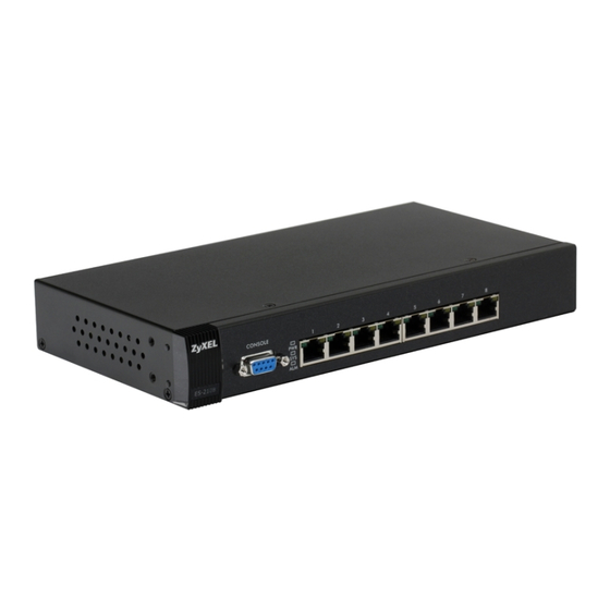
This chapter describes the front panel and rear panel of the Switch and shows you how to make the hardware connections. 3.1 Front Panel Connection The figure below shows the front panel of the Switch. Figure 10 Front Panel: ES-2108 Console Port 10/100 Mbps Ethernet Ports Figure 11 Front Panel: ES-2108-F... -
Page 42: Figure 12 Front Panel: Es-2108-G/Es-2108Pwr
Mini-GBIC Slot Use a mini-GBIC transceiver in this slot for a connection to a backbone Ethernet switch. 100 Base-FX This is a 100-Base FX fiber-optic module and is only available on the ES-2108-LC. Fiber-Optic Use the fiber optic cable to connect this uplink port to a backbone Ethernet switch. -
Page 43: Console Port
100Mbps Fast Ethernet, the speed can be 10Mbps or 100Mbps and the duplex mode can be half duplex or full duplex. The ES-2108-G and ES-2108PWR also come with a Gigabit/mini-GBIC slot each. The mini- GBIC slot has priority over the Gigabit port. This means that if the mini-GBIC slot and the corresponding Gigabit port are connected at the same time, the Gigabit port will be disabled. -
Page 44: Fast Ethernet Sfp Slot
Chapter 3 Hardware Overview 3.1.3 Fast Ethernet SFP Slot The ES-2108-F comes with a slot for 100-Base FX, 100-Base LX or 100-Base BX Small Form-Factor Pluggable (SFP) transceivers. A transceiver is a single unit that houses a transmitter and a receiver. The Switch does not come with transceivers. You must use transceivers that comply with the SFP Transceiver MultiSource Agreement (MSA). -
Page 45: Base-Fx Fiber-Optic Port
Figure 17 Transceiver Removal Example 3.1.5 100 Base-FX Fiber-Optic Port This 100 Base-FX fiber-optic port is only available on the ES-2108-LC. To avoid possible eye injury, do not look directly into a module’s fiber-optic connectors. Keep the dust cover on a fiber-optic module until you connect it. -
Page 46: Rear Panel
To connect the power to the DC powered version of the Switch, insert the female end of power adaptor’s cord into the power receptacle on the rear panel. Connect the power adaptor to an appropriate power source. ES-2108 Series User’s Guide... -
Page 47: Leds
The port is sending or receiving data. GBIC or Fast The port is not sending or receiving data. Ethernet SFP Slot) LNK (100 FX) Green The port has a successful connection. No Ethernet device is connected to this port. ES-2108 Series User’s Guide... - Page 48 Chapter 3 Hardware Overview Table 3 LEDs (continued) COLOR STATUS DESCRIPTION ACT (100 FX) Green Blinking The port is sending or receiving data. The port is not sending or receiving data. ES-2108 Series User’s Guide...
-
Page 49: Basic Configuration
Basic Configuration The Web Configurator (51) Initial Setup Example (61) System Status and Port Statistics (65) Basic Setting (71) -
Page 51: The Web Configurator
This section introduces the configuration and functions of the web configurator. This guide primarily uses the ES-2108G screen shots as an example. The screens may vary slightly for different ES-2108 models. Not all fields are available on all models. 4.1 Introduction The web configurator is an HTML-based management interface that allows easy Switch setup and management via Internet browser. -
Page 52: The Status Screen
B - Click this link to save your configuration into the Switch’s nonvolatile memory. Nonvolatile memory is the configuration of your Switch that stays the same even if the Switch’s power is turned off. C - Click this link to go to the status page of the Switch. ES-2108 Series User’s Guide... -
Page 53: Table 4 Navigation Panel Sub-Links Overview
E - Click this link to display web help pages. The help pages provide descriptions for all of the configuration screens. In the navigation panel, click a main link to reveal a list of submenu links. Table 4 Navigation Panel Sub-links Overview ADVANCED BASIC SETTING IP APPLICATION MANAGEMENT APPLICATION ES-2108 Series User’s Guide... -
Page 54: Table 5 Web Configurator Screen Sub-Links Details
Multicast Setting IGMP Snooping VLAN IGMP Filtering Profile Group Configuration Auth and Acct RADIUS Server Setup TACACS+ Server Setup Auth and Acct Setup IP Source Guard Static Binding ARP Inspection Log Status Configure Port VLAN Loop Guard ES-2108 Series User’s Guide... -
Page 55: Table 6 Navigation Panel Links
IP Source Guard This link takes you to a screen where you can configure filtering of unauthorized DHCP and ARP packets in your network. Loop Guard This link takes you to a screen where you can configure protection against network loops that occur on the edge of your network. IP Application ES-2108 Series User’s Guide... -
Page 56: Change Your Password
4.3.1 Change Your Password After you log in for the first time, it is recommended you change the default administrator password. Click Management > Access Control > Logins to display the next screen. ES-2108 Series User’s Guide... -
Page 57: Saving Your Configuration
1 Deleting the management VLAN (default is VLAN 1). 2 Deleting all port-based VLANs with the CPU port as a member. The “CPU port” is the management port of the Switch. 3 Filtering all traffic to the CPU port. 4 Disabling all ports. ES-2108 Series User’s Guide... -
Page 58: Resetting The Switch
” message. atlc Enter Debug Mode 5 Wait for the “ ” message before activating XMODEM Starting XMODEM upload upload on your terminal. 6 After the factory-default configuration file upload, type to restart the Switch. atgo ES-2108 Series User’s Guide... -
Page 59: Logging Out Of The Web Configurator
Chapter 4 The Web Configurator Figure 23 Resetting the Switch: Via the Console Port (ES-2108-G) Bootbase Version: V1.01 | 09/02/2005 14:00:16 RAM: Size = 32768 Kbytes DRAM POST: Testing: 32768K FLASH: AMD 32M *1 ZyNOS Version: V3.80(ABL.0)b2 | 05/28/2007 20:18:03 Press any key to enter debug mode within 3 seconds. - Page 60 Chapter 4 The Web Configurator ES-2108 Series User’s Guide...
-
Page 61: Initial Setup Example
VLANs confine broadcast frames to the VLAN group in which the port(s) belongs. You can do this with port-based VLAN or tagged static VLAN with fixed port members. In this example, you want to configure port 5 as a member of VLAN 2. Figure 25 Initial Setup Network Example: VLAN ES-2108 Series User’s Guide... - Page 62 TX Tagging check box to set the Switch to remove VLAN tags before sending. 5 Click Add to save the settings to the run-time memory. Settings in the run-time memory are lost when the Switch’s power is turned off. ES-2108 Series User’s Guide...
-
Page 63: Setting Port Vid
5.1.3 Configuring the Management IP Address The default management IP address of the Switch is 192.168.1.1. You can configure another IP address in a different subnet for management purposes. The following figure shows an example. ES-2108 Series User’s Guide... -
Page 64: Figure 27 Initial Setup Example: Management Ip Address
This is the same as the VLAN ID you configure in the Static VLAN screen. 6 Click Add to save your changes back to the run-time memory. Settings in the run-time memory are lost when the Switch’s power is turned off. ES-2108 Series User’s Guide... -
Page 65: System Status And Port Statistics
To view the port statistics, click Status in all web configurator screens to display the Status screen as shown next. The ES-2108PWR screen is different from the other models covered in this UG. The screen from ES-2108-G model is shown for comparison. Figure 28 Status (ES-2108PWR) ES-2108 Series User’s Guide... -
Page 66: Status: Port Details
Chapter 6 System Status and Port Statistics Figure 29 Status (ES-2108-G) The following table describes the labels in this screen. Table 7 Status LABEL DESCRIPTION Port This identifies the Ethernet port. Click a port number to display the Port Details... -
Page 67: Figure 30 Status: Port Details (Es-2108Pwr)
Chapter 6 System Status and Port Statistics The ES-2108PWR screen is different from the other models covered in this UG. The screen from ES-2108-G model is shown for comparison. Figure 30 Status: Port Details (ES-2108PWR) ES-2108 Series User’s Guide... -
Page 68: Figure 31 Status: Port Details (Es-2108-G)
Chapter 6 System Status and Port Statistics Figure 31 Status: Port Details (ES-2108-G) The following table describes the labels in this screen. Table 8 Status: Port Details LABEL DESCRIPTION Port Info Name This field shows the name of the port. - Page 69 Excessive collision is defined as the number of maximum collisions before the retransmission count is reset. Late This is the number of times a late collision is detected, that is, after 512 bits of the packets have already been transmitted. Error Packet ES-2108 Series User’s Guide...
- Page 70 This field shows the number of packets (including bad packets) received that were between 1024 and 1518 octets in length. Giant This field shows the number of packets dropped because they were bigger than the maximum frame size. ES-2108 Series User’s Guide...
-
Page 71: Basic Setting
Switch temperature, fan speeds and voltage (on the PWR model) in this screen. The ES-2108PWR screen is different from the other models covered in this UG. The screen from ES-2108-G model is shown for comparison. ES-2108 Series User’s Guide... -
Page 72: Figure 32 Basic Setting > System Info (Es-2108Pwr)
Chapter 7 Basic Setting Figure 32 Basic Setting > System Info (ES-2108PWR) Figure 33 Basic Setting > System Info (ES-2108-G) The following table describes the labels in this screen. Table 9 Basic Setting > System Info LABEL DESCRIPTION System Name This field displays the descriptive name of the Switch for identification purposes. -
Page 73: General Setup
Normal indicates that the voltage is within an acceptable operating range at this point; otherwise Error is displayed. 7.3 General Setup Use this screen to enter administrative details and time settings. Click Basic Setting > General Setup in the navigation panel to display the screen as shown. ES-2108 Series User’s Guide... -
Page 74: Figure 34 Basic Setting > General Setup
This field displays the time you open this menu (or refresh the menu). New Time Enter the new time in hour, minute and second format. The new time then appears (hh:min:ss) in the Current Time field after you click Apply. ES-2108 Series User’s Guide... -
Page 75: Introduction To Vlans
Devices on a logical network belong to one group. A device can belong to more than one group. With VLAN, a device cannot directly talk to or hear from devices that are not in the same group(s); the traffic must first go through a router. ES-2108 Series User’s Guide... -
Page 76: Switch Setup Screen
Click Basic Setting > Switch Setup in the navigation panel to display the screen as shown. The VLAN setup screens change depending on whether you choose 802.1Q or Port Based in the VLAN Type field in this screen. Refer to the chapter on VLAN. Figure 35 Basic Setting > Switch Setup ES-2108 Series User’s Guide... -
Page 77: Table 11 Basic Setting > Switch Setup
This is for “spare bandwidth”. Level 1 This is typically used for non-critical “background” traffic such as bulk transfers that are allowed but that should not affect other applications and users. Level 0 Typically used for best-effort traffic. ES-2108 Series User’s Guide... -
Page 78: Ip Setup
The factory default subnet mask is 255.255.255.0. You can configure up to 64 IP addresses which are used to access and manage the Switch from the ports belonging to the pre-defined VLAN(s). You must configure a VLAN first. ES-2108 Series User’s Guide... -
Page 79: Figure 36 Basic Setting > Ip Setup
Switch. You need to fill in the following fields when you select this option. Enter the IP address of your Switch in dotted decimal notation for example 192.168.1.1. Address Enter the IP subnet mask of your Switch in dotted decimal notation for example Subnet 255.255.255.0. Mask ES-2108 Series User’s Guide... -
Page 80: Port Setup
The Ethernet port must use the same speed or duplex mode setting as the peer Ethernet port in order to connect. ES-2108 Series User’s Guide... -
Page 81: Figure 37 Basic Setting > Port Setup (Es-2108Pwr)
The ES-2108PWR screen is different from the other models covered in this UG. The screen from ES-2108-G model is shown for comparison. Figure 37 Basic Setting > Port Setup (ES-2108PWR) ES-2108 Series User’s Guide... -
Page 82: Figure 38 Basic Setting > Port Setup (Es-2108-G)
This field displays 10/100M for an Ethernet connection and 10/100/1000M for the Gigabit Ethernet/mini-GBIC slots and 100M for a 100 base-FX fiber-optic port on the ES-2108-LC or a Fast Ethernet SFP transceiver connection on the ES-2108-F. ES-2108 Series User’s Guide... - Page 83 For the mini-GBIC slot on the ES-2108-LC, select Auto or 1000M/Full Duplex. The port speed and the duplex mode are fixed (100M/Full Duplex) for the 100 Base- FX fiber optic port on the ES-2108-LC and the Fast Ethernet SFP transceiver connection on the ES-2108-F.
- Page 84 Chapter 7 Basic Setting ES-2108 Series User’s Guide...
-
Page 85: Advanced Setup
Advanced Setup VLAN (87) Static MAC Forwarding (97) Filtering (99) Spanning Tree Protocol (101) Bandwidth Control (115) Broadcast Storm Control (117) Mirroring (119) Link Aggregation (121) Port Authentication (127) Port Security (131) Queuing Method (135) Multicast (137) Authentication & Accounting (151) IP Source Guard (165) Loop Guard (175) -
Page 87: Vlan
802.1Q VLAN-unaware switch to an 802.1Q VLAN-aware switch, the Switch first decides where to forward the frame, and then inserts a VLAN tag reflecting the ingress port's default VID. The default PVID is VLAN 1 for all ports, but this can be changed. ES-2108 Series User’s Guide... -
Page 88: Automatic Vlan Registration
You may choose to accept both tagged and untagged type incoming frames or just tagged incoming frames on a port. Ingress filtering If set, the Switch discards incoming frames for VLANs that do not have this port as a member ES-2108 Series User’s Guide... -
Page 89: Port Vlan Trunking
• sent to a group whether it has a VLAN tag or not. • blocked from a VLAN group regardless of its VLAN tag. You can also tag all outgoing frames (that were previously untagged) from a port with the specified VID. ES-2108 Series User’s Guide... -
Page 90: Static Vlan Status
Use this screen to view detailed port settings and status of the VLAN group. See Section 8.1 on page 87 for more information on static VLANs. Click on an index number in the VLAN Status screen to display VLAN details. Figure 42 Advanced Application > VLAN > VLAN Detail ES-2108 Series User’s Guide... -
Page 91: Configure A Static Vlan
8.5 on page 89 for more information on static VLAN. To configure a static VLAN, click Static VLAN in the VLAN Status screen to display the screen as shown next. Figure 43 Advanced Application > VLAN > Static VLAN ES-2108 Series User’s Guide... -
Page 92: Configure Vlan Port Settings
Use the VLAN Port Setting screen to configure the static VLAN (IEEE 802.1Q) settings on a port. See Section 8.5 on page 89 for more information on static VLAN. Click the VLAN Port Setting link in the VLAN Status screen. ES-2108 Series User’s Guide... -
Page 93: Figure 44 Advanced Application > Vlan > Vlan Port Setting
VLAN Trunking Enable VLAN Trunking on ports connected to other switches or routers (but not ports directly connected to end users) to allow frames belonging to unknown VLAN groups to pass through the Switch. ES-2108 Series User’s Guide... -
Page 94: Port Based Vlan Setup
8.6.1 Configure a Port-based VLAN Select Port Based as the VLAN Type in the Switch Setup screen (see Figure 40 on page and then click Advanced Application > VLAN in the navigation panel to display the next screen. ES-2108 Series User’s Guide... -
Page 95: Figure 45 Advanced Application > Vlan: Port Based Vlan Setup (All Connected)
Chapter 8 VLAN Figure 45 Advanced Application > VLAN: Port Based VLAN Setup (All Connected) Figure 46 Advanced Application > VLAN: Port Based VLAN Setup (Port Isolation) ES-2108 Series User’s Guide... -
Page 96: Table 19 Advanced Application > Vlan: Port Based Vlan Setup
Save link on the top navigation panel to save your changes to the non-volatile memory when you are done configuring. Cancel Click Cancel to start configuring the screen again. ES-2108 Series User’s Guide... -
Page 97: Static Mac Forwarding
Switch. See Chapter 17 on page 131 for more information on port security. Click Advanced Applications > Static MAC Forwarding in the navigation panel to display the configuration screen as shown. ES-2108 Series User’s Guide... -
Page 98: Figure 47 Advanced Application > Static Mac Forwarding
This field displays the port where the MAC address shown in the next field will be forwarded. Delete Click Delete to remove the selected entry from the summary table. Cancel Click Cancel to clear the Delete check boxes. ES-2108 Series User’s Guide... -
Page 99: Filtering
VID field are dropped by the Switch. Type the VLAN group identification number. Packets which match the VLAN identification number and the MAC address you enter in the MAC field are dropped by the Switch. ES-2108 Series User’s Guide... - Page 100 This field displays the VLAN group identification number. Delete Check the rule(s) that you want to remove in the Delete column and then click the Delete button. Cancel Click Cancel to clear the selected check box(es) in the Delete column. ES-2108 Series User’s Guide...
-
Page 101: Spanning Tree Protocol
Both RSTP and STP flush unwanted learned addresses from the filtering database. In RSTP, the port states are Discarding, Learning, and Forwarding. In this user’s guide, “STP” refers to both STP and RSTP. 11.1.1 STP Terminology The root bridge is the base of the spanning tree. ES-2108 Series User’s Guide... -
Page 102: How Stp Works
BPDU after a predefined interval (Max Age), the bridge assumes that the link to the root bridge is down. This bridge then initiates negotiations with other bridges to reconfigure the network to re-establish a valid network topology. ES-2108 Series User’s Guide... -
Page 103: Stp Port States
The following figure shows a network example where two VLANs are configured on the two switches. If the switches are using STP or RSTP, the link for VLAN 2 will be blocked as STP and RSTP allow only one link in the network and block the redundant link. ES-2108 Series User’s Guide... -
Page 104: Figure 49 Stp/Rstp Network Example
Devices that belong to the same MST region are configured to have the same MSTP configuration identification settings. These include the following parameters: • Name of the MST region • Revision level as the unique number for the MST region ES-2108 Series User’s Guide... -
Page 105: Figure 51 Mstis In Different Regions
MST instance are members of the CIST. In an MSTP-enabled network, there is only one CIST that runs between MST regions and single spanning tree devices. A network may contain multiple MST regions and other network segments running RSTP. Figure 52 MSTP and Legacy RSTP Network Example ES-2108 Series User’s Guide... -
Page 106: Spanning Tree Protocol Status Screen
Save link on the top navigation panel to save your changes to the non-volatile memory when you are done configuring. Cancel Click Cancel to begin configuring this screen afresh. ES-2108 Series User’s Guide... -
Page 107: Configure Rapid Spanning Tree Protocol
Bridge Priority determines the root bridge, which in turn determines Hello Time, Max Age and Forwarding Delay. Hello Time This is the time interval in seconds between BPDU (Bridge Protocol Data Units) configuration message generations by the root switch. The allowed range is 1 to 10 seconds. ES-2108 Series User’s Guide... -
Page 108: Rapid Spanning Tree Protocol Status
Click Advanced Application > Spanning Tree Protocol in the navigation panel to display the status screen as shown next. See Section 11.1 on page 101 for more information on RSTP. This screen is only available after you activate RSTP on the Switch. ES-2108 Series User’s Guide... -
Page 109: Configure Multiple Spanning Tree Protocol
This is the time since the spanning tree was last reconfigured. Change 11.6 Configure Multiple Spanning Tree Protocol To configure MSTP, click MSTP in the Advanced Application > Spanning Tree Protocol screen. See Section 11.1.4 on page 103 for more information on MSTP. ES-2108 Series User’s Guide... -
Page 110: Figure 57 Advanced Application > Spanning Tree Protocol > Mstp
Chapter 11 Spanning Tree Protocol Figure 57 Advanced Application > Spanning Tree Protocol > MSTP ES-2108 Series User’s Guide... -
Page 111: Table 27 Advanced Application > Spanning Tree Protocol > Mstp
Switch will be chosen as the root bridge within the spanning tree instance. Enter priority values between 0 and 61440 in increments of 4096 (thus valid values are 0, 4096, 8192, 12288, 16384, 20480, 24576, 28672, 32768, 36864, 40960, 45056, 49152, 53248, 57344 and 61440). ES-2108 Series User’s Guide... -
Page 112: Multiple Spanning Tree Protocol Status
11.7 Multiple Spanning Tree Protocol Status Click Advanced Application > Spanning Tree Protocol in the navigation panel to display the status screen as shown next. See Section 11.1.4 on page 103 for more information on MSTP. ES-2108 Series User’s Guide... -
Page 113: Figure 58 Advanced Application > Spanning Tree Protocol: Status, Mstp
This is the time interval (in seconds) at which the root switch transmits a (second) configuration message. Max Age (second) This is the maximum time (in seconds) a switch can wait without receiving a configuration message before attempting to reconfigure. ES-2108 Series User’s Guide... - Page 114 This is the path cost from the root port in this MST instance to the regional root switch. Port ID This is the priority and number of the port on the Switch through which this Switch must communicate with the root of the MST instance. ES-2108 Series User’s Guide...
-
Page 115: Bandwidth Control
The following table describes the related labels in this screen. Table 29 Advanced Application > Bandwidth Control LABEL DESCRIPTION Active Select this check box to enable bandwidth control on the Switch. Port This field displays the port number. ES-2108 Series User’s Guide... - Page 116 Save link on the top navigation panel to save your changes to the non-volatile memory when you are done configuring. Cancel Click Cancel to reset the fields to your previous configuration. ES-2108 Series User’s Guide...
-
Page 117: Broadcast Storm Control
Table 30 Advanced Application > Broadcast Storm Control LABEL DESCRIPTION Active Select this check box to enable broadcast storm control on the Switch. Clear this check box to disable the feature. Port This field displays a port number. ES-2108 Series User’s Guide... - Page 118 Save link on the top navigation panel to save your changes to the non-volatile memory when you are done configuring. Cancel Click Cancel to begin configuring this screen afresh. ES-2108 Series User’s Guide...
-
Page 119: Mirroring
The monitor port is the port you copy the traffic to in order to examine it in more detail Port without interfering with the traffic flow on the original port(s). Select this port from this drop-down list box. ES-2108 Series User’s Guide... - Page 120 Save link on the top navigation panel to save your changes to the non-volatile memory when you are done configuring. Cancel Click Cancel to start configuring the screen again. ES-2108 Series User’s Guide...
-
Page 121: Link Aggregation
• All ports in the same trunk group must have the same media type, speed, duplex mode and flow control settings. Configure trunk groups or LACP before you connect the Ethernet switches to avoid causing network topology loops. ES-2108 Series User’s Guide... -
Page 122: Link Aggregation Id
• LACP - if the ports are configured to join a trunk group via LACP. Port Priority and Port Number are 0 as it is the aggregator ID for the trunk group, not the individual port. ES-2108 Series User’s Guide... -
Page 123: Link Aggregation Setup
Save link on the top navigation panel to save your changes to the non-volatile memory when you are done configuring. Cancel Click Cancel to begin configuring this screen afresh. ES-2108 Series User’s Guide... -
Page 124: Link Aggregation Control Protocol
(LACP). The smaller the number, the higher the priority level. Group ID The field identifies the link aggregation group, that is, one logical link containing multiple ports. LACP Active Select this option to enable LACP for a trunk. Port This field displays the port number. ES-2108 Series User’s Guide... -
Page 125: Static Trunking Example
2 Configure static trunking - Click Advanced Application > Link Aggregation > Link Aggregation Setting. In this screen activate trunking group T1 and select the ports that should belong to this group as shown in the figure below. Click Apply when you are done. ES-2108 Series User’s Guide... -
Page 126: Figure 66 Trunking Example - Configuration Screen
Chapter 15 Link Aggregation Figure 66 Trunking Example - Configuration Screen Your trunk group 1 (T1) configuration is now complete; you do not need to go to any additional screens. ES-2108 Series User’s Guide... -
Page 127: Port Authentication
At the time of writing, IEEE 802.1x is not supported by all operating systems. See your operating system documentation. If your operating system does not support 802.1x, then you may need to install 802.1x client software. ES-2108 Series User’s Guide... -
Page 128: Port Authentication Configuration
Click Advanced Application > Port Authentication in the navigation panel to display the screen as shown. Figure 68 Advanced Application > Port Authentication 16.2.1 Activate IEEE 802.1x Security Use this screen to activate IEEE 802.1x security. From the Port Authentication screen, display the configuration screen as shown. ES-2108 Series User’s Guide... -
Page 129: Figure 69 Advanced Application > Port Authentication > 802.1X
Save link on the top navigation panel to save your changes to the non-volatile memory when you are done configuring. Cancel Click Cancel to begin configuring this screen afresh. ES-2108 Series User’s Guide... - Page 130 Chapter 16 Port Authentication ES-2108 Series User’s Guide...
-
Page 131: Port Security
• Drop all packets from unknown MAC addresses and do not learn MAC addresses. • Drop all packets from unknown MAC addresses and learn a limited number of MAC addresses. The ES-2108 Series supports five possible configurations for port security. Section 17.3 on page 133 for supported configurations and an example. -
Page 132: Figure 70 Advanced Application > Port Security
MAC addresses aged out. MAC address aging out time can be set in the Switch Setup screen. The valid range is from “0” to “8192”. “0” means that the limiting of learned addresses is disabled. ES-2108 Series User’s Guide... -
Page 133: Port Security Example
• Port 4 - Drop all packets from unknown MAC addresses and do not learn MAC addresses. • Port 5 - Drop all packets from unknown MAC addresses but forward packets from up to 100 learned MAC addresses. Figure 71 Port Security Example ES-2108 Series User’s Guide... -
Page 134: Table 39 Port Security Example
Drop all packets from unknown MAC addresses, do not learn MAC addresses. Drop all packets from unknown MAC addresses, do not learn MAC addresses. Drop packets from unknown MAC addresses, learn up to 100 MAC addresses. ES-2108 Series User’s Guide... -
Page 135: Queuing Method
This works in a looping fashion until a queue is empty. ES-2108 Series User’s Guide... -
Page 136: Configuring Queuing Method
Save link on the top navigation panel to save your changes to the non-volatile memory when you are done configuring. Cancel Click Cancel to begin configuring this screen afresh. ES-2108 Series User’s Guide... -
Page 137: Multicast
IP multicast hosts to learn the IP multicast group membership. It checks IGMP packets passing through it, picks out the group registration information, and configures multicasting accordingly. IGMP snooping allows the Switch to learn multicast groups without you having to manually configure them. ES-2108 Series User’s Guide... -
Page 138: Igmp Snooping And Vlans
This field displays IP multicast group addresses. 19.3 Multicast Setting Click Advanced Application > Multicast > Multicast Setting link to display the screen as shown. See Section 19.1 on page 137 for more information on multicasting. ES-2108 Series User’s Guide... -
Page 139: Figure 74 Advanced Application > Multicast > Multicast Setting
Select a priority level (0-7) to which the Switch changes the priority in outgoing IGMP control packets. Otherwise, select No-Change to not replace the priority. IGMP Filtering Select Active to enable IGMP filtering to control which IGMP groups a subscriber on a port can join. ES-2108 Series User’s Guide... -
Page 140: Igmp Snooping Vlan
19.4 IGMP Snooping VLAN Click Advanced Application > Multicast > Multicast Setting > IGMP Snooping VLAN link to display the screen as shown. See Section 19.1.4 on page 138 for more information on IGMP Snooping VLAN. ES-2108 Series User’s Guide... -
Page 141: Figure 75 Advanced Application > Multicast > Multicast Setting > Igmp Snooping Vlan
Switch’s run-time memory. The Switch loses these changes if it is turned off or loses power, so use the Save link on the top navigation panel to save your changes to the non-volatile memory when you are done configuring. ES-2108 Series User’s Guide... -
Page 142: Igmp Filtering Profile
To configure additional rule(s) for a profile that you have already added, enter the profile name and specify a different IP multicast address range. Start Address Type the starting multicast IP address for a range of multicast IP addresses that you want to belong to the IGMP filter profile. ES-2108 Series User’s Guide... -
Page 143: Mvr Overview
The following figure shows a network example. The subscriber VLAN (1, 2 and 3) information is hidden from the streaming media server, S. In addition, the multicast VLAN information is only visible to the Switch and S. Figure 77 MVR Network Example ES-2108 Series User’s Guide... -
Page 144: Types Of Mvr Ports
VLAN, the receiving port will still be on the list of forwarding destination for the multicast traffic. Otherwise, the Switch removes the receiver port from the forwarding table. Figure 78 MVR Multicast Television Example ES-2108 Series User’s Guide... -
Page 145: General Mvr Configuration
Select this check box to enable MVR to allow one single multicast VLAN to be shared among different subscriber VLANs on the network. Name Enter a descriptive name (up to 32 printable ASCII characters) for identification purposes. ES-2108 Series User’s Guide... -
Page 146: Mvr Group Configuration
Delete column, then click the Delete button. Cancel Click Cancel to clear the Delete check boxes. 19.8 MVR Group Configuration All source ports and receiver ports belonging to a multicast group can receive multicast data sent to this multicast group. ES-2108 Series User’s Guide... -
Page 147: Figure 80 Advanced Application > Multicast > Multicast Setting > Mvr > Group Configuration
Name This field displays the descriptive name for this setting. Start Address This field displays the starting IP address of the multicast group. End Address This field displays the ending IP address of the multicast group. ES-2108 Series User’s Guide... -
Page 148: Mvr Configuration Example
A, B and C in VLAN 1 are able to receive the traffic. Figure 81 MVR Configuration Example To configure the MVR settings on the Switch, create a multicast group in the MVR screen and set the receiver and source ports. ES-2108 Series User’s Guide... -
Page 149: Figure 82 Mvr Configuration Example
To set the Switch to forward the multicast group traffic to the subscribers, configure multicast group settings in the Group Configuration screen. The following figure shows an example where two multicast groups (News and Movie) are configured for the multicast VLAN 200. Figure 83 MVR Group Configuration Example ES-2108 Series User’s Guide... -
Page 150: Figure 84 Mvr Group Configuration Example
Chapter 19 Multicast Figure 84 MVR Group Configuration Example ES-2108 Series User’s Guide... -
Page 151: Authentication & Accounting
By storing user profiles locally on the Switch, your Switch is able to authenticate and authorize users without interacting with a network AAA server. However, there is a limit on the number of users you may authenticate in this way (See Chapter 27 on page 203). ES-2108 Series User’s Guide... -
Page 152: Radius And Tacacs
Section 20.3 on page 160 for RADIUS attributes utilized by the authentication and accounting features on the Switch. Click on the RADIUS Server Setup link in the Authentication and Accounting screen to view the screen as shown. ES-2108 Series User’s Guide... -
Page 153: Figure 87 Advanced Application > Auth And Acct > Radius Server Setup
Specify a password (up to 32 alphanumeric characters) as the key to be shared between the external RADIUS server and the Switch. This key is not sent over the network. This key must be the same on the external RADIUS server and the Switch. ES-2108 Series User’s Guide... -
Page 154: Tacacs+ Server Setup
Use this screen to configure your TACACS+ server settings. See Section 20.1.2 on page 152 for more information on TACACS+ servers. Click on the TACACS+ Server Setup link in the Authentication and Accounting screen to view the screen as shown. ES-2108 Series User’s Guide... -
Page 155: Figure 88 Advanced Application > Auth And Acct > Tacacs+ Server Setup
Enter the IP address of an external TACACS+ server in dotted decimal notation. TCP Port The default port of a TACACS+ server for authentication is 49. You need not change this value unless your network administrator instructs you to do so. ES-2108 Series User’s Guide... -
Page 156: Authentication And Accounting Setup
20.2.3 Authentication and Accounting Setup Use this screen to configure authentication and accounting settings on the Switch. Click on the Auth and Acct Setup link in the Authentication and Accounting screen to view the screen as shown. ES-2108 Series User’s Guide... -
Page 157: Figure 89 Advanced Application > Auth And Acct > Auth And Acct Setup
Select local to have the Switch check the access privilege configured for local authentication. Select radius to have the Switch authenticate the administrator accounts through a RADIUS server. Select tacacs+ to have the Switch authenticate the administrator accounts through a TACACS+ server. ES-2108 Series User’s Guide... - Page 158 This field is only configurable for Commands type of event. Select the threshold command privilege level for which the Switch should send accounting information. The Switch will send accounting information when commands at the level you specify and higher are executed on the Switch. ES-2108 Series User’s Guide...
-
Page 159: Vendor Specific Attribute
The VSAs are composed of the following: • Vendor-ID: An identification number assigned to the company by the IANA (Internet Assigned Numbers Authority). ZyXEL’s vendor ID is 890. • Vendor-Type: A vendor specified attribute, identifying the setting you want to modify. -
Page 160: Supported Radius Attributes
Refer to RFC 2866 and RFC 2869 for RADIUS attributes used for accounting. This section lists the attributes used by authentication and accounting functions on the Switch. In cases where the attribute has a specific format associated with it, the format is specified. ES-2108 Series User’s Guide... -
Page 161: Attributes Used For Authentication
The following sections list the attributes sent from the Switch to the RADIUS server when performing authentication. 20.3.2.1 Attributes Used for Accounting System Events NAS-IP-Address NAS-Identifier Acct-Status-Type Acct-Session-ID - The format of Acct-Session-Id is date+time+8-digit sequential number, for example, 2007041917210300000001. (date: 2007/04/19, time: 17:21:03, serial number: 00000001) Acct-Delay-Time ES-2108 Series User’s Guide... -
Page 162: Table 54 Radius Attributes - Exec Events Via Console
The attributes are listed in the following table along with the time of the session they are sent: Table 56 RADIUS Attributes - Exec Events via Console ATTRIBUTE START INTERIM-UPDATE STOP User-Name NAS-IP-Address NAS-Port Class Called-Station-Id Calling-Station-Id NAS-Identifier ES-2108 Series User’s Guide... - Page 163 Chapter 20 Authentication & Accounting Table 56 RADIUS Attributes - Exec Events via Console ATTRIBUTE START INTERIM-UPDATE STOP NAS-Port-Type Acct-Status-Type Acct-Delay-Time Acct-Session-Id Acct-Authentic Acct-Input-Octets Acct-Output-Octets Acct-Session-Time Acct-Input-Packets Acct-Output-Packets Acct-Terminate-Cause Acct-Input-Gigawords Acct-Output-Gigawords ES-2108 Series User’s Guide...
- Page 164 Chapter 20 Authentication & Accounting ES-2108 Series User’s Guide...
-
Page 165: Ip Source Guard
21.1.1 ARP Inspection Overview Use ARP inspection to filter unauthorized ARP packets on the network. This can prevent many kinds of man-in-the-middle attacks, such as the one in the following example. Figure 90 Example: Man-in-the-middle Attack ES-2108 Series User’s Guide... - Page 166 ARP packets. 2 Enable ARP inspection on the Switch. 3 Enable ARP inspection on each VLAN. 4 Configure trusted and untrusted ports, and specify the maximum number of ARP packets that each port can receive per second. ES-2108 Series User’s Guide...
-
Page 167: Ip Source Guard
If you try to create a static binding with the same MAC address and VLAN ID as an existing static binding, the new static binding replaces the original one. To open this screen, click Advanced Application > IP Source Guard > Static Binding. ES-2108 Series User’s Guide... -
Page 168: Figure 92 Advanced Application > Ip Source Guard > Static Binding
This field displays the port number in the binding. If this field is blank, the binding applies to all ports. Delete Select this, and click Delete to remove the specified entry. Cancel Click this to clear the Delete check boxes above. ES-2108 Series User’s Guide... -
Page 169: Arp Inspection Status
Use this screen to look at log messages that were generated by ARP packets and that have not been sent to the syslog server yet. To open this screen, click Advanced Application > IP Source Guard > ARP Inspection > Log Status. ES-2108 Series User’s Guide... -
Page 170: Arp Inspection Configure
Use this screen to enable ARP inspection on the Switch. You can also configure the length of time the Switch stores records of discarded ARP packets and global settings for the ARP inspection log. To open this screen, click Advanced Application > IP Source Guard > ARP Inspection > Configure. ES-2108 Series User’s Guide... -
Page 171: Figure 95 Advanced Application > Ip Source Guard > Arp Inspection > Configure
Click Clearing log status table in the ARP Inspection Log Status screen to clear the log and reset this counter. See Section 21.4.1 on page 169. ES-2108 Series User’s Guide... -
Page 172: Arp Inspection Port Configure
Use this screen to specify whether ports are trusted or untrusted ports for ARP inspection. To open this screen, click Advanced Application > IP Source Guard > ARP Inspection > Configure > Port. Figure 96 Advanced Application > IP Source Guard > ARP Inspection > Configure > Port ES-2108 Series User’s Guide... -
Page 173: Arp Inspection Vlan Configure
This field displays the VLAN ID of each VLAN in the range specified above. If you configure the * VLAN, the settings are applied to all VLANs. Enabled Select Yes to enable ARP inspection on the VLAN. Select No to disable ARP inspection on the VLAN. ES-2108 Series User’s Guide... - Page 174 Switch loses these changes if it is turned off or loses power, so use the Save link on the top navigation panel to save your changes to the non- volatile memory when you are done configuring. Cancel Click this to reset the values in this screen to their last-saved values. ES-2108 Series User’s Guide...
-
Page 175: Loop Guard
• It will receive broadcast messages sent out from the switch in loop state. • It will receive its own broadcast messages that it sends out as they loop back. It will then re-broadcast those messages again. ES-2108 Series User’s Guide... -
Page 176: Figure 99 Switch In Loop State
In this example, the probe packet is sent from port N and returns on another port. As long as loop guard is enabled on port N. The Switch will shut down port N if it detects that the probe packet has returned to the Switch. Figure 101 Loop Guard - Network Loop ES-2108 Series User’s Guide... -
Page 177: Loop Guard Setup
Select this option to enable loop guard on the Switch. The Switch generates syslog, internal log messages as well as SNMP traps when it shuts down a port via the loop guard feature. Port This field displays a port number. ES-2108 Series User’s Guide... - Page 178 Save link on the top navigation panel to save your changes to the non-volatile memory when you are done configuring. Cancel Click Cancel to begin configuring this screen afresh. ES-2108 Series User’s Guide...
-
Page 179: Ip Application
IP Application Static Route (181) Differentiated Services (185) DHCP (189) -
Page 181: Static Route
R2 to send traffic to an SNMP trap server on network N2. Figure 103 Static Routing Overview SNMP Telnet 23.2 Configuring Static Routing Click IP Application > Static Routing in the navigation panel to display the screen as shown. ES-2108 Series User’s Guide... -
Page 182: Figure 104 Ip Application > Static Routing
This field displays the index number of the route. Click a number to edit the static route entry. Active This field displays Yes when the static route is activated and NO when it is deactivated. Name This field displays the descriptive name for this route. This is for identification purpose only. ES-2108 Series User’s Guide... - Page 183 Switch that will forward the packet to the destination. Metric This field displays the cost of transmission for routing purposes. Delete Click Delete to remove the selected entry from the summary table. Cancel Click Cancel to clear the Delete check boxes. ES-2108 Series User’s Guide...
- Page 184 Chapter 23 Static Route ES-2108 Series User’s Guide...
-
Page 185: Differentiated Services
Resources can then be allocated according to the DSCP values and the configured policies. 24.1.2 DiffServ Network Example The following figure depicts a simple DiffServ network consisting of a group of contiguous DiffServ-compliant network devices. ES-2108 Series User’s Guide... -
Page 186: Activating Diffserv
The following table describes the labels in this screen. Table 66 IP Application > DiffServ LABEL DESCRIPTION Active Select this option to enable DiffServ on the Switch. Port This field displays the index number of a port on the Switch. ES-2108 Series User’s Guide... -
Page 187: Dscp-To-Ieee802.1P Priority Mapping Settings
24.3.1 Configuring DSCP Settings Use this screen to change the DSCP-IEEE 802.1p mapping click the DSCP Setting link in the DiffServ screen to display the screen as shown next. Figure 108 IP Application > DiffServ > DSCP Setting ES-2108 Series User’s Guide... -
Page 188: Table 68 Ip Application > Diffserv > Dscp Setting
Save link on the top navigation panel to save your changes to the non-volatile memory when you are done configuring. Cancel Click Cancel to discard all changes and start configuring the screen again. ES-2108 Series User’s Guide... -
Page 189: Dhcp
• VLAN - The Switch is configured on a VLAN by VLAN basis. The Switch can be configured to relay DHCP requests to different DHCP servers for clients in different VLAN. 25.2 DHCP Status Click IP Application > DHCP in the navigation panel to open the following screen. ES-2108 Series User’s Guide... -
Page 190: Dhcp Relay
Table 70 Relay Agent Information FIELD LABELS DESCRIPTION Slot ID (1 byte) This value is always 0 for stand-alone switches. Port ID (1 byte) This is the port that the DHCP client is connected to. ES-2108 Series User’s Guide... -
Page 191: Configuring Dhcp Global Relay
Save link on the top navigation panel to save your changes to the non-volatile memory when you are done configuring. Cancel Click Cancel to begin configuring this screen afresh. ES-2108 Series User’s Guide... -
Page 192: Global Dhcp Relay Configuration Example
Use this screen to configure your DHCP settings based on the VLAN domain of the DHCP clients. Click IP Application > DHCP in the navigation panel, then click the VLAN link In the DHCP Status screen that displays. ES-2108 Series User’s Guide... -
Page 193: Figure 113 Ip Application > Dhcp > Vlan
Click Cancel to begin configuring this screen afresh. Clear Click this to clear the fields above. This field displays the ID number of the VLAN group to which this DHCP settings apply. Type This field displays the DHCP mode (Relay). ES-2108 Series User’s Guide... -
Page 194: Example: Dhcp Relay For Two Vlans
IP address of 172.23.10.100. Figure 114 DHCP Relay for Two VLANs DHCP:192.168.1.100 VLAN 1 VLAN 2 DHCP:172.23.10.100 For the example network, configure the VLAN Setting screen as shown. Figure 115 DHCP Relay for Two VLANs Configuration Example ES-2108 Series User’s Guide... -
Page 195: Management
Management Maintenance (197) Access Control (203) Diagnostic (221) Syslog (223) Cluster Management (227) (233) ARP Table (235) Configure Clone (237) -
Page 197: Maintenance
If you want to access the Switch web configurator again, you may need to change the IP address of your computer to be in the same subnet as that of the default Switch IP address (192.168.1.1). ES-2108 Series User’s Guide... -
Page 198: Load Factory Default
Switch’s non-volatile memory. These settings are not lost when you restart the Switch. Alternatively, you can click the Save button on the top right corner of the web configurator to save your settings to the Switch’s non-volatile memory. ES-2108 Series User’s Guide... -
Page 199: Reboot System
After the firmware upgrade process is complete, see the System Info screen to verify your current firmware version number. 26.6 Restore a Configuration File Use this screen to restore a previously saved configuration from your computer to the Switch. ES-2108 Series User’s Guide... -
Page 200: Backup Configuration File
File name list box. Click Save to save the configuration file to your computer. 26.8 FTP Command Line This section shows some examples of uploading to or downloading files from the Switch using FTP commands. First, understand the filename conventions. ES-2108 Series User’s Guide... -
Page 201: Filename Conventions
(as a plain text file) back to your computer under a filename of your choosing. ZyNOS (ZyXEL Network Operating System sometimes referred to as the “ras” file) is the system firmware and has a “bin” filename extension. -
Page 202: Gui-Based Ftp Clients
• FTP service is disabled in the Access Control screen. • The IP address(es) in the Secured Client Set in the Remote Management screen does not match the client IP address. If it does not match, the Switch will disallow the session. ES-2108 Series User’s Guide... -
Page 203: Access Control
27.2 The Access Control Main Screen Click Management, Access Control in the navigation panel to display the main screen as shown. Figure 121 Access Control Use these links to configure remote management options and create user accounts on the Switch. ES-2108 Series User’s Guide... -
Page 204: About Snmp
Get operation, followed by a series of Get Next operations. Allows the manager to set values for object variables within an agent. Trap Used by the agent to inform the manager of some events. ES-2108 Series User’s Guide... -
Page 205: Snmp V3 And Security
The Switch sends traps to an SNMP manager when an event occurs. This table lists the beginnings of the private MIB trap OIDs for the various ES-2108 models. An OID (Object ID) that begins with one of the numbers listed here is defined in the related model’s private MIBs. -
Page 206: Table 80 Snmp Interface Traps
1.3.6.1.4.1.890.1.5.8.xx.31.2.2 This trap is sent when the Ethernet link is up. linkdown linkDown 1.3.6.1.6.3.1.1.5.3 This trap is sent when the Ethernet link is down. LinkDownEventOn 1.3.6.1.4.1.890.1.5.8.xx.31.2.1 This trap is sent when the Ethernet link is down. ES-2108 Series User’s Guide... -
Page 207: Table 81 Aaa Traps
This trap is sent when a single ping probe fails. pingTestFailed 1.3.6.1.2.1.80.0.2 This trap is sent when a ping test (consisting of a series of ping probes) fails. pingTestCompleted 1.3.6.1.2.1.80.0.3 This trap is sent when a ping test is completed. ES-2108 Series User’s Guide... -
Page 208: Configuring Snmp
This trap is sent when the variable falls below the RMON "falling" threshold. 27.3.4 Configuring SNMP From the Access Control screen, display the SNMP screen. You can click Access Control to go back to the Access Control screen. ES-2108 Series User’s Guide... -
Page 209: Figure 123 Management > Access Control > Snmp
Use this section to configure where to send SNMP traps from the Switch. Version Specify the version of the SNMP trap messages. Enter the IP addresses of up to four managers to send your SNMP traps to. ES-2108 Series User’s Guide... -
Page 210: Configuring Snmp Trap Group
27.3.5 Configuring SNMP Trap Group From the SNMP screen, click Trap Group to view the screen as shown. Use the Trap Group screen to specify the types of SNMP traps that should be sent to each SNMP manager. ES-2108 Series User’s Guide... -
Page 211: Setting Up Login Accounts
Up to five people (one administrator and four non-administrators) may access the Switch via web configurator at any one time. • An administrator is someone who can both view and configure Switch changes. The username for the Administrator is always admin. The default administrator password is 1234. ES-2108 Series User’s Guide... -
Page 212: Figure 125 Management > Access Control > Logins
You may configure passwords for up to four users. These people have read-only access. User Name Set a user name (up to 30 characters long). Password Enter your new system password. Retype to confirm Retype your new system password for confirmation ES-2108 Series User’s Guide... -
Page 213: Ssh Overview
Figure 126 SSH Communication Example 27.6 How SSH works The following table summarizes how a secure connection is established between two remote hosts. ES-2108 Series User’s Guide... -
Page 214: Ssh Implementation On The Switch
22. Only one SSH connection is allowed at a time. 27.7.1 Requirements for Using SSH You must install an SSH client program on a client computer (Windows or Linux operating system) that is used to connect to the Switch over SSH. ES-2108 Series User’s Guide... -
Page 215: Ssh Login Example
SSH/hostkeys/key_22_192.168.1.1.pub host key for 192.168.1.1, accepted by Administrator Thu May 12 2005 09:52:21 admin's password: Authentication successful. Copyright (c) 1994 - 2006 ZyXEL Communications Corp. ras> 27.8 Introduction to HTTPS HTTPS (Hyper Text Transfer Protocol over Secure Socket Layer, or HTTP over SSL) is a web protocol that encrypts and decrypts web pages. -
Page 216: Https Example
Click View Certificate if you want to verify that the certificate is from the Switch. You see the following Security Alert screen in Internet Explorer. Select Yes to proceed to the web configurator login screen; if you select No, then web configurator access is blocked. ES-2108 Series User’s Guide... -
Page 217: Netscape Navigator Warning Messages
If Accept this certificate temporarily for this session is selected, then click OK to continue in Netscape. Select Accept this certificate permanently to import the Switch’s certificate into the SSL client. Figure 131 Security Certificate 1 (Netscape) ES-2108 Series User’s Guide... -
Page 218: The Main Screen
Service Access Control allows you to decide what services you may use to access the Switch. You may also change the default service port and configure “trusted computer(s)” for each service in the Remote Management screen (discussed later). Click Access Control to go back to the main Access Control screen. ES-2108 Series User’s Guide... -
Page 219: Remote Management
From the Access Control screen, display the Remote Management screen as shown next. You can specify a group of one or more “trusted computers” from which an administrator may use a service to manage the Switch. Click Access Control to return to the Access Control screen. ES-2108 Series User’s Guide... -
Page 220: Figure 135 Management > Access Control > Remote Management
Save link on the top navigation panel to save your changes to the non-volatile memory when you are done configuring. Cancel Click Cancel to begin configuring this screen afresh. ES-2108 Series User’s Guide... -
Page 221: Diagnostic
Type the IP address of a device that you want to ping in order to test a connection. Click Ping to have the Switch ping the IP address (in the field to the left). Ethernet Port Test Type a port number and click Port Test to perform internal loopback test. ES-2108 Series User’s Guide... - Page 222 Chapter 28 Diagnostic ES-2108 Series User’s Guide...
-
Page 223: Syslog
Debug: The message is intended for debug-level purposes. 29.2 Syslog Setup Click Management > Syslog in the navigation panel to display this screen. The syslog feature sends logs to an external syslog server. Use this screen to configure the device’s system logging settings. ES-2108 Series User’s Guide... -
Page 224: Syslog Server Setup
Cancel Click Cancel to reset the fields. 29.3 Syslog Server Setup Click Management > Syslog > Syslog Server Setup to open the following screen. Use this screen to configure a list of external syslog servers. ES-2108 Series User’s Guide... -
Page 225: Figure 138 Management > Syslog > Server Setup
This field displays the severity level of the logs that the device is to send to this syslog server. Delete Select an entry’s Delete check box and click Delete to remove the entry. Cancel Click Cancel to reset the fields. ES-2108 Series User’s Guide... - Page 226 Chapter 29 Syslog ES-2108 Series User’s Guide...
-
Page 227: Cluster Management
Table 93 ZyXEL Clustering Management Specifications Maximum number of cluster members Cluster Member Models Must be compatible with ZyXEL cluster management implementation. Cluster Manager The switch through which you manage the cluster member switches. -
Page 228: Clustering Management Status
Figure 139 Clustering Application Example 30.2 Clustering Management Status Click Management > Cluster Management in the navigation panel to display the following screen. A cluster can only have one manager. Figure 140 Management > Cluster Management: Status ES-2108 Series User’s Guide... -
Page 229: Cluster Member Switch Management
Index hyperlink from the list of members to go to that cluster member switch's web configurator home page. This cluster member web configurator home page and the home page that you'd see if you accessed it directly are different. Figure 141 Cluster Management: Cluster Member Web Configurator Screen ES-2108 Series User’s Guide... -
Page 230: Clustering Management Configuration
This is the cluster member switch’s configuration file name as seen in the cluster manager switch. 30.3 Clustering Management Configuration Click Configuration from the Cluster Management screen to display the next screen. Use this screen to configure cluster management. ES-2108 Series User’s Guide... -
Page 231: Figure 143 Management > Cluster Management > Configuration
Cancel Click Cancel to begin configuring this part of the screen afresh. Clustering The following fields relate to the switches that are potential cluster members. Candidate ES-2108 Series User’s Guide... - Page 232 This is the cluster member switch’s model name. Remove Select this checkbox and then click the Remove button to remove a cluster member switch from the cluster. Cancel Click Cancel to begin configuring this part of the screen afresh. ES-2108 Series User’s Guide...
-
Page 233: Mac Table
• If the Switch has already learned the port for this MAC address, but the destination port is the same as the port it came in on, then it filters the frame. Figure 144 MAC Table Flowchart ES-2108 Series User’s Guide... -
Page 234: Viewing The Mac Table
This field displays drop if you configure a filter rule for the MAC address in the Filtering screen. Type This shows whether the MAC address is dynamic (learned by the Switch) or static (manually entered in the Static MAC Forwarding screen). ES-2108 Series User’s Guide... -
Page 235: Arp Table
ARP Table for future reference and then sends the packet to the MAC address that replied. 32.2 Viewing the ARP Table Click Management > ARP Table in the navigation panel to open the following screen. Use the ARP table to view IP-to-MAC address mapping(s). ES-2108 Series User’s Guide... -
Page 236: Figure 146 Management > Arp Table
This is the MAC address of the device with corresponding IP address above. Type This shows whether the MAC address is dynamic (learned by the Switch) or static (manually entered in the Static MAC Forwarding screen). ES-2108 Series User’s Guide... -
Page 237: Configure Clone
Cloning allows you to copy the basic and advanced settings from a source port to a destination port or ports. Click Management > Configure Clone to open the following screen. Figure 147 Management > Configure Clone ES-2108 Series User’s Guide... -
Page 238: Table 99 Management > Configure Clone
Save link on the top navigation panel to save your changes to the non-volatile memory when you are done configuring. Cancel Click Cancel to reset the fields. ES-2108 Series User’s Guide... -
Page 239: Troubleshooting And Appendices
Troubleshooting and Appendices Troubleshooting (241) Product Specifications (281) IP Addresses and Subnetting (257) Legal Information (267) Customer Support (271) Index (277) -
Page 241: Troubleshooting
IP address, your computer’s IP address must match it. Refer to the chapter on access control for details. Your computer’s and the Switch’s IP addresses must be on the same subnet. See the following section to check that pop-up windows, JavaScripts and Java permissions are allowed. ES-2108 Series User’s Guide... -
Page 242: Pop-Up Windows, Javascripts And Java Permissions
Privacy tab. 1 In Internet Explorer, select Tools, Internet Options, Privacy. 2 Clear the Block pop-ups check box in the Pop-up Blocker section of the screen. This disables any web pop-up blockers you may have enabled. ES-2108 Series User’s Guide... -
Page 243: Figure 149 Internet Options
Alternatively, if you only want to allow pop-up windows from your device, see the following steps. 1 In Internet Explorer, select Tools, Internet Options and then the Privacy tab. 2 Select Settings…to open the Pop-up Blocker Settings screen. ES-2108 Series User’s Guide... -
Page 244: Figure 150 Internet Options
3 Type the IP address of your device (the web page that you do not want to have blocked) with the prefix “http://”. For example, http://192.168.1.1. 4 Click Add to move the IP address to the list of Allowed sites. Figure 151 Pop-up Blocker Settings 5 Click Close to return to the Privacy screen. ES-2108 Series User’s Guide... -
Page 245: Figure 152 Internet Options
3 Scroll down to Scripting. 4 Under Active scripting make sure that Enable is selected (the default). 5 Under Scripting of Java applets make sure that Enable is selected (the default). 6 Click OK to close the window. ES-2108 Series User’s Guide... -
Page 246: Figure 153 Security Settings - Java Scripting
2 Click the Custom Level... button. 3 Scroll down to Microsoft VM. 4 Under Java permissions make sure that a safety level is selected. 5 Click OK to close the window. Figure 154 Security Settings - Java ES-2108 Series User’s Guide... -
Page 247: Problems With The Password
If you have changed the password and have now forgotten it, you will need to upload the default configuration file. This restores all of the factory defaults including the password. ES-2108 Series User’s Guide... - Page 248 Chapter 34 Troubleshooting ES-2108 Series User’s Guide...
-
Page 249: Appendix A Product Specifications
The following tables summarize the Switch’s hardware and firmware features. Table 103 Hardware Specifications SPECIFICATION DESCRIPTION Dimensions ES-2108/ES-2108-LC/ES-2108-G/ES-2108-F: 250mm (W) x 135mm (D) x 35mm (H) ES-2108PWR: 250mm (W) x 234.8mm (D) x 44.45mm (H) Standard 19” rack mountable Weight ES-2108/ES-2108-LC/ES-2108-G/ES-2108-F: 1.2 Kg... - Page 250 ES-2108-F Only: Fast Ethernet SFP open slot for transceiver of 100BASE- FX, 100BASE-LX or 100BASE-BX Gigabit Interface One Gigabit Ethernet/mini-GBIC slot (ES-2108-G and ES-2108PWR only) One mini-GBIC slot and one Gigabit 100 Base-FX fiber optic port (ES-2108- LC only) Compliant with 802.3z/802.3ab/802.3u Copper/fiber interface auto-selection by signal detection (fiber first)
-
Page 251: Figure 157 Masonry Plug And M4 Tap Screw
IGMP Snooping The Switch supports IGMP snooping enabling group multicast traffic to be only forwarded to ports that are members of that group; thus allowing you to significantly reduce multicast traffic passing through your Switch. ES-2108 Series User’s Guide... - Page 252 Switch. Port Cloning Use the port cloning feature to copy the settings you configure on one port to another port or ports. Syslog The Switch can generate syslog messages and send it to a syslog server. ES-2108 Series User’s Guide...
-
Page 253: Table 105 Switching Specifications
Table 104 Firmware Specifications FEATURE DESCRIPTION Firmware Upgrade Download new firmware (when available) from the ZyXEL web site and use the web configurator, CLI or an FTP/TFTP tool to put it on the Switch. Note: Only upload firmware for your specific model! Configuration Backup &... -
Page 254: Table 106 Standards Supported
Tagged VLAN IEEE 802.1w Rapid Spanning Tree Protocol (RSTP) IEEE 802.1s Multiple Spanning Tree Protocol (MSTP) IEEE 802.3 Packet Format IEEE 802.3ad Link Aggregation IEEE 802.3ah Ethernet OAM (Operations, Administration and Maintenance) IEEE 802.3x Flow Control ES-2108 Series User’s Guide... - Page 255 Appendix A Product Specifications Table 106 Standards Supported (continued) STANDARD DESCRIPTION Safety UL 60950-1 CSA 60950-1 EN 60950-1 IEC 60950-1 FCC Part 15 (Class A) CE EMC (Class A) ES-2108 Series User’s Guide...
- Page 256 Appendix A Product Specifications ES-2108 Series User’s Guide...
-
Page 257: Appendix B Ip Addresses And Subnetting
Therefore, each octet has a possible range of 00000000 to 11111111 in binary, or 0 to 255 in decimal. The following figure shows an example IP address in which the first three octets (192.168.1) are the network number, and the fourth octet (16) is the host ID. ES-2108 Series User’s Guide... -
Page 258: Figure 158 Network Number And Host Id
Subnet masks can be referred to by the size of the network number part (the bits with a “1” value). For example, an “8-bit mask” means that the first 8 bits of the mask are ones and the remaining 24 bits are zeroes. ES-2108 Series User’s Guide... -
Page 259: Table 108 Subnet Masks
For example, 192.1.1.0 /25 is equivalent to saying 192.1.1.0 with subnet mask 255.255.255.128. The following table shows some possible subnet masks using both notations. Table 110 Alternative Subnet Mask Notation ALTERNATIVE LAST OCTET LAST OCTET SUBNET MASK NOTATION (BINARY) (DECIMAL) 255.255.255.0 0000 0000 255.255.255.128 1000 0000 ES-2108 Series User’s Guide... -
Page 260: Figure 159 Subnetting Example: Before Subnetting
The “borrowed” host ID bit can have a value of either 0 or 1, allowing two subnets; 192.168.1.0 /25 and 192.168.1.128 /25. The following figure shows the company network after subnetting. There are now two sub- networks, A and B. ES-2108 Series User’s Guide... -
Page 261: Figure 160 Subnetting Example: After Subnetting
LAST OCTET BIT IP/SUBNET MASK NETWORK NUMBER VALUE IP Address (Decimal) 192.168.1. IP Address (Binary) 11000000.10101000.00000001. 00000000 Subnet Mask (Binary) 11111111.11111111.11111111. 11000000 Subnet Address: Lowest Host ID: 192.168.1.1 192.168.1.0 Broadcast Address: Highest Host ID: 192.168.1.62 192.168.1.63 ES-2108 Series User’s Guide... -
Page 262: Table 112 Subnet 2
Similarly, use a 27-bit mask to create eight subnets (000, 001, 010, 011, 100, 101, 110 and 111). The following table shows IP address last octet values for each subnet. Table 115 Eight Subnets SUBNET LAST BROADCAST SUBNET FIRST ADDRESS ADDRESS ADDRESS ADDRESS ES-2108 Series User’s Guide... -
Page 263: Table 116 24-Bit Network Number Subnet Planning
255.255.128.0 (/17) 32766 255.255.192.0 (/18) 16382 255.255.224.0 (/19) 8190 255.255.240.0 (/20) 4094 255.255.248.0 (/21) 2046 255.255.252.0 (/22) 1022 255.255.254.0 (/23) 255.255.255.0 (/24) 255.255.255.128 (/25) 255.255.255.192 (/26) 1024 255.255.255.224 (/27) 2048 255.255.255.240 (/28) 4096 255.255.255.248 (/29) 8192 ES-2108 Series User’s Guide... -
Page 264: Configuring Ip Addresses
Regardless of your particular situation, do not create an arbitrary IP address; always follow the guidelines above. For more information on address assignment, please refer to RFC 1597, Address Allocation for Private Internets and RFC 1466, Guidelines for Management of IP Address Space. ES-2108 Series User’s Guide... -
Page 265: Figure 161 Conflicting Computer Ip Addresses Example
LAN and WAN addresses must be on different subnets. In the following example, the LAN and WAN are on the same subnet. The LAN computers cannot access the Internet because the router cannot route between networks. Figure 162 Conflicting Computer IP Addresses Example ES-2108 Series User’s Guide... -
Page 266: Figure 163 Conflicting Computer And Router Ip Addresses Example
LAN port both use 192.168.1.1 as the IP address. The computer cannot access the Internet. This problem can be solved by assigning a different IP address to the computer or the router’s LAN port. Figure 163 Conflicting Computer and Router IP Addresses Example ES-2108 Series User’s Guide... -
Page 267: Legal Information
Published by ZyXEL Communications Corporation. All rights reserved. Disclaimer ZyXEL does not assume any liability arising out of the application or use of any products, or software described herein. Neither does it convey any license under its patent rights nor the patent rights of others. -
Page 268: Zyxel Limited Warranty
3 Select the certification you wish to view from this page. ZyXEL Limited Warranty ZyXEL warrants to the original end user (purchaser) that this product is free from any defects in materials or workmanship for a period of up to two years from the date of purchase. During... - Page 269 Any replacement will consist of a new or re-manufactured functionally equivalent product of equal or higher value, and will be solely at the discretion of ZyXEL. This warranty shall not apply if the product has been modified, misused, tampered with, damaged by an act of God, or subjected to abnormal working conditions.
- Page 270 Appendix C Legal Information ES-2108 Series User’s Guide...
-
Page 271: Customer Support
• Sales E-mail: sales@zyxel.co.cr • Telephone: +506-2017878 • Fax: +506-2015098 • Web: www.zyxel.co.cr • FTP: ftp.zyxel.co.cr • Regular Mail: ZyXEL Costa Rica, Plaza Roble Escazú, Etapa El Patio, Tercer Piso, San José, Costa Rica Czech Republic • E-mail: info@cz.zyxel.com • Telephone: +420-241-091-350 •... - Page 272 • E-mail: info@zyxel.fr • Telephone: +33-4-72-52-97-97 • Fax: +33-4-72-52-19-20 • Web: www.zyxel.fr • Regular Mail: ZyXEL France, 1 rue des Vergers, Bat. 1 / C, 69760 Limonest, France Germany • Support E-mail: support@zyxel.de • Sales E-mail: sales@zyxel.de • Telephone: +49-2405-6909-69 •...
- Page 273 • Sales E-mail: sales@zyxel.in • Telephone: +91-11-30888144 to +91-11-30888153 • Fax: +91-11-30888149, +91-11-26810715 • Web: http://www.zyxel.in • Regular Mail: India - ZyXEL Technology India Pvt Ltd., II-Floor, F2/9 Okhla Phase -1, New Delhi 110020, India Japan • Support E-mail: support@zyxel.co.jp •...
- Page 274 • Support E-mail: support@zyxel.com.sg • Sales E-mail: sales@zyxel.com.sg • Telephone: +65-6899-6678 • Fax: +65-6899-8887 • Web: http://www.zyxel.com.sg • Regular Mail: ZyXEL Singapore Pte Ltd., No. 2 International Business Park, The Strategy #03-28, Singapore 609930 Spain • Support E-mail: support@zyxel.es • Sales E-mail: sales@zyxel.es •...
- Page 275 • Support E-mail: support@zyxel.co.th • Sales E-mail: sales@zyxel.co.th • Telephone: +662-831-5315 • Fax: +662-831-5395 • Web: http://www.zyxel.co.th • Regular Mail: ZyXEL Thailand Co., Ltd., 1/1 Moo 2, Ratchaphruk Road, Bangrak-Noi, Muang, Nonthaburi 11000, Thailand. Ukraine • Support E-mail: support@ua.zyxel.com • Sales E-mail: sales@ua.zyxel.com •...
- Page 276 Appendix D Customer Support ES-2108 Series User’s Guide...
- Page 277 227, 231 member 227, 231 how it works member firmware upgrade view network example ARP inspection setup and MAC filter specification configuring status syslog messages switch models trusted ports authentication web configurator and RADIUS command interface ES-2108 Series User’s Guide...
- Page 278 GARP DSCP-to-IEEE802.1p mapping network example GARP (Generic Attribute Registration Protocol) GARP terminology dimensions GARP timer 77, 88 disclaimer general features DS field (Differentiated Services field) general setup DSCP getting help DSCP-to-IEEE802.1p mapping GMT (Greenwich Mean Time) ES-2108 Series User’s Guide...
- Page 279 IGMP (Internet Group Management Protocol) loop guard, vs STP IGMP filtering profile profiles IGMP snooping ingress port MAC (Media Access Control) installation, See hardware installation MAC address 72, 235 Internet ES-2108 Series User’s Guide...
- Page 280 113, 114 configuration configuration digest forwarding delay password Hello Time changing hello time problems Max Age max age password, cluster member max hops PHB (Per-Hop Behavior) MST region ping network example pop-up Windows, allowing path cost ES-2108 Series User’s Guide...
- Page 281 3 and security queuing method 135, 136 versions supported SNMP traps supported 205, 206, 207, 208 Spanning Tree Protocol, See STP. SPQ (Strict Priority Queuing) rack-mounting how it works RADIUS implementation advantages standby ports and authentication start-up problems ES-2108 Series User’s Guide...
- Page 282 166, 223 protocol untrusted ports server setup ARP inspection settings setup user profiles severity levels UTC (Universal Time Coordinated) system information system log system reboot Vendor Specific Attribute See VSA ventilation ES-2108 Series User’s Guide...
- Page 283 Index ventilation holes 37, 38, 39 version viewing ZyNOS (ZyXEL Network Operating System) 80, 87, 90, 91 number of possible VIDs priority frame VID (VLAN Identifier) VLAN 75, 87, 253 acceptable frame type all connected automatic registration ingress filtering introduction...
- Page 284 Index ES-2108 Series User’s Guide...
Need help?
Do you have a question about the ES-2108 and is the answer not in the manual?
Questions and answers