
Related Manuals for Body Solid 2 Series


Summary of Contents for Body Solid 2 Series
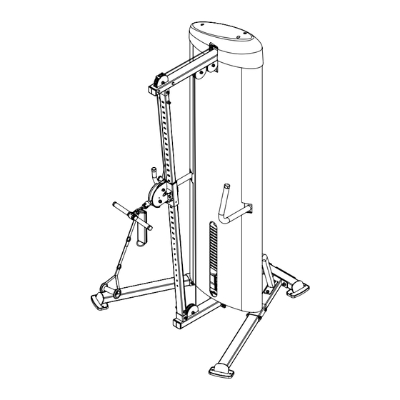
- Page 1 S2CC & A s s e m b l y I n s t r u c t i o n s O W N E R ’ S M A N U A L v. S2CC-102418...
- Page 2 before each use. Failure to do so may result in serious injury. It is imperative that you retain this Owner’s Manual and be sure all warning labels are legible and intact. Replacement Owner’s Manuals and labels are available from your local W a r n i n g , S a f e t y &...
-
Page 3: Table Of Contents
T a b l e o f C o n t e n t s • SAFETY INSTRUCTIONS......PAGE 4 • PREPARATION..........PAGE 5 • HARDWARE LIST........... PAGE 6 • HARDWARE ILLUSTRATION......PAGE 8 • PART / LIST ILLUSTRATION......PAGE 13 • ASSEMBLY INSTRUCTIONS...... -
Page 4: Safety Instructions
I m p o r t a n t S a f e t y I n s t r u c t i o n s Before beginning any fitness program, you should obtain a complete physical examination from your physician. Il est conseille de subir un examen medical complet avant d’entreprendre tout programme d’exercise. Si vous avez des etourdissements ou des faiblesses, arretez les exercices immediatement. -
Page 5: Preparation
P r e p a r a t i o n Thank you for purchasing the S2CC. This machine is part of the Body-Solid line of quality strength training machines, which lets you target specific muscle groups to achieve better muscle tone and overall body conditioning. To maximize your use of the equipment please study this Owner’s Manual thoroughly. Required Tools Assembly Tips The basic tools that you must obtain before assembling Read all “Notes” on each page before beginning each the S2CC include but are not limited to: step. While you may be able to assemble the S2CC using the m Metric Allen Key Set illustrations only, important safety notes and other tips are included in the text. m Standard Allen Key Set m Standard Wrench Set Some pieces may have extra holes that you will not use. -
Page 6: Hardware List
S 2 C C H a r d w a r e L i s t Part# Size Description Quantity M12X110mm HEX HEAD BOLT 4 PCS. M12X105mm HEX HEAD BOLT 4 PCS. M12X35mm HEX HEAD BOLT 8 PCS. M10X100mm HEX HEAD BOLT 2 PCS. - Page 7 S 2 C C H a r d w a r e L i s t Part# Size Description Quantity NYLON LOCK NUT 16 PCS. NYLON LOCK NUT 12 PCS. NYLON LOCK NUT 5 PCS. 5/16”-18 NYLON LOCK NUT 1 PCS. 1/2”...
-
Page 8: Hardware Illustration
S 2 C C H a r d w a r e I l l u s t r a t i o n PART #5 HEX HEAD BOLT M12X35 PARTIAL THRE Part #1... - Page 9 S 2 C C H a r d w a r e I l l u s t r a t i o n PART #9 ALLEN SCREW M8X8 FULL THREAD QTY.4...
- Page 10 PART #13 BUTTON HEAD CAP SCREW M8X25 FULL THREAD QTY.4 PART #13 BUTTON HEAD CAP SCREW M8X25 FULL PART #13 BUTTON HEAD CAP SCREW M8X25 FULL THREAD QTY.4 PART #13 BUTTON HEAD CAP SCREW M8X25 F S 2 C C H a r d w a r e I l l u s t r a t i o n PART #14 SOCKET HRAD CAP SCREW 3/8”-16X50.8 FULL THREAD...
- Page 11 S 2 C C H a r d w a r e I l l u s t r a t i o n Part #43 NYLON LOCK NUT 5/16”...
-
Page 12: Lock Washer
PART #53 FLAT WASHER 6.6X 12X1.6 QTY.3 PART #53 FLAT WASHER 6.6X 12X1.6 S 2 C C H a r d w a r e I l l u s t r a t i o n PART #54 FLAT WASHER 9X 16X1.6... -
Page 13: Part / List Illustration
S 2 C C P a r t s L i s t / I l l u s t r a t i o n PART F - RIGHT BRACE , 1PC. PART A - LEFT BASE FRAME, 1PC. PART G - LEFT BRACE, 1PC. - Page 14 S 2 C C P a r t s L i s t / I l l u s t r a t i o n PART K - TOP FRAME , 1PC. PART WA - WEIGHT STACK FRAME, 1PC. PART L - SWIVEL ADJUSTER, 1PC.
- Page 15 S 2 C C P a r t s L i s t / I l l u s t r a t i o n PART WE - FRONT SHROUD, 1PC. PART #60 - FOOT PAD, 4PCS. PART WF - REAR SHROUD, 1PCS. PART #61 - ADJUSTABLE LEVELER, 1PCS.
- Page 16 S 2 C C P a r t s L i s t / I l l u s t r a t i o n PART #64 - SMALL PULLEY, 4PCS. PART #68 - SNAP LINK, 1PC. PART #65 - RUBBER SLEEVE, 2PCS. PART #69 - BUSHING, 2PCS.
- Page 17 S 2 C C P a r t s L i s t / I l l u s t r a t i o n PART #72 - HANDLE END RING, 1PC. PART #76 - PLASTIC BUSHING, 2PCS. ø ø...
-
Page 18: Shaft Collar
S 2 C C P a r t s L i s t / I l l u s t r a t i o n PART #80 - HANDLE END RING, 2PCS. PART #84 - SELECTOR ROD, 1PC. ø ø... -
Page 19: Strap Handle
S 2 C C P a r t s L i s t / I l l u s t r a t i o n PART #92 - CABLE, 1PC. PART #88 - ANKLE CUFF, 1PCS. STRAP HANDLE PART #89 - , 2PCS. -
Page 20: Assembly Instructions
S T E P Be careful to assemble all components in the sequence they are presented. NOTE: Finger tighten all hardware in this step. DO NOT wrench tighten unless instructed. Some components may be pre-assembled. Nylon lock nuts will not fully screw onto bolts, they must be wrench tighten to fully go on. - Page 21 S T E P STEP Above shows Step 1 assembled and completed. 3 50 3 50...
- Page 22 S T E P Be careful to assemble all components in the sequence they are presented. NOTE: Finger tighten all hardware in this step. DO NOT wrench tighten unless instructed. Some components may be pre-assembled. Nylon lock nuts will not fully screw onto bolts, they must be wrench tighten to fully go on.
- Page 23 S T E P STEP Above shows Step 2 assembled and completed. Note: Risers (#87) are not necessary if 20pcs of weight plates are to be installed...
- Page 24 S T E P Be careful to assemble all components in the sequence they are presented. NOTE: Finger tighten all hardware in this step. DO NOT wrench tighten unless instructed. Some components may be pre-assembled. Nylon lock nuts will not fully screw onto bolts, they must be wrench tighten to fully go on.
- Page 25 S T E P STEP Above shows Step 3 assembled and completed. 64 64...
- Page 26 S T E P Be careful to assemble all components in the sequence they are presented. NOTE: Finger tighten all hardware in this step. DO NOT wrench tighten unless instructed. Some components may be pre-assembled. Nylon lock nuts will not fully screw onto bolts, they must be wrench tighten to fully go on.
- Page 27 S T E P STEP Above shows Step 4 assembled and completed.
- Page 28 S T E P Be careful to assemble all components in the sequence they are presented. NOTE: Wrench tighten ALL hardware at the end of Step 5A. Some components may be pre-assembled. Nylon lock nuts will not fully screw onto bolts, they must be wrench tighten to fully go on.
- Page 29 S T E P Above shows Step 5 assembled and completed.
- Page 30 N o t e s PCL Badge Location...
-
Page 31: Exploded View
S 2 C C E x p l o d e d V i e w... -
Page 32: Contact Page
S2CC PLEASE WRITE YOUR SERIAL NUMBER IN THE BOXES BELOW 011854-��-��-����-���� S/N # 1900 S. Des Plaines Ave. Forest Park, Il 60130 Phone:(708)427-3555 Fax:(708)427-3556 Hours: M-F 8:30 - 5:00 CST www.bodysolid.com Copyright 2009. Body-Solid. All rights reserved. Body-Solid reserves the right to change design and specifications when we feel it will improve the product. Body-Solid machines maintain several patented and patent pending features and designs.
Need help?
Do you have a question about the 2 Series and is the answer not in the manual?
Questions and answers