Table of Contents
Advertisement
Quick Links
by
A s s e m b l y
O W N E R ' S
by
VERSION 1110
&
®
Table of Contents
Dimensions. . . . . . . . . . . . . . . . . . . . . . . . . . . p. 2
Reference Drawings. . . . . . . . . . . . . . . . . . . p. 3
Important Safety Instructions. . . . . . . . . . . p. 4
Before You Begin. . . . . . . . . . . . . . . . . . . . . . p. 5
Preparations. . . . . . . . . . . . . . . . . . . . . . . . . . p. 6
®
Assembly Instructions. . . . . . . . . . . . . . . . . p. 7-13
Mainframe Parts List. . . . . . . . . . . . . . . . . . . p. 18
Hardware List. . . . . . . . . . . . . . . . . . . . . . . . . p. 19
Hardware (To Scale). . . . . . . . . . . . . . . . . . . p. 20-21
Exploded View Diagram. . . . . . . . . . . . . . . . p. 22
Notes. . . . . . . . . . . . . . . . . . . . . . . . . . . . . . . . p. 23
I n s t r u c t i o n s
M A N U A L
by
GDIB-46L
®
v. 110810
Advertisement
Table of Contents

Related Manuals for Body Solid GDIB-46L


Summary of Contents for Body Solid GDIB-46L
-
Page 1: Table Of Contents
® GDIB-46L GDIB-46L ® Table of Contents Dimensions......p. 2 Reference Drawings....p. 3 Important Safety Instructions. -
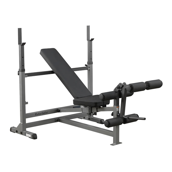
Page 2: Dimensions
The room layout diagram below will help you decide the best placement for your GDIB-46L. The dimensions of the GDIB-46L are: Width 3'10" X Length 4'8". The ceiling height requirement for the GDIB-46L is 4'4". The dimensions of the GDIB-46L are: Width 3'10" X Length 4'8". The ceiling height requirement for the GDIB-46L is 4'4". -
Page 3: Reference Drawings
R e f e r e n c e D r a w i n g s D r a w i n g s use the following diagrams to become more accustomed with your GDIB-46L and its applications. ® ®... -
Page 4: Important Safety Instructions
Such attachments might cause injuries. damaged the equipment. Wear proper exercise clothing and shoes for your Assemble and operate the GDIB-46L on a solid, level workout, no loose clothing. surface. Locate the unit a few feet from the walls or furniture to provide easy access. -
Page 5: Before You Begin
Body-Solid customer service, M-F 8:30am-5:00pm CST, at one of the following: The GDIB-46L is designed for your enjoyment. By fol- lowing these precautions and using common sense, Toll Free: (800) 556-3113 you will have many safe and pleasurable hours of... -
Page 6: Preparations
To set up this unit, you will need assistance. Do not attempt assembly by yourself. You must review and follow the instructions in this Owner’s Manual. If you do not assemble and use the GDIB-46L according to these guidelines, you could void the Body-Solid warranty. Installation Requirements CAUTION ! -
Page 7: Assembly Instructions
(in actual size) along with the corresponding component num- While you may be able to assemble the GDIB-46L us- bers in the assembly instructions. ing the illustrations only, important safety notes and other tips are included in the text. - Page 8 S T E P Be careful to assemble all components in the sequence they are presented. NOTE: Finger tighten all hardware in this step. Do Not wrench tighten until the end of Step 3. Insert both Foot Caps (14) into each Bottom Support Frame (H). Connect both Bottom Support Frame (H) to Back Cross Frame (A) using for each Bottom Support Frame (H): Two 1 (M12x75 hex head bolt)
- Page 9 S T E P S T E P S T E P Above shows STEP 1 Above shows Step 1 assembled and completed. Above shows STEP 1 assembled and completed assembled and completed...
- Page 10 S T E P Be careful to assemble all components in the sequence they are presented. NOTE: Finger tighten all hardware in this step. Do Not wrench tighten until the end of Step 3. Insert both End Caps (19) into Stabilizing Bar (G). Lay Stabilizing Bar (G) on Back Cross Frame (A) as shown.
- Page 11 S T E P S T E P S T E P Above shows STEP 2 Above shows STEP 2 Above shows Step 2 assembled and completed. assembled and completed assembled and completed...
- Page 12 Insert both Short Roller Bars (M) into Leg Frame (J). Insert both Foam Rollers (24) onto each Leg Frame (J). Insert both Nylon Washers (27) onto each Leg Frame (J). Tap both Round End Caps (26) onto each Leg Frame (J). Congratulations! The assembly of the GDIB-46L is complete.
- Page 13 S T E P S T E P S T E P Above shows STEP 3 Above shows Step 3 assembled and completed. assembled and completed Above shows STEP 3 assembled and completed...
-
Page 14: Warning, Safety & Maintenance
W a r n i n g , S a f e t y & M a i n t e n a n c e It is imperative that the user becomes familiar and understands all warnings posted on the unit. W a r n i n g , S a f e t y &... - Page 15 W a r n i n g , S a f e t y & M a i n t e n a n c e Serious injuries can be avoided with a thorough, careful and daily inspection of your equipment. Discontinue use and replace any worn parts immediately to avoid exposure to dangerous conditions.
- Page 16 W a r n i n g , S a f e t y & M a i n t e n a n c e It is imperative that the user becomes familiar and understands all warnings posted on the unit. To minimize the risk of injury, follow all safety guidelines provided with the unit and owner’s manual. CABLES: Precision craftsmanship assures Body-Solid’s ability to consistently deliver products of the highest stan-...
- Page 17 W a r n i n g , S a f e t y & M a i n t e n a n c e MAINTENANCE DAILY WEEKLY LATEST DATE ENTRY SCHEDULE ü CABLES: ü CHECK TENSION, END FITTINGS AND COATING. CHECK THAT JAM NUT ON THE SELECTOR ROD TOP BOLT IS TIGHT ü...
-
Page 18: Mainframe Parts List
M a i n f r a m e P a r t s L i s t Part# Description BACK CROSS FRAME MIDDLE FRAME SEAT CARRIAGE LIFT OFF BACK PAD FRAME SEAT PAD FRAME STABILIZING BAR 38 x 1.8T x 1048L BOTTOM SUPPORT FRAME 50 x 1.8T x 450L LEG PIVOT FRAME... -
Page 19: Hardware List
H a r d w a r e L i s t Part# Description HEX HEAD BOLT M12x75 HEX HEAD BOLT M8x45 HEX HEAD BOLT 1/2” x 85 HEX HEAD BOLT M12x70 NYLON LOCK NUT NYLON LOCK NUT 1/2” WASHER M12x34 WASHER M8x18... -
Page 20: Hardware (To Scale)
G D I B - 4 6 L H A R D W A R E H a r d w a r e ( T o S c a l e ) G D I B - 4 6 L G D I B - 4 6 L H A R D W A R E H A R D W A R E... - Page 21 H a r d w a r e ( T o S c a l e ) KEY #6 NYLON LOCK NUT 1/2" QTY.1 KEY #6 NYLON LOCK NUT 1/2" QTY.1 G D I B - 4 6 L G D I B - 4 6 L H A R D W A R E H A R D W A R E G D I B - 4 6 L...
-
Page 22: Exploded View Diagram
E x p l o d e d V i e w D i a g r a m... -
Page 23: Notes
N o t e s... - Page 24 ® 1900 S. Des Plaines Ave. Forest Park, Il 60130 (800) 556-3113 Hours: M-F 8:30 - 5:00 www.bodysolid.com Copyright 2010. Body-Solid. All rights reserved. Body-Solid reserves the right to change design and specifications when we feel it will improve the product. Body-Solid machines maintain several patented and patent pending features and designs.
Need help?
Do you have a question about the GDIB-46L and is the answer not in the manual?
Questions and answers