Advertisement
Quick Links
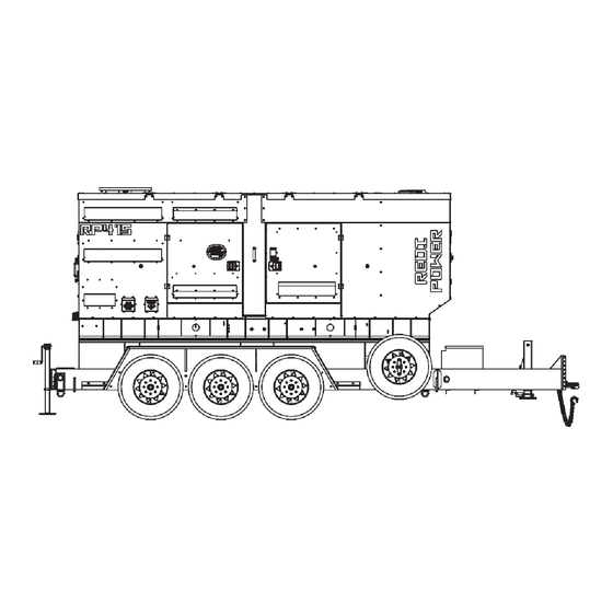
RP415F4-XX/1
INSTALLATION AND
OPERATORS MANUAL
COPY YOUR MODEL AND SERIAL NUMBER HERE
No other WINCO generator has the same serial number as
yours.
If you should ever need to contact us concerning this unit, it
will help us to respond to your needs faster.
MODEL _____________________________________________
SERIAL NUMBER _____________________________________
PURCHASE DATE ____________________________________
DEALER NAME ______________________________________
DEALER PHONE # ___________________________________
www.wincogen.com
Advertisement

Subscribe to Our Youtube Channel
Related Manuals for Winco RP415F4 /1 Series


Summary of Contents for Winco RP415F4 /1 Series
- Page 1 INSTALLATION AND OPERATORS MANUAL COPY YOUR MODEL AND SERIAL NUMBER HERE No other WINCO generator has the same serial number as yours. If you should ever need to contact us concerning this unit, it will help us to respond to your needs faster.
- Page 2 TABLE OF CONTENTS SAFETY INFORMATION WIRING DIAGRAMS SAFETY DEFINITIONS THREE PHASE AC WIRE ZIG ZAG SPECIFICATIONS THREE PHASE AC WIRE HIGH WYE DSE 7310 MKII WIRING DIAGRAM RP415 ENGINE CODES INTRODUCTION TESTING POLICY CA EMISSION CONTROL STATEMENT 35 PRODUCT DESCRIPTION REVALIDATION OF WARRANTY PREPARING THE UNIT US ENVIRONMENTAL STATEMENT...
- Page 3 Should you experience a problem please follow the “Troubleshooting Tables” near the end of this manual. The warranty listed in the manual describes what you can expect from WINCO should you need service assistance in the future. OPM-176/A...
- Page 4 SAFETY INFORMATION IMPORTANT SAFETY INSTRUCTIONS DANGER: FIRE HAZARD This engine generator set has been designed and Gasoline and other fuels present a hazard of possible manufactured to allow safe, reliable performance. Poor explosion and/or fire. maintenance, improper or careless use can result in A.
- Page 5 SPECIFICATIONS RP415 Standby Wattage 370,000 370,000 370,000 370,000 Volts 120/208 120/240 277/480 346/600 Phase Three Three Three Three Amps 1,284 1,111 Hertz Prime Wattage 333,000 333,000 333,000 333,000 Volts 120/208 120/240 277/480 346/600 Phase Three Three Three Three Amps 1,156 1,000 Hertz ENGINE...
- Page 6 Go The engine generator set consists of a multi-cylinder, liquid to the WINCO website for a list of engine dealers or contact cooled engine nominally operating at 1800 rpm. The the WINCO Service Department.
- Page 7 This must be completed and TOWING THE EQUIPMENT returned to WINCO Inc. within 180 days of the factory invoice date. CAUTION If this form is not returned, the Warranty may be voided.
- Page 8 Radiator Discharge This allows the engine-generator free movement without affecting the base or surrounding equipment. The WINCO installation manual OPM-112 contains WARNING: EQUIPMENT DAMAGE additional information on indoor, open skid installations Never mount these engine-generator sets to a wooden and is available electronically through our website or by base/structure.
- Page 9 EXHAUST INSTALLATION INSTALLING THE FUEL LINE WARNING: PERSONAL INJURY WARNING: FIRE DANGER Improper exhaust installation will allow dangerous Connecting rigid fuel line (i.e. steel or copper line) gases to seep into enclosed spaces causing a hazard to directly to the inlet fuel filter or fuel pump may cause your health and/or death.
- Page 10 A common practice is to use a solution of one pound of bicarbonate of soda (baking The WINCO solar charger consists of two parts; the solar soda) to one gallon of water. The bicarbonate of soda panel and the Sun Guard charge controller. The solar...
- Page 11 MOUNTING THE AUTOMATIC TRANSFER SWITCH For standby applications, an automatic transfer switch (ATS) will be necessary for automatic starting. A wall mounted ASCO 300 ATS designed for inside or outside installation. The transfer switch is UL1008 approved. A seven day electronic exerciser circuit is installed in the ATS as standard equipment.
- Page 12 AC CONNECTIONS C: Camlock Connections NOTICE: CLASS 1 WIRING METHODS These Cam-Locks are connected to the full load terminal ARE TO BE USED FOR ALL FIELD WIRING blocks and are capable of providing full generator output in CONNECTIONS TO TERMINALS OF A CLASS 2 all voltage configurations.
- Page 13 The NFPA 70 250:34-35 are good technical references. PERMANENTLY INSTALLED GENERATORS This WINCO portable generator ships with a bonded neutral and overcurrent protection. NFPA 70 refers to this as a “separately derived system.” When connecting it to a building a transfer switch specifically designed for GFCI and bonded neutral generators is required.
- Page 14 In order to finalize communication the program will need to be adjusted using the free DSE configuration software to enable the communication. Contact Winco service for a list of register values. The two remote start leads from the Automatic Transfer Switch are connected to the two terminals marked GROUND &...
- Page 15 DC INTERCONNECTIONS TO THE ATS WARNING Use a properly installed transfer switches when isolating the generator set from utility power. Failure to do so could result in backfeeding, which is illegal and dangerous. Backfeeding causes serious injury or DC Interconnections to the death.
- Page 16 STARTING PROCEDURE SELECTING THE CORRECT VOLTAGE (if equipped) A variety of phase voltages are available from the four position selector switch. The two basic connection patterns are Low (120/208) and High Wye (277/480) When the 277/480V 3-PH positions are selected the AVR will automatically adjust the output to the nominal voltage.
- Page 17 prior to starting. Starting this unit without it properly voltage) and padlock the lock bar to prevent the incorrect breaker from being turned on. connected can cause serious personal injury or equipment damage. WARNING: EQUIPMENT DAMAGE: DO NOT jump start these engine-generator sets. Starting Never apply a load to the generator until you have these units on a low battery or jump starting them will first checked the voltage at the terminal blocks or Cam-...
- Page 18 DEF SYSTEM NOTE: For setting the exerciser circuit, for all ATS, see the operator’s manual shipped with the ATS. This generator set is equipped with a patented HI-eSCR CONNECTING THE LOADS (selective catalyst reduction) that allows a transformation of NOx into Nitrogen (N ) and water (H 0) by injecting Urea in the exhaust pipe.
- Page 19 AVR WIRING MX321 Under normal conditions only two adjustments are made to the voltage regulator. 1 . VOLTS To adjust generator output voltage. Clockwise to increase voltage. 3. STABILITY To prevent voltage hunting. Clockwise to increase the dampening effect. OPM-176/A...
- Page 20 1. Place a drip pan or suitable container for catching the oil. WINCO has supplied a valve on the skid frame to 5. Warm up the engine by running it for 5 minutes and hook a customer supplied 5/8” hose to conveniently check for any oil leaks.
- Page 21 3. Reinstall radiator cap. 8. Tighten the drain plug to the torque indicated in the table. CHANGING COOLANT Description Torque WINCO pipes the coolant to drain to the outside for convenient maintenance. Fuel filter 32.5 ±2.5 Nm Threaded plug 1.5 ±0.5 Nm...
- Page 22 2. Refill the engine and the heat exchanger until 3. Check that there is no dirt. If there is, clean the filter complete top-off. element. Blow dry compressed air through the filter element, from the inside outward (maximum pressure 3. With the filler cap open, start the engine and keep it 200 kPa).
- Page 23 4. Connect the fuel circuit to a tank containing CFB (ISO 8. Check that the indications on the dashboard are 4113) protective fluid, and feed in the fluid by putting plausible and that there are no alarm signals. the circuit under pressure and running the engine for approximately 2 minutes, after first disabling the 9.
- Page 24 B. Old equipment requires more frequent inspection (and possibly servicing) than similar equipment that has lower hours. C. Time spent in cleaning, inspecting and correcting minor defects before they become major troubles saves time in overhaul and repair. DAILY Check Engine Oil Level Check Coolant Level and for Leakage Check Air Filter Trailer Tire Pressure...
- Page 25 TROUBLESHOOTING TABLE NOTE: Before doing any troubleshooting, check the digital display on the DSE 7310 MKII. Normally, it will tell why the unit has failed. This will shorten your troubleshooting time and in many cases, prevent the replacement of parts that may not be defective.
- Page 26 WIRING SIZE TABLE The table below is based on Table 310.16 in the National Electric Code 2020 edition. Allowable ampacitier of insulated conductrs rated 0 through 2000V, 75°C through 90°C. Not more than three current-carrying conductors in Raceway, Cable, or Earth (direct buried). Adjust for 40°C (104°F) ambient temperature.
- Page 27 WIRING DIAGRAMS THREE PHASE AC WIRE LOW WYE THREE PHASE AC WIRE HIGH WYE OPM-176/A...
- Page 28 DSE 7310 MKII WIRING DIAGRAM OPM-176/A...
- Page 29 ENGINE CODES FMI Test Translation The electrical Signal of the EGR Valve position sensor is monitored. In case of defect recognition a replacement value is 1B-3 taken. The electrical Signal of the EGR Valve position sensor is monitored. In case of defect recognition a replacement value is 1B-4 taken.
- Page 30 FMI Test Translation The Fuel Rail pressure control is executed with a device: Metering Unit (MeUn) as feeding quantity control and an 9D-12 overpressure valve allocate in the rail (PRV). Dataset Interlock Feature is used to prevent the flashing of unintended datasets on to the ECU during any SW upgrades A6-2 in field.
- Page 31 FMI Test Translation Hardware errors in the injectors and respective ECM power stages are investigated. Diagnostic procedure uses pattern detection to identify specific errors and trigger appropriate substitute reaction. The behavior pattern describes in a 28C-5 bit mask different detected problem (overcurrent, command collision, RAM error,short circuit,..) when the expected combination of errors is detected (measured and reference pattern are matching) a failure is detected.
- Page 32 FMI Test Translation Engine Starter is controlled by two relays actuators one for Low Side and one for High Side. Both power stages are 2A4-6 monitored by Hardware for electric failures. The Engine Position Management module is responsible for signals from camshaft and crankshaft sensor evaluation: angle and speed determination, signal plausibility and quality are monitored by this module.
- Page 33 FMI Test Translation The Power stage of EGR Valve actuator is monitored by Hardware for electric failures. The Power stage of electric EGR Valve actuator (H-Bridge) is monitored by Hardware for electric failures. The H-Bridge has 2 switches (High side and Low side). Each circuit is monitored separately. The Power stage of electric EGR Valve actuator (H-Bridge) is monitored by Hardware for electric failures.
- Page 34 FMI Test Translation 4009 The Power stage of Fuel Filter heater is monitored by Hardware for electric failures. FA9-5 4009 The Power stage of Fuel Filter heater is monitored by Hardware for electric failures. FA9-6 The electrical Signal of the Oxi Cat temperature upstream sensor is monitored. In case of defect recognition a substitute 4765 129D-3 value is taken.
- Page 35 CALIFORNIA EMISSION CONTROL WARRANTY STATEMENT YOUR WARRANTY RIGHTS AND OBLIGATIONS California Air Resources Board and FPT Industrial S.p.A. are pleased to explain the emission control system warranty on 2021 through 2023 off-road diesel engines. In California, new heavy-duty off-road engines must be designed, built and equipped to meet the State’s stringent anti-smog standards.
- Page 36 (12) months afterwards for a maximum of twenty-four (24) months for warranty coverage to be available, and provide written confirmation to WINCO inc that the engine was revalidated.
- Page 37 US ENVIRONMENTAL WARRANTY STATEMENT FPT Industrial S.p.A. warrants to the ultimate purchaser and each subsequent purchaser that the engine is designed, built, and equipped so as to conform with US Environmental Protection Agency (EPA) regulations applicable at the time of manufacture and that it is free from defects in workmanship or material which would cause it not to meet these regulations for a period of time: 2 years or 1,500 hours of operation, whichever occurs first, for engines less than 19kW (25HP) 5 Years or 3,000 hours of operation, whichever occurs first, for engines greater than or equal to 19kW (25 HP)
- Page 38 Air cooled units purchased for stock have 1 year to be sold. The warranty to the original retail customer commences on the date of sale of the product to them. All liquid cooled units have 180 days from the Winco invoice to submit a start up date. If no startup form is submitted, then warranty period starts on the Winco invoice date unit was sold.
- Page 39 Note 2: 3rd Year warranty coverage is parts only/no labor. Note 3: Round trip mileage is limited to 200 miles per trip and a total of 2 trips per repair unless authorized in writing by the WINCO Service Dept.
- Page 40 225 S. CORDOVA AVE • LE CENTER, MN 56057 Sales: 507-357-6821• sales@wincogen.com Service: 507-357-6831 • service@wincogen.com www.wincogen.com OPM-176/A...
Need help?
Do you have a question about the RP415F4 /1 Series and is the answer not in the manual?
Questions and answers