Table of Contents
Advertisement
Quick Links
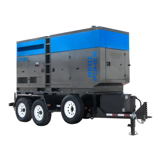
RP130F4-XX/1
INSTALLATION AND
OPERATORS MANUAL
COPY YOUR MODEL AND SERIAL NUMBER HERE
No other WINCO generator has the same serial number as
yours.
If you should ever need to contact us concerning this unit, it
will help us to respond to your needs faster.
MODEL _____________________________________________
SERIAL NUMBER _____________________________________
PURCHASE DATE ____________________________________
DEALER NAME ______________________________________
DEALER PHONE # ___________________________________
www.wincogen.com
Advertisement
Table of Contents

Related Manuals for Winco RP130


Summary of Contents for Winco RP130
- Page 1 INSTALLATION AND OPERATORS MANUAL COPY YOUR MODEL AND SERIAL NUMBER HERE No other WINCO generator has the same serial number as yours. If you should ever need to contact us concerning this unit, it will help us to respond to your needs faster.
-
Page 2: Table Of Contents
TABLE OF CONTENTS SAFETY INFORMATION WIRING SIZE TABLE SAFETY DEFINITIONS RECEPTACLE WIRING DIAGRAM SPECIFICATIONS DSE 7310 MKII WIRING DIAGRAM RP130 INTRODUCTION THREE PHASE AC WIRE LOW WYE WIRING DIAGRAMS TESTING POLICY PRODUCT DESCRIPTION THREE PHASE AC WIRE ZIG ZAG PREPARING THE UNIT... - Page 3 Should you experience a problem please follow the “Troubleshooting Tables” near the end of this manual. The warranty listed in the manual describes what you can expect from WINCO should you need service assistance in the future. REV A OPM-177...
-
Page 4: Safety Information
SAFETY INFORMATION IMPORTANT SAFETY INSTRUCTIONS DANGER: FIRE HAZARD This engine generator set has been designed and Gasoline and other fuels present a hazard of possible manufactured to allow safe, reliable performance. Poor explosion and/or fire. maintenance, improper or careless use can result in A. -
Page 5: Specifications
SPECIFICATIONS RP130 Standby Wattage 110,000 110,000 110,000 110,000 110,000 Volts 120/240 120/208 120/240 277/480 346/600 Phase Single Three Three Three Three Amps Hertz Prime Wattage 100,000 100,000 100,000 100,000 100,000 Volts 120/240 120/208 120/240 277/480 346/600 Phase Single Three Three... -
Page 6: Introduction
Go The engine generator set consists of a multi-cylinder, liquid to the WINCO website for a list of engine dealers or contact cooled engine nominally operating at 1800 rpm. The the WINCO Service Department. -
Page 7: Preparing The Unit
A Start-Up Completion & Warranty Validation Form was sent along with this manual. This must be completed and Only transport by a towing vehicle with adequate returned to WINCO Inc. within 180 days of the factory GVWR rating. invoice date. -
Page 8: Installation
Radiator Discharge This allows the engine-generator free movement without affecting the base or surrounding equipment. The WINCO installation manual OPM-112 contains WARNING: EQUIPMENT DAMAGE additional information on indoor, open skid installations Never mount these engine-generator sets to a wooden and is available electronically through our website or by base/structure. -
Page 9: Exhaust Installation
This should be your last step before initial start-up. FUEL INSTALLATION The RP130 is a 24 volt system and requires two Group 24, 12V batteries. The batteries should be rated at a minimum The fuel supply should be as close as possible to the of 650 CCA. -
Page 10: Battery Charger
A common practice is to use a solution of one pound of bicarbonate of soda (baking The WINCO solar charger consists of two parts; the solar soda) to one gallon of water. The bicarbonate of soda panel and the Sun Guard charge controller. The solar... -
Page 11: Mounting The Automatic Transfer Switch
MOUNTING THE AUTOMATIC TRANSFER SWITCH For standby applications, an automatic transfer switch (ATS) will be necessary for automatic starting. A wall mounted ASCO 300 ATS designed for inside or outside installation. The transfer switch is UL1008 approved. A seven day electronic exerciser circuit is installed in the ATS as standard equipment. -
Page 12: Ac Connections
AC CONNECTIONS C: Camlock Connections NOTICE: CLASS 1 WIRING METHODS These Cam-Locks are connected to the full load terminal ARE TO BE USED FOR ALL FIELD WIRING blocks and are capable of providing full generator output in CONNECTIONS TO TERMINALS OF A CLASS 2 all voltage configurations. -
Page 13: Voltage Selector Switch
PERMANENTLY INSTALLED GENERATORS These ground lugs are bonded to neutral and are provided for you to connect your ground wire from the transfer This WINCO portable generator ships with a bonded switch to. neutral and overcurrent protection. NFPA 70 refers to this as a “separately derived system.”... -
Page 14: Dc Connections
In order to finalize communication the program will need to be adjusted using the free DSE configuration software to enable the communication. Contact Winco service for a list of register values. The two remote start leads from the Automatic Transfer Switch are connected to the two terminals marked GROUND &... -
Page 15: Dc Interconnections To The Ats
DC INTERCONNECTIONS TO THE ATS WARNING Use a properly installed transfer switch when isolating the generator set from utility power. Failure to do so could result in backfeeding, which is illegal and DC Interconnections to the dangerous. Backfeeding cause serious injury or death. Automatic Transfer Switch WARNING *************... -
Page 16: Starting Procedure
STARTING PROCEDURE SELECTING THE CORRECT VOLTAGE (if equipped) A variety of phase voltages are available from the four position selector switch. The three basic connection patterns are Low (120/208), High Wye (277/480), and Single Phase 120/240. When the 120/240V 1-ph or the 277/480V 3-PH positions are selected the AVR will automatically adjust the output to the nominal voltage. -
Page 17: Initial Start Up
This generator is equipped with a shunt trip circuit breaker The AC output readings displayed on the DSE 7310 MKII that is interrupted by the DSE7310 controller if current limits are collected through the AC interface harness wired in are exceeded. These limits are adjusted based upon the the generator control box. -
Page 18: Connecting The Loads
DEF SYSTEM To test the Automatic Transfer Switch, follow the instruction on the operator’s manual that came with the transfer switch. If you get a fault during the initial start up or prior This generator set is equipped with a patented HI-eSCR to start up, it is most likely a false warning light. -
Page 19: Avr Wiring
AVR WIRING Installation DSE A109 This generator set has a Deep Sea digital automatic voltage 3.2 TYPICAL WIRING DIAGRAMS regulator (AVR) with CAN communication. The AVR maintains a smooth, stable regulated AC output voltage, regardless of the electrical load connected. NOTE: The DSEA109 AVR is suitable for alternators with a Permanent Magnet Generator (PMG), Auxiliary Winding or Shunt connections. -
Page 20: Maintenance
1. Place a drip pan or suitable container for catching the on new oil filter canister until sealing ring abuts the oil. WINCO has supplied a valve on the skid frame to filter head and tighten a further 3/4 turn. Do NOT use hook a customer supplied 5/8”... -
Page 21: Change Fuel Filter
CHANGING COOLANT completely free of air bubbles. Tighten the breather screw and start the engine. Let the engine run idle for a few WINCO pipes the coolant to drain to the outside for minutes to remove any residual air. convenient maintenance. -
Page 22: Cleaning Radiator
cooling liquid air bleed. second locking handle; during this operation, take care to ensure that no dust gets into the sleeve. 4. Stop the engine and top up again. 3. Check that there is no dirt. If there is, clean the filter 5. -
Page 23: Storage
3. DEF back-flow to tank 8. Attach signs reading “ENGINE WITHOUT OIL” to the engine and to the on-board control panel. 4. DEF outlet to Dosing Module 9. Drain the coolant, if it has not been mixed with suitable 5. Pressure sensor antifreeze and corrosion inhibitors, and affix a sign to indicate the fact. -
Page 24: Maintenance Schedule
MAINTENANCE SCHEDULE DAILY The ultimate aim of a preventive maintenance program Check Engine Oil Level is to maintain the equipment in optimum condition, for Check Coolant Level and for Leakage the maximum amount of time during it’s useful life. The detection of faults before they develop into major problems Check Air Restriction Indicator will decrease downtime. -
Page 25: Troubleshooting Table
TROUBLESHOOTING TABLE NOTE: Before doing any trouble shooting, check the digital display on the DSE 7310 MKII. Normally, it will tell why the unit has failed. This will shorten your trouble shooting time and in many cases, prevent the replacement of parts that may not be defective. -
Page 26: Wiring Size Table
WIRING SIZE TABLE The table below is based on Table 310.16 in the National Electric Code 2020 edition. Allowable ampacitier of insulated conductrs rated 0 through 2000V, 75°C through 90°C. Not more than three current-carrying conductors in Raceway, Cable, or Earth (direct buried). Adjust for 40°C (104°F) ambient temperature. -
Page 27: Receptacle Wiring Diagram
RECEPTACLE WIRING DIAGRAM (if equipped) REV A OPM-177... -
Page 28: Dse 7310 Mkii Wiring Diagram
DSE 7310 MKII WIRING DIAGRAM OPM-177 REV A... -
Page 29: Three Phase Ac Wire Low Wye
WIRING DIAGRAMS SINGLE PHASE ZIG ZAG THREE PHASE AC WIRE LOW WYE THREE PHASE AC WIRE HIGH WYE REV A OPM-177... -
Page 30: Dc Harness Schematic
DC HARNESS SCHEMATIC OPM-177 REV A... -
Page 31: Engine Harness
ENGINE HARNESS REV A OPM-177... -
Page 32: Engine Codes
ENGINE CODES FMI Test Translation The electrical Signal of the EGR Valve position sensor is monitored. In case of defect recognition a replacement value is 1B-3 taken. The electrical Signal of the EGR Valve position sensor is monitored. In case of defect recognition a replacement value is 1B-4 taken. - Page 33 FMI Test Translation The Fuel Rail pressure control is executed with a device: Metering Unit (MeUn) as feeding quantity control and an 9D-12 overpressure valve allocate in the rail (PRV). Dataset Interlock Feature is used to prevent the flashing of unintended datasets on to the ECU during any SW upgrades A6-2 in field.
- Page 34 FMI Test Translation Hardware errors in the injectors and respective ECM power stages are investigated. Diagnostic procedure uses pattern detection to identify specific errors and trigger appropriate substitute reaction. The behavior pattern describes in a 28C-5 bit mask different detected problem (overcurrent, command collision, RAM error,short circuit,..) when the expected combination of errors is detected (measured and reference pattern are matching) a failure is detected.
- Page 35 FMI Test Translation Engine Starter is controlled by two relays actuators one for Low Side and one for High Side. Both power stages are 2A4-6 monitored by Hardware for electric failures. The Engine Position Management module is responsible for signals from camshaft and crankshaft sensor evaluation: angle and speed determination, signal plausibility and quality are monitored by this module.
- Page 36 FMI Test Translation The Power stage of EGR Valve actuator is monitored by Hardware for electric failures. The Power stage of electric EGR Valve actuator (H-Bridge) is monitored by Hardware for electric failures. The H-Bridge has 2 switches (High side and Low side). Each circuit is monitored separately. The Power stage of electric EGR Valve actuator (H-Bridge) is monitored by Hardware for electric failures.
- Page 37 FMI Test Translation 4009 The Power stage of Fuel Filter heater is monitored by Hardware for electric failures. FA9-5 4009 The Power stage of Fuel Filter heater is monitored by Hardware for electric failures. FA9-6 The electrical Signal of the Oxi Cat temperature upstream sensor is monitored. In case of defect recognition a substitute 4765 129D-3 value is taken.
- Page 38 CALIFORNIA EMISSION CONTROL WARRANTY STATEMENT YOUR WARRANTY RIGHTS AND OBLIGATIONS California Air Resources Board and FPT Industrial S.p.A. are pleased to explain the emission control system warranty on 2021 through 2023 off-road diesel engines. In California, new heavy-duty off-road engines must be designed, built and equipped to meet the State’s stringent anti-smog standards.
- Page 39 CALIFORNIA EMISSION CONTROL WARRANTY PARTS LIST Fuel injection system Positive Crankcase Ventilation (PCA)system (if applicable) • Fuel injection part • PCV valve • Fuel injectors • Oil cap filler • Fuel injection lines Exhaust Gas Recirculation Systems (EGR) Exhaust after treatment devices (if applicable) •...
-
Page 40: Environmental Statement
US ENVIRONMENTAL WARRANTY STATEMENT FPT Industrial S.p.A. warrants to the ultimate purchaser and each subsequent purchaser that the engine is designed, built, and equipped so as to conform with US Environmental Protection Agency (EPA) regulations applicable at the time of manufacture and that it is free from defects in workmanship or material which would cause it not to meet these regulations for a period of time: 2 years or 1,500 hours of operation, whichever occurs first, for engines less than 19kW (25HP) 5 Years or 3,000 hours of operation, whichever occurs first, for engines greater than or equal to 19kW (25 HP) -
Page 41: Revalidation Of Warranty
(12) months afterwards for a maximum of twenty-four (24) months for warranty coverage to be available, and provide written confirmation to WINCO inc that the engine was revalidated. -
Page 42: Warranty Statement
Air cooled units purchased for stock have 1 year to be sold. The warranty to the original retail customer commences on the date of sale of the product to them. All liquid cooled units have 180 days from the Winco invoice to submit a start up date. - Page 43 Standby use is defined as an application where utility power is present -and- the generator set is used as emergency backup during utility power outages. WINCO reserves the right to change or improve it’s products without incurring any obligations to make such changes or improvements on products purchased previously.
- Page 44 225 S. CORDOVA AVE • LE CENTER, MN 56057 Sales: 507-357-6821• sales@wincogen.com Service: 507-357-6831 • service@wincogen.com www.wincogen.com OPM-177 REV A...
Need help?
Do you have a question about the RP130 and is the answer not in the manual?
Questions and answers