Table of Contents
Advertisement
Quick Links
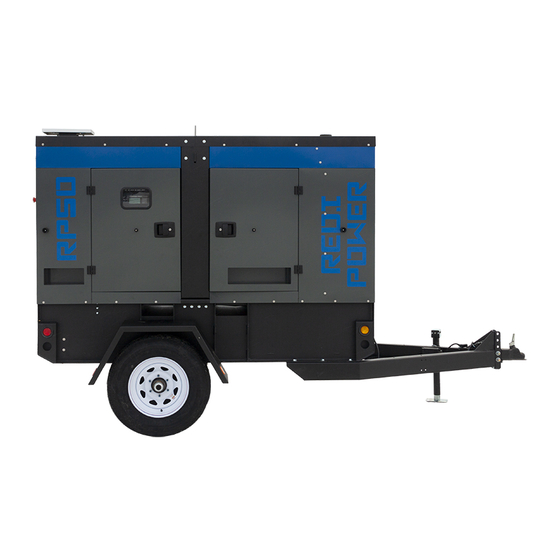
RP50
INSTALLATION & OPERATORS
MANUAL
COPY YOUR MODEL AND SERIAL NUMBER HERE
No other WINCO generator has the same serial number as yours.
If you should ever need to contact us concerning this unit, it will
help us to respond to your needs faster.
MODEL __________________________________________________
16200-021
SERIAL NUMBER _________________________________________
PURCHASE DATE _________________________________________
DEALER NAME ___________________________________________
DEALER PHONE # ________________________________________
www.wincogen.com
Advertisement
Table of Contents

Subscribe to Our Youtube Channel
Related Manuals for Winco RP50


Summary of Contents for Winco RP50
- Page 1 MANUAL COPY YOUR MODEL AND SERIAL NUMBER HERE No other WINCO generator has the same serial number as yours. If you should ever need to contact us concerning this unit, it will help us to respond to your needs faster.
-
Page 2: Table Of Contents
Should you experience a problem please follow the MAINTENANCE SCHEDULE “Troubleshooting Tables” near the end of this manual. The warranty listed in the manual describes what you can expect from WINCO should you need service assistance in the future. OPM-148 REV A... -
Page 3: Safety Information
SAFETY INFORMATION C. Do not smoke or use open flame near the generator This engine generator set has been designed and set or fuel tank. manufactured to allow safe, reliable performance. Poor D. Keep a fire extinguisher nearby and know its proper maintenance, improper or careless use can result in use. -
Page 4: Specifications
SPECIFICATIONS RP50 Standby Wattage 47,500 47,500 47,500 47,500 47,500 47,500 59,375 59,375 59,375 59,375 Volts 120/240 120/208 120/240 277/480 346/600 Phase Single Three Three Three Three Amps Hertz Prime Wattage 42,750 42,750 42,750 42,750 42,750 42,750 53,438 53,438 53,438 53,438... -
Page 5: Introduction
Go cooled engine nominally operating at 1800 rpm. The to the WINCO website for a list of engine dealers or contact generator frequency regulation is maintained by the engine the WINCO Service Department. -
Page 6: Preparing The Unit
A Start-Up Completion & Warranty Validation Form was sent along with this manual. This must be completed and Only transport by a towing vehicle with adequate returned to WINCO Inc. within 180 days of the factory GVWR rating. invoice date. -
Page 7: Installation
Radiator Discharge This allows the engine-generator free movement without affecting the base or surrounding equipment. The WINCO installation manual OPM-112 contains WARNING: EQUIPMENT DAMAGE additional information on indoor, open skid installations Never mount these engine-generator sets to a wooden and is available electronically through our website or by base/structure. -
Page 8: Exhaust Installation
This should be your last step before initial start-up. FUEL INSTALLATION The RP50 is a 12 volt system and requires a single battery. The batteries should be rated at a minimum of 650 CCA. The fuel supply should be as close as possible to the Installation of the highest CCA rated battery, within the engine. -
Page 9: Battery Charger
require various types of maintenance. Refer to the battery CAUTION: PERSONAL DANGER manufacturer for specific recommendations. NEVER dispose a battery in a fire. The battery is capable of exploding. NOTE: Always make sure that a new battery is fully charged DO NOT open or mutilate the battery. -
Page 10: Optional Solar Charger
Total running load must not exceed generator rating. OPTIONAL SOLAR CHARGER The WINCO solar option consists of two parts; the solar panel and the Sun Guard charge controller. The solar panel collects the energy while the Sun Guard controls the charging process acting as a switch to prevent the solar panel from discharging or overcharging the battery. -
Page 11: Ac Connections
AC CONNECTIONS E: Camlock Connections NOTICE: CLASS 1 WIRING METHODS These Cam-Locks are connected to the full load terminal ARE TO BE USED FOR ALL FIELD WIRING blocks and are capable of providing full generator output in CONNECTIONS TO TERMINALS OF A CLASS 2 all voltage configurations. -
Page 12: Voltage Selector Switch
PERMANENTLY INSTALLED GENERATORS GROUND LUG: These ground lugs are bonded to neutral and are provided This WINCO portable generator ships with a bonded for you to connect your ground wire from the transfer neutral and overcurrent protection. NFPA 70 refers to this switch to. -
Page 13: Dc Connections
In order to finalize communication the program will need to be adjusted using the free DSE configuration software to enable the commutation. Contact Winco service for a list of register values. The two remote start leads from the Automatic Transfer Switch are connected to the two terminals marked GROUND &... -
Page 14: Dc Interconnections To The Ats
DC INTERCONNECTIONS TO THE ATS WARNING Use a properly installed transfer switches when isolating the generator set from utility power. Failure to do so could result in backfeeding, which is illegal and dangerous. Backfeeding cause serious injury or DC Interconnections to the death. -
Page 15: Starting Procedure
STARTING PROCEDURE SELECTING THE CORRECT VOLTAGE (if equipped) A variety of phase voltages are available from the four position selector switch. The three basic connection patterns are Low (120/208), High Wye (277/480), and Single Phase 120/240. When the 120/240V 1-ph or the 277/480V 3-PH positions are selected the AVR will automatically adjust the output to the nominal voltage. -
Page 16: Initial Start Up
This generator is equipped with a shunt trip circuit breaker The AC ouptut readings displayed on the DSE 7310 MKII that is interrupted by the DSE7310 controller if current limits are collected through the AC interface harness wired in are exceeded. These limites are adjusted based upon the the generator control box. -
Page 17: Connecting The Loads
To test the Automatic Transfer Switch, follow the instruction on the operator’s manual that came with the transfer switch. If you get a fault during the initial start up or prior to start up, it is most likely a false warning light. Simply reset the ATS start over. -
Page 18: Avr Wiring
AVR WIRING Installation DSE A109 3.2 TYPICAL WIRING DIAGRAMS This generator set has a Deep Sea digital automatic voltage regulator (AVR) with CAN communication. The AVR maintains a smooth, stable regulated AC output voltage, regardless of the electrical load connected. NOTE: The DSEA109 AVR is suitable for alternators with a Permanent Magnet Generator (PMG), Auxiliary Winding or Shunt connections. -
Page 19: Maintenance
1. Place a drip pan or suitable container for catching the on new oil filter canister until sealing ring abuts the oil. WINCO has supplied a valve on the skid frame to filter head and tighten a further 3/4 turn. Do NOT use hook a customer supplied 5/8”... -
Page 20: Change Fuel Filter
CHANGE FUEL FILTER CHANGING COOLANT WARNING WINCO pipes the coolant to drain to the outside for convenient maintenance. Do not fill up the new filter before it is fitted to the support, to avoid inserting harmful impurities into the Engine coolant contaminated with rust or water scale injection system and circuit. -
Page 21: Replacing Blow-By Filter
CHANGING AIR FILTER REPLACING BLOW-BY FILTER The engine performance is adversely affected when WARNING the air cleaner element is clogged with dust. Do NOT perform while the engine is running. WARNING: EQUIPMENT DAMAGE Using Illustration 1: Never operate the engine with the air cleaner element removed. -
Page 22: Storage
Using Illustration 3: INFINITE PERIOD In order to prevent oxidation of the internal parts of the engine and of certain components in the injection system, when the engine is expected to be inoperative for periods of more than two months, the following operations must be carried out in preparation for this: 1. -
Page 23: Maintenance Schedule
MAINTENANCE SCHEDULE The ultimate aim of a preventive maintenance program is to maintain the equipment in optimum condition, for the maximum amount of time during it’s useful life. The detection of faults before they develop into major problems will decrease downtime. A regular schedule of cleaning and inspection will help assure trouble-free operation. -
Page 24: Troubleshooting Table
TROUBLESHOOTING TABLE NOTE: Before doing any trouble shooting, check the digital display on the DSE 7310 MKII. Normally, it will tell why the unit has failed. This will shorten your trouble shooting time and in many cases, prevent the replacement of parts that may not be defective. -
Page 25: Wiring Size Table
WIRING SIZE TABLE The table below is based on Table 310.15 (B) (16) in the National Electric Code 2014 edition. Allowable ampacitier of insulated conductors rated 0 through 2000V, 75°C through 90°C. Not more than three current-carrying conductors in Raceway, Cable, or Earth (direct buried). Adjust for 40°C (104°F) ambient temperature. -
Page 26: Selector Switch Wiring Diagram
SELECTOR SWITCH WIRING DIAGRAM (if equipped) SEE FOLLOWING PAGE FOR REFERENCES OPM-148 REV A... - Page 27 REV A OPM-148...
-
Page 28: Dse 7310 Mkii Wiring Diagram
DSE 7310 MKII WIRING DIAGRAM OPM-148 REV A... -
Page 29: Three Phase Ac Wire High Wye
WIRING DIAGRAMS THREE PHASE WIRING - DELTA THREE PHASE AC WIRE HIGH WYE SINGLE PHASE AC WIRING - 4 LEAD THREE PHASE AC WIRE LOW WYE REV A OPM-148... -
Page 30: Engine Harness
ENGINE HARNESS OPM-148 REV A... -
Page 31: Engine Codes
ENGINE CODES FMI Test Translation The electrical Signal of the EGR Valve position sensor is monitored. In case of defect recognition a replacement value is 1B-3 taken. The electrical Signal of the EGR Valve position sensor is monitored. In case of defect recognition a replacement value is 1B-4 taken. - Page 32 FMI Test Translation The Fuel Rail pressure control is executed with a device: Metering Unit (MeUn) as feeding quantity control and an 9D-12 overpressure valve allocate in the rail (PRV). Dataset Interlock Feature is used to prevent the flashing of unintended datasets on to the ECU during any SW upgrades A6-2 in field.
- Page 33 FMI Test Translation Hardware errors in the injectors and respective ECM power stages are investigated. Diagnostic procedure uses pattern detection to identify specific errors and trigger appropriate substitute reaction. The behavior pattern describes in a 28C-5 bit mask different detected problem (overcurrent, command collision, RAM error,short circuit,..) when the expected combination of errors is detected (measured and reference pattern are matching) a failure is detected.
- Page 34 FMI Test Translation Engine Starter is controlled by two relays actuators one for Low Side and one for High Side. Both power stages are 2A4-6 monitored by Hardware for electric failures. The Engine Position Management module is responsible for signals from camshaft and crankshaft sensor evaluation: angle and speed determination, signal plausibility and quality are monitored by this module.
- Page 35 FMI Test Translation The Power stage of EGR Valve actuator is monitored by Hardware for electric failures. The Power stage of electric EGR Valve actuator (H-Bridge) is monitored by Hardware for electric failures. The H-Bridge has 2 switches (High side and Low side). Each circuit is monitored separately. The Power stage of electric EGR Valve actuator (H-Bridge) is monitored by Hardware for electric failures.
- Page 36 FMI Test Translation 4009 The Power stage of Fuel Filter heater is monitored by Hardware for electric failures. FA9-5 4009 The Power stage of Fuel Filter heater is monitored by Hardware for electric failures. FA9-6 The electrical Signal of the Oxi Cat temperature upstream sensor is monitored. In case of defect recognition a substitute 4765 129D-3 value is taken.
-
Page 37: Ca Emission Statement
CALIFORNIA EMISSION CONTROL WARRANTY STATEMENT YOUR WARRANTY RIGHTS AND OBLIGATIONS California Air Recourses Board and FPT Industrial S.p.A. are pleased to explain the emission control system warranty on 2018 to 2020 off-road engines. In California, new heavy-duty off-road engines must be designed, built, and equipped to meet the state’s stringent anti-smog standards. - Page 38 US ENVIRONMENTAL WARRANTY STATEMENT FPT Industrial S.p.A. warrants to the ultimate purchaser and each subsequent purchaser that the engine is designed, built, and equipped so as to conform with US Environmental Protection Agency (EPA) regulations applicable at the time of manufacture and that it is free from defects in workmanship or material which would cause it not to meet these regulations for a period of time: 2 years or 1,500 hours of operation, whichever occurs first, for engines less than 19kW (25HP) 5 Years or 3,000 hours of operation, whichever occurs first, for engines greater than or equal to 19kW (25 HP)
-
Page 39: Revalidation Of Warranty
(12) months afterwards for a maximum of twenty-four (24) months for warranty coverage to be available, and provide written confirmation to WINCO inc that the engine was revalidated. -
Page 40: Month Limited Warranty
Warranty service may be performed by an authorized WINCO Inc. service center only. Service work performed by unauthorized persons will void all warranties. WINCO Inc. shall not be liable for any claim in an amount greater than the purchase price of the product. In no event shall WINCO Inc. be held liable for any special, indirect, consequential or liquidated damages.
Need help?
Do you have a question about the RP50 and is the answer not in the manual?
Questions and answers