
Subscribe to Our Youtube Channel
Related Manuals for Winco RP210


Summary of Contents for Winco RP210
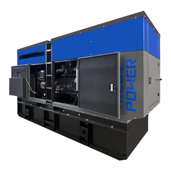
- Page 1 RP210F4-XX/1 GENERATORS AN AMERICAN COMPANY INSTALLATION AND OPERATORS MANUAL www.wincogen.com...
-
Page 2: Table Of Contents
TROUBLESHOOTING TABLE SAFETY INFORMATION WIRING SIZE TABLE ANSI SAFETY DEFINITIONS CIRCUIT WIRING DIAGRAM SPECIFICATIONS RECEPTACLE WIRING DIAGRAM RP210 INTRODUCTION SHORE POWER WIRING DIAGRAM TESTING POLICY DSE 7310 MKII WIRING DIAGRAM PRODUCT DESCRIPTION THREE PHASE AC WIRE LOW WYE PREPARING THE UNIT... - Page 3 WINCO should you need service assistance in the future. COPY YOUR MODEL AND SERIAL NUMBER HERE No other WINCO generator has the same serial number as yours. If you should ever need to contact us concerning this unit, it will help us to respond to your needs faster.
-
Page 4: Safety Information
SAFETY INFORMATION C. Do not smoke or use open flame near the generator This engine generator set has been designed and set or fuel tank. manufactured to allow safe, reliable performance. Poor D. Keep a fire extinguisher nearby and know its proper maintenance, improper or careless use can result in use. -
Page 5: Specifications
SPECIFICATIONS RP210 Standby Wattage 180,000 180,000 180,000 Volts 120/240 120/240 277/480 Phase Single Three Three Amps Hertz Prime Wattage 162,000 162,000 162,000 Volts 120/240 120/240 277/480 Phase Single Three Three Amps Hertz ENGINE Make Model Displacement 6.7L Governor Electric ENGINE FLUID SPECIFICATIONS... -
Page 6: Introduction
Go The engine generator set consists of a multi-cylinder, liquid to the WINCO website for a list of engine dealers or contact cooled engine nominally operating at 1800 rpm. The the WINCO Service Department. -
Page 7: Preparing The Unit
A Start-Up Completion & Warranty Validation Form was sent along with this manual. This must be completed and Only transport by a towing vehicle with adequate returned to WINCO Inc. within 180 days of the factory GVWR rating. invoice date. -
Page 8: Installation
Radiator Discharge This allows the engine-generator free movement without affecting the base or surrounding equipment. The WINCO installation manual OPM-112 contains WARNING: EQUIPMENT DAMAGE additional information on indoor, open skid installations Never mount these engine-generator sets to a wooden and is available electronically through our website or by base/structure. -
Page 9: Exhaust Installation
This should be your last step before initial start-up. FUEL INSTALLATION The RP210 is a 24 volt system and requires two 12V batteries. The batteries should be rated at a minimum of The fuel supply should be as close as possible to the 650 CCA. -
Page 10: Battery Charger
require various types of maintenance. Refer to the battery CAUTION: PERSONAL DANGER manufacturer for specific recommendations. NEVER dispose a battery in a fire. The battery is capable of exploding. NOTE: Always make sure that a new battery is fully charged DO NOT open or mutilate the battery. -
Page 11: Optional Solar Charger
Total running load must not exceed generator rating. OPTIONAL SOLAR CHARGER The WINCO solar option consists of two parts; the solar panel and the Sun Guard charge controller. The solar panel collects the energy while the Sun Guard controls the charging process acting as a switch to prevent the solar panel from discharging or overcharging the battery. -
Page 12: Ac Connections
AC CONNECTIONS C: Camlock Connections NOTICE: CLASS 1 WIRING METHODS These Cam-Locks are connected to the full load terminal ARE TO BE USED FOR ALL FIELD WIRING blocks and are capable of providing full generator output in CONNECTIONS TO TERMINALS OF A CLASS 2 all voltage configurations. -
Page 13: Voltage Selector Switch
PERMANENTLY INSTALLED GENERATORS for you to connect your ground wire from the transfer switch to. This WINCO portable generator ships with a bonded neutral and overcurrent protection. NFPA 70 refers to this L1, L2, & L3 POWER OUTPUT LUGS: as a “separately derived system.” When connecting it to a... -
Page 14: Dc Connections
In order to finalize communication the program will need to be adjusted using the free DSE configuration software to enable the commutation. Contact Winco service for a list of register values. The two remote start leads from the Automatic Transfer Switch are connected to the two terminals marked GROUND &... -
Page 15: Dc Interconnections To The Ats
DC INTERCONNECTIONS TO THE ATS WARNING Use a properly installed transfer switches when isolating the generator set from utility power. Failure to do so could result in backfeeding, which is illegal and dangerous. Backfeeding cause serious injury or DC Interconnections to the death. -
Page 16: Starting Procedure
STARTING PROCEDURE SELECTING THE CORRECT VOLTAGE (if equipped) A variety of phase voltages are available from the four position selector switch. The three basic connection patterns are Low (120/208), High Wye (277/480), and Single Phase 120/240. When the 120/240V 1-ph or the 277/480V 3-PH positions are selected the AVR will automatically adjust the output to the nominal voltage. -
Page 17: Initial Start Up
This generator is equipped with a shunt trip circuit breaker The AC ouptut readings displayed on the DSE 7310 MKII that is interrupted by the DSE7310 controller if current limits are collected through the AC interface harness wired in are exceeded. These limites are adjusted based upon the the generator control box. -
Page 18: Connecting The Loads
DEF SYSTEM To test the Automatic Transfer Switch, follow the instruction on the operator’s manual that came with the transfer switch. If you get a fault during the initial start up or prior This generator set is equipped with a patented HI-eSCR to start up, it is most likely a false warning light. -
Page 19: Avr Wiring
AVR WIRING Installation DSE A109 This generator set has a Deep Sea digital automatic voltage 3.2 TYPICAL WIRING DIAGRAMS regulator (AVR) with CAN communication. The AVR maintains a smooth, stable regulated AC output voltage, regardless of the electrical load connected. NOTE: The DSEA109 AVR is suitable for alternators with a Permanent Magnet Generator (PMG), Auxiliary Winding or Shunt connections. -
Page 20: Maintenance
1. Place a drip pan or suitable container for catching the on new oil filter canister until sealing ring abuts the oil. WINCO has supplied a valve on the skid frame to filter head and tighten a further 3/4 turn. Do NOT use hook a customer supplied 5/8”... -
Page 21: Change Fuel Filter
3/4 CHANGING COOLANT of a turn. WINCO pipes the coolant to drain to the outside for After replacing the fuel filter, there may be oil bubbles convenient maintenance. in the fuel circuit. Bleed the residual air from the filter... -
Page 22: Cleaning Radiator
5. Dispose of coolant in accordance to local codes. DO 3. Check that there is no dirt. If there is, clean the filter NOT dispose or allow oil to seep into the ground or element. Blow dry compressed air through the filter sewer systems, doing so will cause environmental element, from the inside outward (maximum pressure damage. -
Page 23: Def System
INFINITE PERIOD 3. Drain the CFB protective fluid from the fuel circuit. 4. Remove the plugs and/or seals from the engine’s In order to prevent oxidation of the internal parts of the intake, discharge, ventilation and bleeder holes, engine and of certain components in the injection system, restoring normal conditions of use. -
Page 24: Maintenance Schedule
DAILY Check Engine Oil Level Check Coolant Level and for Leakage Check Air Filter Trailer tire pressure MONTHLY Tighten trailer lug nuts EVERY 6 MONTHS Check Electrolyte Level in Battery and Clean Terminals Check Exhaust System for Damage Clean Fuel Tank 1. -
Page 25: Troubleshooting Table
TROUBLESHOOTING TABLE NOTE: Before doing any trouble shooting, check the digital display on the DSE 7310 MKII. Normally, it will tell why the unit has failed. This will shorten your trouble shooting time and in many cases, prevent the replacement of parts that may not be defective. -
Page 26: Wiring Size Table
WIRING SIZE TABLE The table below is based on Table 310.15 (B) (16) in the National Electric Code 2014 edition. Allowable ampacitier of insulated conductors rated 0 through 2000V, 75°C through 90°C. Not more than three current-carrying conductors in Raceway, Cable, or Earth (direct buried). Adjust for 40°C (104°F) ambient temperature. - Page 27 Page Left Intentionally Blank REV A OPM-169...
-
Page 28: Circuit Wiring Diagram
CIRCUIT WIRING DIAGRAM (if equipped) OPM-169 REV A... -
Page 29: Receptacle Wiring Diagram
RECEPTACLE WIRING DIAGRAM (if equipped) REV A OPM-169... -
Page 30: Shore Power Wiring Diagram
SHORE POWER WIRING DIAGRAM (if equipped) OPM-169 REV A... -
Page 31: Dse 7310 Mkii Wiring Diagram
DSE 7310 MKII WIRING DIAGRAM REV A OPM-169... -
Page 32: Three Phase Ac Wire Low Wye
WIRING DIAGRAMS THREE PHASE AC WIRE LOW WYE THREE PHASE AC WIRE HIGH WYE THREE PHASE AC WIRE ZIG ZAG OPM-169 REV A... -
Page 33: Dc Harness Schematic
DC HARNESS SCHEMATIC REV A OPM-169... -
Page 34: Engine Harness
ENGINE HARNESS OPM-169 REV A... -
Page 35: Engine Codes
ENGINE CODES FMI Test Translation The electrical Signal of the EGR Valve position sensor is monitored. In case of defect recognition a replacement value is 1B-3 taken. The electrical Signal of the EGR Valve position sensor is monitored. In case of defect recognition a replacement value is 1B-4 taken. - Page 36 FMI Test Translation The Fuel Rail pressure control is executed with a device: Metering Unit (MeUn) as feeding quantity control and an 9D-12 overpressure valve allocate in the rail (PRV). Dataset Interlock Feature is used to prevent the flashing of unintended datasets on to the ECU during any SW upgrades A6-2 in field.
- Page 37 FMI Test Translation Hardware errors in the injectors and respective ECM power stages are investigated. Diagnostic procedure uses pattern detection to identify specific errors and trigger appropriate substitute reaction. The behavior pattern describes in a 28C-5 bit mask different detected problem (overcurrent, command collision, RAM error,short circuit,..) when the expected combination of errors is detected (measured and reference pattern are matching) a failure is detected.
- Page 38 FMI Test Translation Engine Starter is controlled by two relays actuators one for Low Side and one for High Side. Both power stages are 2A4-6 monitored by Hardware for electric failures. The Engine Position Management module is responsible for signals from camshaft and crankshaft sensor evaluation: angle and speed determination, signal plausibility and quality are monitored by this module.
- Page 39 FMI Test Translation The Power stage of EGR Valve actuator is monitored by Hardware for electric failures. The Power stage of electric EGR Valve actuator (H-Bridge) is monitored by Hardware for electric failures. The H-Bridge has 2 switches (High side and Low side). Each circuit is monitored separately. The Power stage of electric EGR Valve actuator (H-Bridge) is monitored by Hardware for electric failures.
- Page 40 FMI Test Translation 4009 The Power stage of Fuel Filter heater is monitored by Hardware for electric failures. FA9-5 4009 The Power stage of Fuel Filter heater is monitored by Hardware for electric failures. FA9-6 The electrical Signal of the Oxi Cat temperature upstream sensor is monitored. In case of defect recognition a substitute 4765 129D-3 value is taken.
-
Page 41: California Emission Control
CALIFORNIA EMISSION CONTROL WARRANTY STATEMENT YOUR WARRANTY RIGHTS AND OBLIGATIONS California Air Resources Board and FPT Industrial S.p.A. are pleased to explain the emission control system warranty on 2021 through 2023 off-road diesel engines. In California, new heavy-duty off-road engines must be designed, built and equipped to meet the State’s stringent anti-smog standards. - Page 42 CALIFORNIA EMISSION CONTROL WARRANTY PARTS LIST Fuel injection system Positive Crankcase Ventilation (PCA)system (if applicable) • Fuel injection part • PCV valve • Fuel injectors • Oil cap filler • Fuel injection lines Exhaust Gas Recirculation Systems (EGR) Exhaust after treatment devices (if applicable) •...
-
Page 43: Environmental Warranty
US ENVIRONMENTAL WARRANTY STATEMENT FPT Industrial S.p.A. warrants to the ultimate purchaser and each subsequent purchaser that the engine is designed, built, and equipped so as to conform with US Environmental Protection Agency (EPA) regulations applicable at the time of manufacture and that it is free from defects in workmanship or material which would cause it not to meet these regulations for a period of time: 2 years or 1,500 hours of operation, whichever occurs first, for engines less than 19kW (25HP) 5 Years or 3,000 hours of operation, whichever occurs first, for engines greater than or equal to 19kW (25 HP) -
Page 44: Revalidation Of Warranty
(12) months afterwards for a maximum of twenty-four (24) months for warranty coverage to be available, and provide written confirmation to WINCO inc that the engine was revalidated. -
Page 45: Warranty Statement
Air cooled units purchased for stock have 1 year to be sold. The warranty to the original retail customer commences on the date of sale of the product to them. All liquid cooled units have 180 days from the Winco invoice to submit a start up date. - Page 46 Standby use is defined as an application where utility power is present -and- the generator set is used as emergency backup during utility power outages. WINCO reserves the right to change or improve it’s products without incurring any obligations to make such changes or improvements on products purchased previously.
- Page 47 22. Travel time or service calls unless specifically authorized by Winco, Inc. in writing. GENERAL INFORMATION The WINCO, Inc. Service Department is open from 7:30 AM to 4:30 PM Central Standard time. It is located at 225 South Cordova Ave., Le Center, MN, 56057-1805. Phone Numbers: Service Department - 507-357-6831 FAX Line - 507-357-4857.
- Page 48 GENERATORS AN AMERICAN COMPANY 225 S. CORDOVA AVE • LE CENTER, MN 56057 Sales: 507-357-6821• sales@wincogen.com Service: 507-357-6831 • service@wincogen.com www.wincogen.com OPM-169 REV A...
Need help?
Do you have a question about the RP210 and is the answer not in the manual?
Questions and answers