Table of Contents
Advertisement
Quick Links
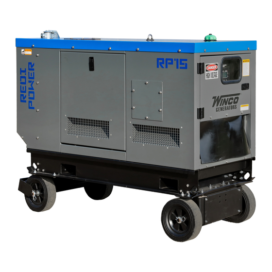
RP15Y2
INSTALLATION & OPERATORS
MANUAL
COPY YOUR MODEL AND SERIAL NUMBER HERE
No other WINCO generator has the same serial number as yours.
If you should ever need to contact us on this unit, it will help us to
respond to your needs faster.
MODEL __________________________________________________
16200-041
SERIAL NUMBER _________________________________________
PURCHASE DATE _________________________________________
DEALER NAME ___________________________________________
DEALER PHONE # ________________________________________
www.wincogen.com
Advertisement
Table of Contents

Related Manuals for Winco RP15


Summary of Contents for Winco RP15
- Page 1 MANUAL COPY YOUR MODEL AND SERIAL NUMBER HERE No other WINCO generator has the same serial number as yours. If you should ever need to contact us on this unit, it will help us to respond to your needs faster.
-
Page 2: Table Of Contents
TABLE OF CONTENTS SAVE THESE INSTRUCTIONS SAFETY INFORMATION SPECIFICATIONS RP15 INTRODUCTION TESTING POLICY PRODUCT DESCRIPTION PREPARING THE UNIT START-UP CHECK LIST UNPACKING LIFTING THE GENERATOR SET INSTALLATION GENERAL INFORMATION ENGINE GENERATOR SET MOUNTING VENTILATION REQUIREMENTS EXHAUST INSTALLATION FUEL INSTALLATION INSTALLING THE FUEL LINE... -
Page 3: Save These Instructions
Should you experience a problem please follow the “Troubleshooting Tables” near the end of this manual. The warranty listed in the manual describes what you can expect from WINCO should you need service assistance in the future. OPM-173/A... -
Page 4: Safety Information
SAFETY INFORMATION IMPORTANT SAFETY INSTRUCTIONS WARNING: FIRE HAZARD This engine generator set has been designed and Diesel and other fuels present a hazard of possible manufactured to allow safe, reliable performance. Poor explosion and/or fire. maintenance, improper or careless use can result in A. -
Page 5: Specifications
SPECIFICATIONS RP15 Starting Running Wattage 15,000 Wattage 12,500 12.5 Volts 120/240 Volts 120/240 Phase Single Phase Single Amps 62.5 Amps Hertz Hertz ENGINE Model Yanmar 3TNM74F Starting System Muffler Standard Fuel Consumption 1.31 (full load) ENGINE FLUID SPECIFICATIONS Fuel ASTM D-975 -1D or 2D EN590 or... -
Page 6: Introduction
Go The engine generator set consists of a multi-cylinder, liquid to the WINCO website for a list of engine dealers or contact cooled engine nominally operating at 3600 rpm. The the WINCO Service Department. -
Page 7: Preparing The Unit
This must be completed and These lifting points are only for the use during the returned to WINCO Inc. within 180 days of the factory manufacturing process and are designed for lifting of invoice date. If this form is not returned, the Warranty may the individual generator set components and not the be voided. -
Page 8: Installation
Never mount these engine-generator sets to a wooden base/structure. Over time, the wood will deteriorate and the unit mountings will come loose. These units The WINCO installation manual OPM-112 contains must be mounted to a steel or concrete base. additional information on indoor, open skid installations and is available electronically through our website or by requesting a copy from the factory. -
Page 9: Exhaust Installation
The fuel supply should be as close as possible to the engine. This will reduce the installation cost of fuel runs. Your WINCO generator ships with a bonded neutral. The information in this manual is offered to assist you in When mounted to a vehicle to safely distribute power it is providing the proper fuel for your engine. -
Page 10: Transfer Switch
TRANSFER SWITCH NOTICE: For full service switching of the entire load, the ATS must be ‘SE’ (Service Entrance) rated or must have a properly rated fusible disconnect installed before the ATS to protect the contacts. WARNING: FIRE HAZARD All wiring must be done by a licensed electrician, and must conform to the National Electrical Code and comply with all the local codes and regulations. -
Page 11: Installing The Battery
1. Always wear full eye protection and protective clothing. The RP15 is a 12 volt system and requires a single battery. 2. Where electrolyte contacts skin, wash off The batteries should be rated at a minimum of 500 CCA. -
Page 12: Ac Connections
RECEPTACLE PANEL (If equipped) OPTIONAL SOLAR CHARGER The WINCO solar option consists of two parts; the solar panel and the Sun Guard charge controller. The solar panel collects the energy while the Sun Guard controls the charging process acting as a switch to prevent the solar panel from discharging or overcharging the battery. -
Page 13: A.c. Electrical Connections
A.C. ELECTRICAL CONNECTIONS PERMANENTLY INSTALLED GENERATORS WARNING This WINCO portable generator ships with a bonded Wiring and connections to unit should be performed neutral and overcurrent protection. NFPA 70 refers to this by a competent technician. Improper installation could as a “separately derived system.”... -
Page 14: Dc Connections
DC CONNECTIONS E STOPS All DC connections are completed on the terminal strip just below the engine control. All DC connection must be separate conduit. You cannot mix AC and DC leads at the same conduit. To install the wires, reference the following picture. Use a small flat head screwdriver to push the release spring inside the square hole (A). - Page 15 ASCO 300 UL SWITCH When Normal Terminals On Source Fails Transfer Switch Contact Closes TB1 and TB2 Contact Opens TB1 and TB3 Engine start and auxiliary circuit terminal block TB located on 3ATS &3NTS transfer switch. OPM-173/A...
-
Page 16: Starting Procedure
STARTING PROCEDURE Use the following check list to verify correct installation before starting the engine. □ Engine oil. Fill as required with proper grade/qty. □ Engine coolant. Fill as required with proper mixture. □ Unit mounting base properly bolted down. □... -
Page 17: Connecting The Loads
CONNECTING THE LOADS 7. With the engine running smoothly check the no load voltage and frequency on the digital display. The voltage should be 240AC and a frequency of 59.5 to 60.5 hertz WARNING (Hz). All wiring must be done in accordance with National Electric Code NFPA 70. - Page 18 External Shutdown 3 GCB Fail Generator Overvoltage Overvoltage Shutdown. This shutdown occurs when I15 External Shutdown 3 input is activated. Failure of generator circuit breaker. Generator will stop when output voltage exceeds the preset threshold G01 Generator External Shutdown 3 GCB Fail Generator Overvoltage Overvoltage...
-
Page 19: Avr Wiring
AVR WIRING SR-7 The Mecc Alte SR-7/2G is an advanced, AVR regulator. Connections on the AVR have been factory set. Other than voltage adjustment, settings should never be changed. VOLT: Voltage. Rotate clockwise to increase voltage. STAB: Stability. HZ: Low Frequency. AMP: Overload. -
Page 20: Maintenance
MAINTENANCE 1. Place a drip pan or suitable container for catching the DANGER: PERSONAL INJURY/ oil. WINCO has supplied a valve on the skid frame to EQUIPMENT DAMAGE hook a customer supplied 5/8” hose to conveniently Place controller in manual mode, e-stop applied first. If run the oil to the drip pan. -
Page 21: Change Fuel Filter
3. Reinstall radiator cap. CHANGING AIR FILTER CHANGING COOLANT The engine performance is adversely affected when WINCO pipes the coolant to drain to the outside for the air cleaner element is clogged with dust. convenient maintenance. WARNING: EQUIPMENT DAMAGE Engine coolant contaminated with rust or water scale Never operate the engine with the air cleaner element reduces the cooling effect. -
Page 22: Storage
In the case of a planned period of inactivity that lasts WARNING: EQUIPMENT DAMAGE longer than one month, to prevent the interior parts of the engine and some components of the injection system from Take care to ensure that the parts are reassembled oxidizing, prepare the engine as follows: correctly. -
Page 23: Maintenance Schedule
MAINTENANCE SCHEDULE The ultimate aim of a preventive maintenance program is to maintain the equipment in optimum condition, for the maximum amount of time during it’s useful life. The detection of faults before they develop into major problems will decrease downtime. A regular schedule of cleaning and inspection will help assure trouble-free operation. -
Page 24: Troubleshooting Table
TROUBLESHOOTING TABLE NOTE: Before doing any trouble shooting, check the digital display on the ComAp IntelliNano. Normally, it will tell why the unit has failed. This will shorten your trouble shooting time and in many cases, prevent the replacement of parts that may not be defective. -
Page 25: Wiring Size Table
WIRING SIZE TABLE The table below is based on Table 310.16 in the National Electric Code 2020 edition. Allowable ampacitier of insulated conductrs rated 0 through 2000V, 75°C through 90°C. Not more than three current-carrying conductors in Raceway, Cable, or Earth (direct buried). Adjust for 40°C (104°F) ambient temperature. -
Page 26: Receptacle Wiring Diagram
RECEPTACLE WIRING DIAGRAM OPM-173/A... -
Page 27: Controller Wiring Diagram
CONTROLLER WIRING DIAGRAM OPM-173/A... -
Page 28: Wiring Diagrams
WIRING DIAGRAMS SINGLE PHASE ZIG ZAG (12 Lead) OPM-173/A... -
Page 29: Engine Harness
ENGINE HARNESS OPM-173/A... -
Page 30: Limited Warranty
Air cooled units purchased for stock have 1 year to be sold. The warranty to the original retail customer commences on the date of sale of the product to them. All liquid cooled units have 180 days from the Winco invoice to submit a start up date. If no startup form is submitted, then warranty period starts on the Winco invoice date unit was sold. - Page 31 Note 2: 3rd Year warranty coverage is parts only/no labor. Note 3: Round trip mileage is limited to 200 miles per trip and a total of 2 trips per repair unless authorized in writing by the WINCO Service Dept.
- Page 32 225 S. CORDOVA AVE • LE CENTER, MN 56057 Sales: 507-357-6821• sales@wincogen.com Service: 507-357-6831 • service@wincogen.com www.wincogen.com OPM-173/A...
Need help?
Do you have a question about the RP15 and is the answer not in the manual?
Questions and answers