Advertisement
- 1 General Description
- 2 Operation
- 3 Spraying
- 4 Cleanup
- 5 Maintenance
- 6 Troubleshooting
- 7 Important Safety Information
- 8 Documents / Resources
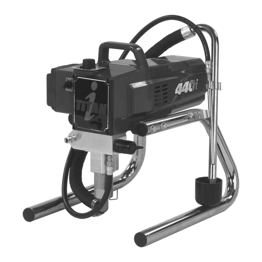
General Description
This airless sprayer is a precision power tool used for spraying many types of materials. Read and follow this instruction manual carefully for proper operating instructions, maintenance, and safety information.

Operation
 This equipment produces a fluid stream at extremely high pressure.
Setup
Perform the following procedure before plugging in the power cord of an electric unit.
- Ensure that the suction set and the return hose are attached and secure.
- Using a wrench, attach a minimum of 50' of 1/4" nylon airless spray hose to the unit. Tighten securely.
- Attach an airless spray gun to the spray hose. Using two wrenches (one on the gun and one on the hose), tighten securely.
NOTE: Do not attach the tip to the spray gun yet. Remove the tip if it is already attached.
![warning]() Make sure all airless hoses and spray guns are electrically grounded and rated for at least 3200 psi (21.1 MPa) fluid pressure.
Make sure all airless hoses and spray guns are electrically grounded and rated for at least 3200 psi (21.1 MPa) fluid pressure. - Make sure the pressure control knob is in its OFF position in the black zone.
- Make sure the ON/OFF switch is in its OFF position.
- Fill the oil cup with one tablespoon of piston seal lubricant (Piston Lube).
![]()
Never operate unit for more than ten seconds without fluid. Operating this unit without fluid will cause unnecessary wear to the packings. - Make sure the electrical service is 120V, 15 amp minimum.
- Plug the power cord into a properly grounded outlet at least 25' from the spray area.
![]()
Always use a minimum 12 gauge, three-wire extension cord with a grounded plug. Never remove the third prong or use an adapter.
Preparing a New Sprayer
If this unit is new, it is shipped with test fluid in the fluid section to prevent corrosion during shipment and storage. This fluid must be thoroughly cleaned out of the system with mineral spirits before you begin spraying.

Always keep the trigger lock on the spray gun in the locked position while preparing the system.
- Place the suction tube into a container of mineral spirits.
- Place the return hose into a metal waste container.
- Set the pressure to minimum by turning the pressure control knob to the "Min" setting in the yellow zone.

- Move the PRIME/SPRAY valve down to the PRIME position.
- Turn the unit on by moving the ON/OFF switch to the ON position.
- Allow the sprayer to run for 15–30 seconds to flush the test fluid out through the return hose and into the waste container.
- Turn the unit off by moving the ON/OFF switch to the OFF position.

Preparing to Paint
Before painting, it is important to make sure that the fluid in the system is compatible with the paint that is going to be used.
NOTE: Incompatible fluids and paint may cause the valves to become stuck closed, which would require disassembly and cleaning of the sprayer's fluid section.
Always keep the trigger lock on the spray gun in the locked position while preparing the system.
- Place the suction tube into a container of the appropriate solvent. Examples of the appropriate solvent are water for latex paint or mineral spirits for oil-based paints.
- Place the return hose into a metal waste container.
- Set the pressure to minimum by turning the pressure control knob to the "Min" setting in the yellow zone.
![]()
- Move the PRIME/SPRAY valve down to the PRIME position.
- Turn the unit on by moving the ON/OFF switch to the ON position.
- Allow the sprayer to run for 15–30 seconds to flush the old solvent out through the return hose and into the metal waste container.
- Turn the unit off by moving the ON/OFF switch to the OFF position.
NOTE: Make sure that the spray gun does not have a tip or tip guard installed. - Move the PRIME/SPRAY valve up to the SPRAY position.
- Turn the unit on.
- Unlock the gun by turning the gun trigger lock to the unlocked position.
![warning]() Ground the gun by holding it against the edge of the metal container while flushing. Failure to do so may lead to a static electric discharge, which may cause a fire.
Ground the gun by holding it against the edge of the metal container while flushing. Failure to do so may lead to a static electric discharge, which may cause a fire.
![]()
- Trigger the gun into the metal waste container until the old solvent is gone and fresh solvent is coming out of the gun.
- Lock the gun by turning the gun trigger lock to the locked position.
![]()
- Set down the gun and increase the pressure by turning the pressure control knob slowly clockwise into the green zone.
- Check the entire system for leaks. If leaks occur, follow the "Pressure Relief Procedure" in this manual before tightening any fittings or hoses.
- Follow the "Pressure Relief Procedure" in this manual before changing from solvent to paint.
![warning]() Be sure to follow the pressure relief procedure when shutting down the sprayer for any purpose, including servicing or adjusting any part of the spray system, changing or cleaning spray tips, or preparing for cleanup.
Be sure to follow the pressure relief procedure when shutting down the sprayer for any purpose, including servicing or adjusting any part of the spray system, changing or cleaning spray tips, or preparing for cleanup.


Painting
- Place the suction tube into a container of paint.
- Place the return hose into a metal waste container.
- Set the pressure to minimum by turning the pressure control knob to the "Min" setting in the yellow zone.
![]()
- Move the PRIME/SPRAY valve down to the PRIME position.
- Turn the unit on by moving the ON/OFF switch to the ON position.
- Allow the sprayer to run until paint is coming through the return hose into the metal waste container.
- Turn the unit off by moving the ON/OFF switch to the OFF position.
- Remove the return hose from the waste container and place it in its operating position above the container of paint.
- Move the PRIME/SPRAY valve up to the SPRAY position.
- Turn the unit on.
- Unlock the gun by turning the gun trigger lock to the unlocked position.
![warning]() Ground the gun by holding it against the edge of the metal container while flushing. Failure to do so may lead to a static electric discharge, which may cause a fire.
Ground the gun by holding it against the edge of the metal container while flushing. Failure to do so may lead to a static electric discharge, which may cause a fire.
![]()
- Trigger the gun into the metal waste container until all air and solvent is flushed from the spray hose and paint is flowing freely. from the gun.
- Lock the gun by turning the gun trigger lock to the locked position.
![]()
- Turn the unit off.
- Attach tip guard and tip to the gun as instructed by the tip guard or tip manuals.
![warning]() POSSIBLE INJECTION HAZARD.
POSSIBLE INJECTION HAZARD.
Do not spray without the tip guard in place. Never trigger the gun unless the tip is in either the spray or the unclog position. Always engage the gun trigger lock before removing, replacing or cleaning tip. - Turn the unit on.
- Increase the pressure by turning the pressure control knob slowly clockwise toward the green zone and test the spray pattern on a piece of cardboard. Adjust the pressure control knob until the spray from the gun is completely atomized. Try to keep the pressure control knob at the lowest setting that maintains good atomization.


NOTE: Turning the pressure up higher then needed to atomize the paint will cause premature tip wear and additional overspray.
Electronic Pressure Control Indicators
The following is a description of the indicators on the electronic pressure control.

Pressure Indicator
The pressure indicator shows the current operating pressure of the sprayer. It has three different indications: blinking yellow, solid yellow, and solid green.
Blinking Yellow
When the pressure indicator is blinking yellow, the sprayer is operating between 0 and 200 PSI. A blinking yellow pressure indicator means:
- The sprayer is plugged in and turned "ON"
- The sprayer is at priming pressure (little or no pressure)
- It is safe to move the PRIME/SPRAY valve between positions
- It is safe to change or replace the spray tip
NOTE: If the pressure indicator begins blinking yellow when the pressure control knob is set at a higher pressure and the PRIME/SPRAY valve is in the SPRAY position, either the spray tip is worn or the sprayer is in need of service/repair.
Solid Yellow
When the pressure indicator is solid yellow, the sprayer is operating between 200 and 1800 PSI. A solid yellow pressure indicator means:
- The sprayer is at the proper pressure setting for spraying stain, lacquer, varnish, and multi-colors
- If the pressure indicator goes to solid yellow when the pressure is set so that it starts at solid green, it indicates one of the following:
- Tip Wear Indicator — when spraying with latex or at high pressure the solid yellow appears. This means the tip is worn and needs to be replaced.
- Tip Too Large — when a tip that is too large for the sprayer is put in the gun, the pressure indicator will turn from solid green to solid yellow.
- Fluid Section Wear — if a solid yellow pressure indicator appears when using a new tip and the pressure is set at maximum, service may be required (worn packings, worn piston, stuck valve, etc...).
Solid Green
When the pressure indicator is solid green, the sprayer is operating between 1800 and 3200 PSI. A solid green pressure indicator means:
- The sprayer is at the proper pressure setting for sprayingoil-based and latex house paints
- The sprayer is operating at peak performance at a high pressure setting
Motor Running Indicator
The Motor Running indicator is on when the motor is commanded to run. This indicator is used by service centers to troubleshoot motor problems.
Pressure Relief Procedure
Be sure to follow the pressure relief procedure when shutting the unit down for any purpose, including servicing or adjusting any part of the spray system, changing or cleaning spray tips, or preparing for cleanup.
- Lock the gun by turning the gun trigger lock to the locked position.
![]()
- Turn the unit off by moving the ON/OFF switch to the OFF position.
- Turn the pressure control knob counterclockwise to its OFF position in the black zone.
- Unlock the gun by turning the gun trigger lock to the unlocked position.
- Hold the metal part of the gun firmly to the side of a metal container to ground the gun and avoid a build up of static electricity.
![]()
- Trigger the gun to remove any pressure that may still be in the hose.
- Lock the gun by turning the gun trigger lock to the locked position.
- Move the PRIME/SPRAY valve down to the PRIME position.


Spraying
POSSIBLE INJECTION HAZARD
Do not spray without the tip guard in place. Never trigger the gun unless the tip is in either the spray or the unclog position. Always engage the gun trigger lock before removing, replacing, or cleaning tip.
Spraying Technique
The following techniques, if followed, will assure professional painting results.
Hold the gun perpendicular to the surface and always at equal distance from the surface. Depending on the type of material, surface, or desired spray pattern, the gun should be held at a distance of 12 to 14 inches (30 to 35 cm).
Move the gun either across or up and down the surface at a steady rate. Moving the gun at a consistent speed conserves material and provides even coverage. The correct spraying speed allows a full, wet coat of paint to be applied without runs or sags.
Holding the gun closer to the surface deposits more paint on the surface and produces a narrower spray pattern. Holding the gun farther from the surface produces a thinner coat and wider spray pattern. If runs, sags, or excessive paint occur, change to a spray tip with a smaller orifice. If there is an insufficient amount of paint on the surface or you desire to spray faster, a larger orifice tip should be selected.
Maintain uniform spray stroke action. Spray alternately from left to right and right to left. Begin movement of the gun before the trigger is pulled.

Avoid arcing or holding the gun at an angle. This will result in an uneven finish.

Proper lapping (overlap of spray pattern) is essential to an even finish. Lap each stroke. If you are spraying horizontally, aim at the bottom edge of the preceding stroke, so as to lap the previous pattern by 50%.

For corners and edges, split the center of the spray pattern on the corner or edge and spray vertically so that both adjoining sections receive approximately even amounts of paint.

When spraying with a shield, hold it firmly against the surface. Angle the spray gun slightly away from the shield and toward the surface. This will prevent paint from being forced underneath.
Shrubs next to houses should be tied back and covered with a canvas cloth. The cloth should be removed as soon as possible. Titan gun extensions are extremely helpful in these situations.
Nearby objects such as automobiles, outdoor furniture, etc. should be moved or covered whenever in the vicinity of a spray job. Be careful of any other surrounding objects that could be damaged by overspray.
Practice
- Be sure that the paint hose is free of kinks and clear of objects with sharp cutting edges.
- Turn the pressure control knob counterclockwise to its to its lowest setting.
- Turn the PRIME/SPRAY valve up to its SPRAY position.
- Turn the pressure control knob clockwise to its highest setting. The paint hose should stiffen as paint begins to flow through it.
- Unlock the gun trigger lock.
- Trigger the spray gun to bleed air out of the hose.
- When paint reaches the spray tip, spray a test area to check the spray pattern.
- Use the lowest pressure setting necessary to get a good spray pattern. If the pressure is set too high, the spray pattern will be too light. If the pressure is set too low, tailing will appear or the paint will spatter out in gobs rather than in a fine spray.
![]()

Cleanup
Special cleanup instructions for use with flammable solvents:
- Always flush spray gun preferably outside and at least one hose length from spray pump.
- If collecting flushed solvents in a one gallon metal container, place it into an empty five gallon container, then flush solvents.
- Area must be free of flammable vapors.
- Follow all cleanup instructions.
The sprayer, hose, and gun should be cleaned thoroughly after daily use. Failure to do so permits material to build up, seriously affecting the performance of the unit.
Always spray at minimum pressure with the gun nozzle tip removed when using mineral spirits or pass pass pass any other solvent to clean the sprayer, hose, or gun. Static electricity buildup may result in a fire or explosion in the presence of flammable vapors.
- Follow the "Pressure Relief Procedure" found in the Operation section of this manual.
- Remove the gun tip and tip guard and clean with a brush using the appropriate solvent.
- Place the suction tube into a container of the appropriate solvent. Examples of the appropriate solvent are water for latex paint or mineral spirits for oil-based paints.
- Place the return hose into a metal waste container.
- Move the PRIME/SPRAY valve down to its PRIME position.
- Set the pressure to Turbo PulseClean by turning the pressure control knob to its CLEAN position in the red zone.
![]()
- Turn the unit on by moving the ON/OFF switch to the ON position.
- Allow the solvent to circulate through the unit and flush the paint out of the return hose into the metal waste container.
- Turn the unit off by moving the ON/OFF switch to the OFF position.
- Move the PRIME/SPRAY valve up to its SPRAY position.
- Turn the unit on.
![warning]() Ground the gun by holding it against the edge of the metal container while flushing. Failure to do so may lead to a static electric discharge, which may cause a fire.
Ground the gun by holding it against the edge of the metal container while flushing. Failure to do so may lead to a static electric discharge, which may cause a fire. - Trigger the gun into the metal waste container until the paint is flushed out of the hose and solvent is coming out of the gun.
- Continue to trigger the spray gun into the waste container until the solvent coming out of the gun is clean.
NOTE: For long-term or cold weather storage, pump mineral sprits through the entire system.
For short-term storage when using latex paint, pump water mixed with Titan Liquid Shield through the entire system (see the Accessories section of this manual for part number). - Follow the "Pressure Relief Procedure" found in the Operation section of this manual.
- Unplug the unit and store in a clean, dry area.
![]()
Do not store the unit under pressure.

Maintenance
 Before proceeding, follow the Pressure Relief Procedure outlined previously in this manual. Additionally, follow all other warnings to reduce the risk of an injection injury, injury from moving parts or electric shock. Always unplug the sprayer before servicing!
General Repair and Service Notes
The following tools are needed when repairing this sprayer:
| Phillips Screwdriver | 3/8" Hex Wrench |
| Needle Nose Pliers | 5/16" Hex Wrench |
| Adjustable Wrench | 1/4" Hex Wrench |
| Rubber Mallet | 3/16" Hex Wrench |
| Flat-blade Screwdriver | 5/32" Hex Wrench |
- Before repairing any part of the sprayer, read the instructions carefully, including all warnings.
![]()
Never pull on a wire to disconnect it. Pulling on a wire could loosen the connector from the wire. - Test your repair before regular operation of the sprayer to be sure that the problem is corrected. If the sprayer does not operate properly, review the repair procedure to determine if everything was done correctly. Refer to the Troubleshooting Charts to help identify other possible problems.
- Make certain that the service area is well ventilated in case solvents are used during cleaning. Always wear protective eye wear while servicing. Additional protective equipment may be required depending on the type of cleaning solvent. Always contact the supplier of solvents for recommendations.
Replacing the Motor

- Unplug the unit.
- Loosen and remove the four motor cover screws. Remove the motor cover.
- Disconnect the black and red wires coming from the pump housing. Disconnect the black and red wires from the capacitors. Disconnect the black and red wires from the motor.
- Remove the capacitors from their mounting clip.
- Loosen and remove the four motor mounting screws.
- Pull the motor out of the pump housing.
NOTE: If the motor will not dislodge from the pump housing:- Remove the front cover plate.
- Using a rubber mallet, carefully tap on the front of the motor crankshaft that extends through the connecting rod.
- With the motor removed, inspect the gears in the pump housing for damage or excessive wear. Replace the gears, if necessary.
- Install the new motor into the pump housing.
NOTE: Rotate the motor fan manually until the armature gear engages with the mating gear in the pump housing. - Secure the motor with the four motor mounting screws.
- Push the capacitors into their clip on the new motor.
- Reconnect the wires (refer to the electrical schematic in the Parts List section of this manual).
- Slide the motor cover over the motor. Secure the motor cover with the four motor cover screws.
Replacing the Motor Brushes
Perform this procedure using Motor Brush Kit P/N 704-276.
- Loosen and remove the four motor cover screws. Remove the motor cover.
- Loosen and remove the two shroud screws. Remove the shroud.
- Using a small screwdriver, pry off the two plastic brush covers.
- Disconnect the black and red wires from the motor brushes. Remove the motor brushes.
- Install the new motor brushes and snap on the plastic brush covers.
- Reconnect the black and red wires from the motor brushes (refer to the electrical schematic in the Parts List section of this manual).
- Position the shroud over the motor fan. Secure the shroud with the two shroud screws.
- Slide the motor cover over the motor. Secure the motor cover with the four motor cover screws.
Replacing the Gears

- Loosen and remove the four motor cover screws. Remove the motor cover.
- Disconnect the black and red wires coming from the pump housing.
- Loosen and remove the four motor mounting screws.
- Pull the motor out of the pump housing.
NOTE: If the motor will not dislodge from the pump housing:- Remove the front cover plate.
- Using a rubber mallet, carefully tap on the front of the motor crankshaft that extends through the connecting rod.
- Inspect the armature gear on the end of the motor for damage or excessive wear. If this gear is completely worn out, replace the entire motor.
- Remove and inspect the 2nd stage gear for damage or excessive wear. Replace if necessary.
- Remove and inspect the gear and crank assembly for damage or excessive wear. Replace if necessary.
- Reassemble the pump by reversing the above steps. During reassembly, make sure the thrust washers is in place.
NOTE: Refill the gear box with five ounces of Lubriplate (P/N 314-171).
Replacing the Transducer

- Loosen and remove the four front cover screws. Remove the front cover.
- Stop the sprayer at the bottom of its stroke so that the piston is in its lowest position. Turn off and unplug the sprayer.
![warning]() Before proceeding, follow the Pressure Relief Procedure outlined previously in this manual. Additionally, follow all other warnings to reduce the risk of an injection injury, injury from moving parts or electric shock. Always unplug the sprayer before servicing!
Before proceeding, follow the Pressure Relief Procedure outlined previously in this manual. Additionally, follow all other warnings to reduce the risk of an injection injury, injury from moving parts or electric shock. Always unplug the sprayer before servicing! - Tilt the pump back for easy access to the fluid section.
- Using a 3/8" hex wrench, loosen and remove the two pump block mounting screws.
- Pull the pump block down approximately 1/2" from the pump housing to clear the transducer.
- Slide the pump block and piston rod forward until the piston rod is out of the T-slot on the connecting rod.
- Loosen and remove the four electronic pressure control (EPC) mounting screws.
- Pull back the EPC for access to the transducer plug-in.
- Unplug the transducer connection from EPC board location "JP3" (refer to the electrical schematic in the Parts List section of this manual).
- Using an 1/8" hex wrench, loosen and remove the set screw from the bottom of the pump housing.
- Slide the transducer assembly out of the bottom of the pump housing.
- Install the new transducer assembly into the pump housing.
- Thread the set screw into the pump housing and tighten securely.
- Plug the transducer connection into the EPC board at location "JP3" (refer to the electrical schematic in the Parts List section of this manual).
- Reassemble the pump by reversing steps 1–8.
![]()
Make sure the transducer is aligned properly with the hole in the pump block during reassembly. Improper alignment may cause damage to the transducer gasket.
Replacing the PRIME/SPRAY Valve
Perform the following procedure using PRIME/SPRAY valve replacement kit P/N 700-258.

- Push the groove pin out of the valve handle.
- Remove the valve handle and the cam base.
- Using a wrench, loosen and remove the valve housing assembly.
- Make sure the gasket is in place and thread the new valve housing assembly into the pump block. Tighten securely with wrench.
- Place the cam base over the valve housing assembly. Lubricate the cam base with grease and line up the cam with the pump block.
- Line up the hole on the valve stem with the hole in the valve handle.
- Insert the groove pin into the valve handle and through the valve stem to secure the valve handle in position.
Servicing the Fluid Section
Use the following procedures to service the valves and repack the fluid section. Perform the following steps before performing any maintenance on the fluid section.
- Loosen and remove the four front cover screws. Remove the front cover.
- Stop the sprayer at the bottom of its stroke so that the piston is in its lowest position. Turn off and unplug the sprayer.
![warning]() Before proceeding, follow the Pressure Relief Procedure outlined previously in this manual. Additionally, follow all other warnings to reduce the risk of an injection injury, injury from moving parts or electric shock. Always unplug the sprayer before servicing!
Before proceeding, follow the Pressure Relief Procedure outlined previously in this manual. Additionally, follow all other warnings to reduce the risk of an injection injury, injury from moving parts or electric shock. Always unplug the sprayer before servicing! - Unscrew the return hose assembly from the pump block.
- Remove the retaining clip that holds the suction set in the foot valve. Pull the suction set out of the foot valve.
- Tilt the pump back for easy access to the fluid section.
Servicing the Valves
The design of Titan's fluid section allows access to the foot valve and seat as well as the outlet valve and seat without completely disassembling the fluid section. It is possible that the valves may not seat properly because of debris stuck in the foot valve seat or outlet valve seat. Use the following instructions to clean the valves and reverse or replace the seats.

- Using a wrench, loosen and remove the foot valve housing from the pump block.
- Clean out any debris in the foot valve housing and examine the valve housing and seat. If the seat is damaged, reverse or replace the seat.
- Using a 3/8" hex wrench, loosen and remove the outlet valve housing from the piston rod.
NOTE: Always service the outlet valve with the piston rod attached to the pump. This will prevent the piston rod from rotating during disassembly of the outlet valve.
![]()
- Clean out any debris and examine the valve housing and seat. If the seat is damaged, reverse or replace the seat.
- Remove, clean, and inspect the upper cage and upper ball. Replace if they are worn or damaged.
- Reassemble the valves by reversing the steps above.

Repacking the Fluid Section
NOTE: The factory-installed packings are black in color. The replacement packings in the packing replacement kit are white.

- Remove the foot valve and outlet valve assemblies using the steps in the "Servicing the Valves" procedure above.
- Using 3/8" a hex wrench, loosen and remove the two pump block mounting screws.
- Pull the pump block down approximately 1/2" from the pump housing.
- Slide the pump block and piston rod forward until the piston rod is out of the T-slot on the connecting rod.
- Slide the piston rod out through the bottom of the pump block
- Loosen and remove the retainer nut and piston guide from the pump block.
- Remove the upper and lower packings from the pump block.
- Clean the pump block and install the new upper and lower packings. Refer to the illustration below for proper packing orientation.
![]()
- Inspect the piston rod for wear and replace if necessary.
- Reassemble the outlet valve assembly into the piston rod. Tighten the outlet valve housing with a wrench until secure.
NOTE: Use the T-slot on the connecting rod to hold the piston rod in position while securing the outlet valve housing.
![]()
Never use a wrench on the piston itself.
This could cause damage to the piston and cause leakage. - Insert the piston guide into the retainer nut. Thread the retainer nut into the pump block until it is hand tight.
- Slide the piston guide tool (included in the repacking kit) over the top of the piston rod and insert the piston rod through the bottom of the pump block. Using a rubber mallet, tap the bottom of the piston rod lightly until the piston rod is in position in the pump block.
NOTE: Coat the piston guide tool and the piston rod with grease before inserting them into the pump block. - Using a wrench, tighten the retainer nut securely.
- Slide the top of the piston rod into the T-slot on the connecting rod.
- Position the pump block underneath the pump housing and push up until it rests against the pump housing.
![]()
Make sure the transducer is aligned properly with the hole in the pump block during reassembly. Improper alignment may cause damage to the transducer gasket. - Thread the pump block mounting screws through the pump block and into the pump housing. Tighten securely.
- Reassemble the foot valve assembly into the pump block.
- Insert the elbow on the suction set into the bottom of the foot valve. Position the retaining clip into the foot valve to secure the suction set assembly.
- Thread the return hose into the pump block and tighten securely.
- Place the front cover on the pump housing and secure in position using the four front cover screws.
- Turn on the sprayer by following the procedure in the "Operation" section of this manual and check for leaks.
NOTE: Repacking kit P/N 730-401 is available. For best results use all parts supplied in this kit.

Replacing the Filters
Pump Filter

- Loosen and remove the filter housing.
- Turning clockwise, unscrew the filter from the pump block.
NOTE: Left-handed threads require turning the filter clockwise to remove. If the filter breaks off in the pump block, use a small wood screw to remove. - Inspect the seal. Based on inspection, clean or replace the seal.
- Turning counterclockwise, thread the new or cleaned filter into the pump block.
- Slide the filter housing over the filter and thread it into the pump block until secure.
Gun Filter

- Move the gun trigger lock to the unlocked position.
- Loosen and remove the handle from the gun body.
- Turning clockwise, unscrew the filter from the gun body.
NOTE: Left-handed threads require turning the filter clockwise to remove. - Turning counterclockwise, screw the new or cleaned filter into the gun body.
- Make sure the handle seal is in position and thread the handle into the gun body until secure.
- Move the gun trigger lock to the locked position.
NOTE: For more detail, part number information, and assembly drawings at larger scale, please see the LX-80 Professional Airless Gun Owner's Manual (P/N 313-012).
Troubleshooting
Airless Sprayer
| Problem | Cause | Solution |
| Electric motor won't run |
|
|
| Sprayer won't prime |
|
|
| Insufficient material flow |
|
|
| Sprayer will not maintain pressure |
|
|
| Not enough pressure |
|
|
| Excessive surge at spray gun |
|
|
| Paint leaks into oil cup |
|
|
Airless Gun
| Problem | Cause | Solution |
| Spitting gun |
|
|
| Gun will not shut off |
|
|
| Gun does not spray |
|
|
Spray Patterns
| Problem | Cause | Solution |
| Tails |
|
|
| Heavy centered pattern |
|
|
| Distorted pattern |
|
|
| Pattern expanding and contracting (Surge) |
|
|
Important Safety Information
- Read all safety information before operating the equipment.
This symbol indicates a hazardous situation, which, if not not avoided could result in death or serious injury.
To reduce the risks of fire or explosion, electrical shock and the injury to persons, read and understand all instructions included in this manual. Be familiar with the controls and proper usage of the equipment.
HAZARD: INJECTION INJURY

A high pressure paint stream produced by this equipment can pierce the skin and underlying tissues, leading to serious injury and possible amputation. See a physician immediately.
DO NOT TREAT AN INJECTION INJURY AS A SIMPLE CUT! Injection can lead to amputation. See a physician immediately.
The maximum operating range of the sprayer is 3200 PSI / 22.1 MPa fluid pressure.
PREVENTION:
- NEVER aim the gun at any part of the body.
- Do not aim the gun at, or spray any person or animal.
- NEVER allow any part of the body to touch the fluid stream. DO NOT allow body to touch a leak in the fluid hose.
- NEVER put your hand in front of the gun. Gloves will not provide protection against an injection injury.
- ALWAYS lock the gun trigger, shut the pump off, and release all pressure before servicing, cleaning the tip or guard, changing tip, or leaving unattended. Pressure will not be released by turning off the motor. The PRIME/SPRAY valve or pressure bleed valve must be turned to their appropriate positions to relieve system pressure. Refer to the PRESSURE RELIEF PROCEDURE described in this manual.
- ALWAYS keep the tip guard in place while spraying. The tip guard provides some protection but is mainly a warning device.
- ALWAYS remove the spray tip before flushing or cleaning the system.
- Paint hose can develop leaks from wear, kinking and abuse. A leak can inject material into the skin. Inspect the hose before each use. Do not use hose to lift or pull equipment.
- NEVER use a spray gun without a working trigger lock and trigger guard in place.
- All accessories must be rated at or above 3200 PSI / 22.1 MPa. This includes spray tips, guns, extensions, and hose.
- Do not leave the unit energized or under pressure while unattended. When the unit is not in use, turn off the unit and relieve the pressure in accordance with the PRESSURE RELIEF PROCEDURE described in this manual.
- Verify that all connections are secure before operating the unit. Unsecured parts may eject at great force or leak a high pressure fluid stream causing severe injury.
- Always engage the trigger lock when not spraying. Verify the trigger lock is functioning properly.
NOTE TO PHYSICIAN:
Injection into the skin is a traumatic injury. It is important to treat the injury as soon as possible. DO NOT delay treatment to research toxicity. Toxicity is a concern with some coatings injected directly into the blood stream. Consultation with a plastic surgeon or reconstructive hand surgeon may be advisable.
HAZARD: HAZARDOUS VAPORS
![]()
Paints, solvents, insecticides, and other materials can be harmful if inhaled or come in contact with the body. Vapors can cause severe nausea, fainting, or poisoning.
PREVENTION:
![]()
Use a respirator or mask if vapors can be inhaled. Read all instructions supplied with the mask to be sure it will provide the necessary protection.- Wear protective eyewear.
- Wear protective clothing as required by coating manufacturer.

HAZARD: EXPLOSION OR FIRE

Solvent and paint fumes can explode or ignite.
Property damage and/or severe injury can occur.
PREVENTION:
- Provide extensive exhaust and fresh air introduction to keep the air within the spray area free from accumulation of flammable vapors. Solvent and paint fumes can explode or ignite.
- Do not spray in a confined area.
![]()
Avoid all ignition sources such as static electric sparks, open flames, pilot lights, electrical appliances, and hot objects. Connecting or disconnecting power cords or working light switches can make sparks. Paint or solvent flowing through the equipment is able to result in static electricity.- Do not smoke in spray area.
- Fire extinguisher must be present and in good working order.
- Place pump at least 25 feet (7.62 meters) from the spray object in a well ventilated area (add more hose if necessary). Flammable vapors are often heavier than air. Floor area must be extremely well ventilated. The pump contains arcing parts that emit sparks and can ignite vapors.
- The equipment and objects in and around the spray area must be properly grounded to prevent static sparks.
- Keep area clean and free of paint or solvent containers, rags and other flammable materials.
- Use only conductive or grounded high pressure fluid hose. Gun must be grounded through hose connections.
- For electric units — power cord must be connected to a grounded circuit.
- Always flush unit into a separate metal container, at low pump pressure, with spray tip removed. Hold gun firmly against side of container to ground container and prevent static sparks.
- Follow the material and solvent manufacturer's warnings and instructions. Know the contents of the paints and solvents being sprayed. Read all Material Safety Data Sheets (MSDS) and container labels provided with the paints and solvents. Follow the paint and solvent manufacturer's safety instructions.
- Use extreme caution when using materials with a flashpoint below 70ºF (21ºC). Flashpoint is the temperature that a fluid can produce enough vapors to ignite.
- Plastic can cause static sparks. Never hang plastic to enclose a spray area. Do not use plastic drop cloths when spraying flammable materials.
- Use lowest possible pressure to flush equipment.
- Do not spray onto pump assembly.
HAZARD: EXPLOSION HAZARD DUE TO INCOMPATIBLE MATERIALS
![]()
Will cause property damage or severe injury.
PREVENTION:
- Do not use materials containing bleach or chlorine.
- Do not use halogenated hydrocarbon solvents such as bleach, mildewcide, methylene chloride and 1,1,1 - trichloroethane. They are not compatible with aluminum.
- Contact your coating supplier about the compatibility of material with aluminum.
HAZARD: GENERAL
Can cause severe injury or property damage.
- Read all instructions and safety precautions before operating equipment.
- Follow all appropriate local, state, and national codes governing ventilation, fire prevention, and operation.
- The United States Government Safety Standards have been adopted under the Occupational Safety and Health Act (OSHA). These standards, particularly part 1910 of the General Standards and part 1926 of the Construction Standards should be consulted.
- Use only manufacturer authorized parts. User assumes all risks and liabilities when using parts that do not meet the minimum specifications and safety requirements of the pump manufacturer.
- All hoses, fittings, and filter parts must be secured before operating spray pump. Unsecured parts can eject at great force or leak a high pressure fluid stream causing severe injury.
- Before each use, check all hoses for cuts, leaks, abrasion or bulging of cover. Check for damage or movement of couplings. Immediately replace the hose if any of these conditions exist. Never repair a paint hose. Replace it with another grounded high-pressure hose.
- Do not kink or over-bend the hose. Airless hose can develop leaks from wear, kinking and abuse. A leak can inject material into the skin.
- Do not expose the hose to temperatures or pressures in excess of those specified by manufacturer.
- Do not spray outdoors on windy days.
- Wear clothing to keep paint off skin and hair.
- Do not operate or spray near children. Keep children away from the equipment at all times.
- Do not overreach or stand on an unstable support. Keep effective footing and balance at all times.
- Use lowest possible pressure to flush equipment.
- Stay alert and watch what you are doing.
- Do not operate the unit when fatigued or under the influence of drugs or alcohol.
- For electric units — Always unplug cord from outlet before working on equipment.
- Do not use the hose as a strength member to pull or lift the equipment.
- Do not lift by cart handle when loading or unloading.
Grounding Instructions
This product must be grounded. In the event of an electrical short circuit, grounding reduces the risk of electric shock by providing an escape wire for the electric current. This product is equipped with a cord having a grounding wire with an appropriate grounding plug. The plug must be plugged into an outlet that is properly installed and grounded in accordance with all local codes and ordinances.
Improper installation of the grounding plug can result in a risk of electric shock.
If repair or replacement of the cord or plug is necessary, do not connect the green grounding wire to either flat blade terminal. The wire with insulation having a green outer surface with or without yellow stripes is the grounding wire and must be connected to the grounding pin.
Check with a qualified electrician or serviceman if the grounding instructions are not completely understood, or if you are in doubt as to whether the product is properly grounded. Do not modify the plug provided. If the plug will not fit the outlet, have the proper outlet installed by a qualified electrician.

Use only a 3-wire extension cord that has a 3-blade grounding plug and a 3-slot receptacle that will accept the plug on the product. Make sure your extension cord is in good condition. When using an extension cord, be sure to use one heavy enough to carry the current your product will draw. An undersized cord will cause a drop in line voltage resulting in loss of power and overheating. A 12 gauge cord is recommended. If an extension cord is to be used outdoors, it must be marked with the suffix W- A after the cord type designation. For example, a designation of SJTW-A would indicate that the cord would be appropriate for outdoor use.
If you have any further questions concerning your TITAN Airless Sprayer, call TITAN:
Customer Service (U.S.): 1-800-526-5362
Fax: 1-800-528-4826
Customer Service (Canada): 1-800-565-8665
Fax: 1-905-856-8496
Customer Service (International): 1-201-405-7520
Fax: 1-201-405-7449
Documents / ResourcesDownload manual
Here you can download full pdf version of manual, it may contain additional safety instructions, warranty information, FCC rules, etc.
Advertisement


Need help?
Do you have a question about the 440i and is the answer not in the manual?
Questions and answers