Table of Contents
Advertisement
Do not use this equipment before reading this manual!
440
Model Number:
120V Complete
Printed in the U. S. A.
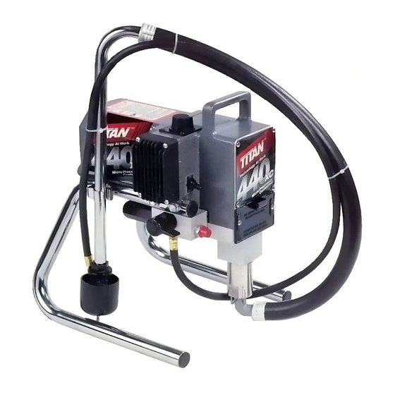
XC Airless Sprayer
700-2000
Owner's Manual
For professional use only
NOTE: This manual contains important warnings
and instructions. Please read and retain for
reference.
0101 © 2001 Titan Tool Inc. All rights reserved. Form No. 313-1434, REV B
Advertisement
Table of Contents

Related Manuals for Titan 440xc


Summary of Contents for Titan 440xc
- Page 1 XC Airless Sprayer Model Number: 120V Complete 700-2000 NOTE: This manual contains important warnings and instructions. Please read and retain for reference. 0101 © 2001 Titan Tool Inc. All rights reserved. Form No. 313-1434, REV B Printed in the U. S. A.
-
Page 2: Table Of Contents
• Follow the material and solvent manufacturer's warnings and instructions. • Use extreme caution when using materials with a flashpoint below 70° F (21° C). Flashpoint is the temperature that a fluid can produce enough vapors to ignite. © Titan Tool Inc. All rights reserved. -
Page 3: Grounding Instructions
• Wear clothing to keep paint off skin and hair. NOTE: Do not use more than 50 feet of extension cord. If you need to paint further than 100 feet from your power source, use more paint hose, not more extension cord. © Titan Tool Inc. All rights reserved. -
Page 4: General Description
8. Plug the power cord into a properly grounded outlet. SPRAY control knob clockwise to Valve increase the pressure until fluid starts to come out of the return hose. Use only enough pressure to keep the fluid coming out. © Titan Tool Inc. All rights reserved. -
Page 5: Operating The Spray Gun
12. Lock the gun by turning the gun trigger lock to the locked position. © Titan Tool Inc. All rights reserved. -
Page 6: Spraying
Shrubs next to houses should be tied back and covered with a canvas cloth. The cloth should be removed as soon as possible. Titan gun extensions are extremely helpful in these situations. Avoid arcing or holding the gun at an angle. This will result in an uneven finish. -
Page 7: Cleanup
Always contact the supplier of solvents Knob 6. Tilt the siphon tube above for recommendations. the material container and 5. If you have any further questions concerning your TITAN allow the unit to pump itself Airless Sprayer, call TITAN: ON/OFF dry through the return tube. -
Page 8: Daily Maintenance
LX -80 Professional Airless Gun Owner's trigger, reverse the spray tip back to the Manual (#313-012). spray pattern setting, and resume spraying. © Titan Tool Inc. All rights reserved. -
Page 9: Accessories
Part No. Description 700-925 ...8 Ounce Individual 700-926 ...1 Quart Individual 700-911 ...Case of 12 (8 ounce bottles) 700-912 ...Case of 12 (1 quart bottles) © Titan Tool Inc. All rights reserved. -
Page 10: Troubleshooting
2. Needle assembly out of adjustment 2. Adjust 3. Dirty gun 3. Clean Gun does not spray 1. No paint 1. Check fluid supply 2. Plugged filter or tip 2. Clean 3. Broken needle in gun 3. Replace © Titan Tool Inc. All rights reserved. -
Page 11: Spray Patterns
Remove restrictions in system; clean tip screen if filter is used. Round pattern 1. Worn tip 1. Replace tip. 2. Fluid too heavy for tip 2. Increase pressure. Thin material. Change nozzle tip. © Titan Tool Inc. All rights reserved. -
Page 12: Français
• Tous les accessoires doivent être homologués pour une pression égale ou supérieure à 3 200 lb/po2 / 221BAR. Cela s'applique, entre autres, aux têtes de pulvérisation, aux accessoires du pistolet et aux flexibles. © Titan Tool Inc. Tous droits réservés. - Page 13 • Ne jamais pulvériser lorsqu'il vente. peinture plus long et non une rallonge plus • Porter des vêtements pour protéger la peau et les longue. cheveux contre tout contact avec la peinture. © Titan Tool Inc. Tous droits réservés.
-
Page 14: Español
Consulte el manual del motor • Todos los accesorios deben tener una capacidad de 3200 para obtener información completa de seguridad. lb/pulg2 / 221BAR o mayor. Esto incluye las boquillas de atomizador, pistolas, extensiones y mangueras. © Titan Tool Inc. Todos los derechos reservados. - Page 15 El enchufe se debe enchufar en una toma de corriente que se haya instalado y conectado a tierra debidamente, de acuerdo con todos los códigos y estatutos locales. © Titan Tool Inc. Todos los derechos reservados.
-
Page 16: Parts Lists And Service Instructions
Always unplug the unit before servicing! Replacement Labels Part # Description Quantity 700-1015 Front cover label .............1 313-175 "Warning/Attention" (label In French).....1 313-1432 Wraparound 440XC label........1 © Titan Tool Inc. All rights reserved. -
Page 17: Motor Assembly
(refer to the electrical schematic in this section of the manual for the proper wire positions). 13. Place the pressure control board over the switch box and secure in position using the four screws. © Titan Tool Inc. All rights reserved. -
Page 18: Gear Box Assembly
700-739 Pump housing .........1 700-161 Pressure control board......1 700-681 Screw ............4 700-720 Fuse, 10A..........1 730-260 Screw ............6 700-646 ON/OFF switch ........1 700-1015 Front plate..........1 700-158 Potentiometer..........1 700-791 Safety plate ..........1 700-197 Transducer assembly......1 © Titan Tool Inc. All rights reserved. -
Page 19: Electrical Schematic
110V -- 440; 550 cord (7). 4. Install the new cord in the reverse order of disassembly. 5. Reinstall the pressure control board (13) and secure in position using the four screws (12). © Titan Tool Inc. All rights reserved. -
Page 20: Fluid Section Assembly
Assembly” parts list) and pull it down and out of the foot valve (21). 5. Remove the siphon assembly by pulling it down and out of the foot valve (21). 4. Tilt the pump back for easy access to the fluid section. © Titan Tool Inc. All rights reserved. -
Page 21: Siphon Assembly
22. Slide the assembled pump housing with the piston assembly onto the connecting rod and secure with the screws (6). Be certain that the outlet hole is facing towards the pump motor. © Titan Tool Inc. All rights reserved. -
Page 22: Filter Block Assembly
NOTE: When using “HOT” solvents, replace Viton o- ring (#8) with alternate PTFE o-ring (P/N 700- 5. Thread the filter housing (1) into the filter block and tighten securely. 897). Install with o-ring tool (P/N 700-890). © Titan Tool Inc. All rights reserved. -
Page 23: Skid Assembly
700-674 End cap..........4 704-092 Leg, left (includes items 2 and 4) ..1 700-781 Drip cup ...........1 700-069 Screw ..........2 700-761 Cord wrap ........1 704-091 Leg, right (includes items 2, 5, and 6) .....1 © Titan Tool Inc. All rights reserved. -
Page 24: Warranty
Warranty Titan Tool, Inc., (“Titan”) warrants that at the time of delivery to the original purchaser for use (“End User”), the equipment covered by this warranty is free from defects in material and workmanship. Titan’s obligation under this warranty is limited to replacing or repairing without charge those parts which, to Titan’s reasonable satisfaction, are shown to be defective within...
Need help?
Do you have a question about the 440xc and is the answer not in the manual?
Questions and answers