Titan IMPACT 440, 0532035, 0532038 Manual
- Owner's manual (48 pages) ,
- Operating manual (26 pages) ,
- Service manual (36 pages)
Advertisement
- 1 GENERAL VIEW OF APPLICATION / DESCRIPTION OF UNIT
- 2 STARTING OPERATION
- 3 SPRAYING
- 4 HANDLING THE HIGH-PRESSURE HOSE
- 5 INTERRUPTION OF WORK
- 6 CLEANING THE UNIT (SHUTTING DOWN)
- 7 REMEDY IN CASE OF FAULTS
- 8 SERVICING
- 9 REPAIRS AT THE UNIT
- 10 SELECTION OF TIP
- 11 SERVICING AND CLEANING OF AIRLESS HARD-METAL TIPS
- 12 SPARE PARTS DIAGRAM
- 13 GENERAL SAFETY INSTRUCTIONS
- 14 SAFETY REGULATIONS FOR AIRLESS SPRAYING
- 15 Documents / Resources
GENERAL VIEW OF APPLICATION / DESCRIPTION OF UNIT
APPLICATION
The unit performance is conceived so that its use is possible on building sites for small- to middle-area dispersion work.
EXAMPLES OF OBJECTS TO BE SPRAYED
The sprayer is able for all common varnishing jobs like doors, door frames, balustrades, furniture, woodencladding, fences, radiators (heating) and steel parts.
COATING MATERIALS
PROCESSIBLE COATING MATERIALS
 Pay attention to the Airless quality of the coating materials to be processed.
Dilutable lacquers and paints or those containing solvents, twocomponent coating materials, dispersions, latex paints, release agents, oils, undercoats, primers, and fillers. No other materials should be used for spraying without Titan's approval.
FILTERING
Despite suction filter and insertion filter in the spray gun, filtering of the coating material is generally advisable. Stir coating material before commencement of work.
Attention: Make sure, when stirring up with motordriven agitators that no air bubbles are stirred in. Air bubbles disturb when spraying and can, in fact, lead to interruption of operation.
VISCOSITY
With this unit it is possible to process highly viscous coating materials of up to around 20.000 MPa·s.
If highly viscous coating materials cannot be taken in by suction, they must be diluted in accordance with the manufacturer's instructions.
TWO-COMPONENT COATING MATERIAL
The appropriate processing time must be adhered to exactly. Within this time rinse through and clean the unit meticulously with the appropriate cleaning materials.
COATING MATERIALS WITH SHARP-EDGED ADDITIONAL MATERIALS
These have a strong wear and tear effect on valves, high-pressure hose, spray gun and tip. The durability of these parts cane be reduced appreciably through this.
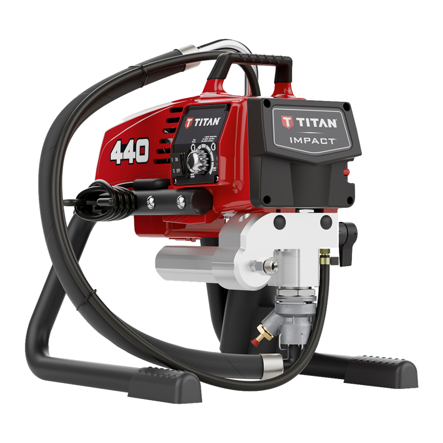
EXPLANATORY DIAGRAM IMPACT 440

LEGEND FOR EXPLANATORY DIAGRAM IMPACT 440
- Spray gun
- High-pressure hose
- Return hose
- Suction hose
- Frame
- Drip cup
- Oil level gauge
- Oil button
- Relief valve
Lever position vertical – PRIME (![]() circulation)
circulation)
Lever position horizontal – SPRAY (![]() )
) - ON/OFF switch
- Control panel indicators
- Pressure control knob
- Oil cup for Piston Lube (Piston Lube prevents increased wear of the packings)
- Pusher stem
- Manometer
 circulation)
 )
)TECHNICAL DATA
| Voltage | |
| 220~240 VAC, 50/60 Hz | |
| Max. current consumption | |
| 4.5 A | |
| Power Cord | |
| 6 m long, 3 x 1.5 mm² | |
| Acceptance capacity | |
| 1035 Watt | |
| Max. operating pressure | |
| 221 bar (22.1 MPa) | |
| Volume flow at 12 MPa (120 bar) with water | |
| 2.0 l/min | |
| Max tip size | |
| 0.023 inch – 0.58 mm | |
| Max. temperature of the coating material | |
| 43°C | |
| Max viscosity | |
| 20.000 MPa·s | |
| Weight | |
| 17.9 kg | |
| Special high-pressure hose | |
| DN 6 mm, 15 m, connection thread M 16 x 1.5 | |
| Dimensions (L X W X H) | |
| 437 x 363 x 416 mm | |
| Altitude | |
| This equipment will operate correctly up to 2000 m above mean sea level | |
| Vibration | |
| Spray gun does not exceed 2.5m/s2 | |
| Max sound pressure level | |
| 80 dB* |
* Place of measurement: 1 m distance from unit and 1.60m above floor, 12 MPa (120 bar) operating pressure, reverberant floor
TRANSPORTATION IN VEHICLE
Secure the unit with a suitable fastening.
STARTING OPERATION
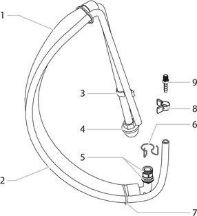
HIGH-PRESSURE HOSE, SPRAY GUN AND SEPARATING OIL
- Screw the pressure gauge (1) to the coating material outlet (Fig. 2, Item 2).
- Screw the high-pressure hose (3) to the coating material outlet (Fig. 2, Item 4).
- Screw the spray gun (5) with the selected tip onto the high-pressure hose.
- Tighten the union nuts at the high-pressure hoses firmly so that coating material does not leak.

- Remove the oil cup cap with a straight-slot screwdriver.
- Fill the oil cup with Piston Lube (Fig. 3). Do not use too much Piston Lube, i.e. ensure that no Piston Lube drips into the coating material container.
![warning]() Attention
Attention
Piston Lube prevents increased wear and tear to the packings. - Replace oil cup cap.
- Press oil button 2-5 times to prime the oiler. Press once for every eight hours of usage to lubricate the fluid section.
- Fully depress the pusher stem to make sure the inlet ball is free.


CONTROL PANEL INDICATORS
The following is a description of the control panel indicators.

SERVICE INDICATOR
The Service indicator is on when the motor is commanded to run. This indicator is used by service centers to troubleshoot motor problems.
PRESSURE INDICATOR
The pressure indicator shows the current operating pressure of the sprayer. It has three different indications: blinking yellow, solid yellow, and solid green.
Blinking Yellow
When the pressure indicator is blinking yellow, the sprayer is operating between 0 and 1.4 MPa (14 bar). A blinking yellow pressure indicator means:
- The sprayer is plugged in and turned "ON"
- The sprayer is at priming pressure (little or no pressure)
- It is safe to move the relief valve between positions
- It is safe to change or replace the spray tip
If the pressure indicator begins blinking yellow when the pressure control knob is set at a higher pressure and the relief valve is in the SPRAY position, either the spray tip is worn or the sprayer is in need of service/repair.
Solid Yellow
When the pressure indicator is solid yellow, the sprayer is operating between 1.4 MPa (14 bar) and 12 MPa (120 bar). A solid yellow pressure indicator means:
- The sprayer is at the proper pressure setting for spraying stain, lacquer, varnish, and multi-colors
Solid Green
When the pressure indicator is solid green, the sprayer is operating between 12 MPa (120 bar) and 23 MPa (230 bar). A solid green pressure indicator means:
- The sprayer is at the proper pressure setting for spraying oil-based and latex house paints
- The sprayer is operating at peak performance at a high pressure setting
- If the pressure indicator goes to solid yellow when the pressure is set so that it starts at solid green, it indicates one of the following:
- Tip Wear Indicator — when spraying with latex or at high pressure the solid yellow appears. This means the tip is worn and needs to be replaced.
- Tip Too Large — when a tip that is too large for the sprayer is put in the gun, the pressure indicator will turn from solid green to solid yellow.
- Fluid Section Wear — if a solid yellow pressure indicator appears when using a new tip and the pressure is set at maximum, service may be required (worn packings, worn piston, stuck valve, etc...).
PRESSURE CONTROL KNOB SETTINGS

- Minimum pressure setting
- Black zone – no pressure generation
- Blue zone – pulsating pressure for cleaning
CONNECTION TO THE MAINS NETWORK
 Attention
The unit must be connected to an appropriatelygrounded safety outlet.
Before connecting the unit to the mains supply, ensure that the line voltage matches that specified on the unit's rating plate.
The connection must be equipped with a residual current protective device with INF ≤ 30 mA.
Titan's accessories program also includes a mobile operator protection device for the electronic supply, which can also be used with other electronic equipment.
CLEANING PRESERVING AGENT WHEN STARTING-UP OF OPERATION INITIALLY

- Immerse the suction tube (Fig. 6, Item 2) return hose (1) into a container with a suitable cleaning agent.
- Turn the pressure control knob counterclockwise (3) to minimum pressure.
- Open the relief valve (4), valve position PRIME (
![]() circulation).
circulation). - Switch the unit (5) ON.
- Wait until the cleaning agent exudes from the return hose.
- Close the relief valve, valve position SPRAY (
![]() spray).
spray). - Pull the trigger of the spray gun.
- Spray the cleaning agent from the unit into an open collecting container.
TAKING THE UNIT INTO OPERATION WITH COATING MATERIAL
- Immerse the suction tube (Fig. 6, Item 2) and return hose (1) into the coating material container.
- Turn the pressure control knob counterclockwise (3) to minimum pressure.
- Open the relief valve (4), valve position PRIME (
![]() circulation).
circulation). - Switch the unit (5) ON.
- Wait until the coating material exudes from the return hose.
- Close the relief valve, valve position SPRAY (
![]() spray).
spray). - Trigger the spray gun several times and spray into a collecting container until the coating material exits the spray gun without interruption.
- Increase the pressure by slowly turning up the pressure control knob.
Check the spray pattern and increase the pressure until the atomization is correct.
Always turn the pressure control knob to the lowest setting with good atomization. - The unit is ready to spray.
SPRAYING

Injection hazard. Do not spray without the tip guard in place. NEVER trigger the gun unless the tip is completely turned to either the spray or the unclog position. ALWAYS engage the gun trigger lock before removing, replacing or cleaning tip.
- The key to a good paint job is an even coating over the entire surface. Keep your arm moving at a constant speed and keep the spray gun at a constant distance from the surface. The best spraying distance is 10-12 inches (25 to 30 cm) between the spray tip and the surface.


- Keep the spray gun at right angles to the surface. This means moving your entire arm back and forth rather than just flexing your wrist. Keep the spray gun perpendicular to the surface, otherwise one end of the pattern will be thicker than the other.


- Trigger gun after starting the stroke. Release the trigger before ending the stroke. The spray gun should be moving when the trigger is pulled and released. Overlap each stroke by about 30%. This will ensure an even coating.


If very sharp edges result or if there are streaks in the spray jet – increase the operating pressure or dilute the coating material.
HANDLING THE HIGH-PRESSURE HOSE
| | The unit is equipped with a high-pressure hose specially suited for piston pumps. |
| | Danger of injury through leaking high-pressure hose. Replace any damaged high-pressure hose immediately. Never repair defective high-pressure hoses yourself! |
The high-pressure hose is to be handled with care. Avoid sharp bends and folds: the smallest bending radius is about 8" (20 cm).
Do not drive over the high-pressure hose. Protect against sharp objects and edges.
Never pull on the high-pressure hose to move the device.
Make sure that the high-pressure hose cannot twist. This can be avoided by using a Titan spray gun with a swivel joint and a hose system.
| When using the high-pressure hose while working on scaffolding, it is best to always guide the hose along the outside of the scaffolding. |
| The risk of damage rises with the age of the high-pressure hose. Titan recommends replacing high-pressure hoses after 6 years. |
| Use only Titan original-high-pressure hoses in order to ensure functionality, safety and durability. |
INTERRUPTION OF WORK
- Open the relief valve, valve position PRIME (
![]() circulation).
circulation). - Switch the unit OFF.
- Turn the pressure control knob counterclockwise to minimum pressure.
- Pull the trigger of the spray gun in order to release the pressure from the high-pressure hose and spray gun.
- Secure the spray gun, refer to the operating manual of the spray gun.
- If a standard tip is to be cleaned.
If a non-standard tip is installed, proceed according to the relevant operating manual. - Depending on the model, leave the suction tube or the suction hose and return hose immersed in the coating material or swivel or immerse it into a corresponding cleaning agent.
 circulation).
| Attention | If fast-drying or two-component coating material is used, ensure that the unit is rinsed with a suitable cleaning agent within the processing time. |
CLEANING THE UNIT (SHUTTING DOWN)
| A clean state is the best method of ensuring operation without problems. After you have finished spraying, clean the unit. Under no circumstances may any remaining coating material dry and harden in the unit. |
| The cleaning agent used for cleaning (only with an ignit ion point above 21°C) must be suitable for the coating material used. |
|
|
- Remove suction hose from the coating material.
- Close the relief valve, valve position SPRAY (
![]() spray).
spray). - Switch the unit ON.
![warning]() Attention
Attention The container must be earthed in case of coating materials which contain solvents. ![warning]()
![]()
Do not pump or spray into a container with a small opening (bunghole)! - Pull the trigger of the spray gun in order to pump the remaining coating material from the suction hose, highpressure hose and the spray gun into an open container.
- Immerse suction hose with return hose into a container with a suitable cleaning agent.
- Turn the pressure control knob counterclockwise to minimum pressure.
- Open the relief valve, valve position PRIME (
![]() circulation).
circulation). - Pump a suitable cleaning agent in the circuit for a few minutes.
- Close the relief valve, valve position SPRAY (
![]() spray).
spray). - Pull the trigger of the spray gun.
- Pump the remaining cleaning agent into an open container until the unit is empty.
- Switch the unit OFF.

CLEANING UNIT FROM OUTSIDE
| | First of all pull out mains plug from socket. |
| Attention | Danger of short circult through penetrating water! Never spray down the unit with high-pressure or high-pressure steam cleaners. Do not put the high-pressure hose into solvents. Use only a wet cloth to wipe down the outside of the hose. |
Wipe down unit externally with a cloth which has been immersed in a suitable cleaning agent.
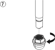
SUCTION FILTER
| A clean suction filter always guarantees maximum feed quantity, constant spraying pressure and problem-free functioning of the unit. |
- Screw off the filter (Fig. 7) from suction tube.
![]()
- Clean or replace the filter.
Carry out cleaning with a hard brush and an appropriate cleaning agent.
CLEANING THE HIGH-PRESSURE FILTER
Clean the filter cartridge regularly. A soiled or clogged high-pressure filter can cause a poor spray pattern or a clogged tip.
- Turn the pressure control knob counterclockwise to minimum pressure.
- Open the relief valve, valve position PRIME (
![]() circulation).
circulation). - Switch the unit OFF.
![warning]() Unplug the power plug from the outlet.
Unplug the power plug from the outlet. - Unscrew the filter housing (Fig. 8, Item 1) with a strap wrench.

- Turning clockwise, unscrew the filter (2) from the pump manifold (3).
- Clean all the parts with the corresponding cleaning agent. If necessary, replace the filter cartridge.
- Check the O-ring (4), replace it if necessary.
- Turning counterclockwise, screw the new or cleaned filter into the pump manifold.
- Screw in filter housing (1) and tighten it as far as possible with the strap wrench.

CLEANING AIRLESS SPRAY GUN
Clean the spray gun after each use.
- Rinse airless spray gun with an appropriate cleaning agent.
- Clean tip thoroughly with appropriate cleaning agent so that no coating material residue remains.
- Thoroughly clean the outside of the airless spray gun.
INTAKE FILTER IN AIRLESS SPRAY GUN (FIG. 9)
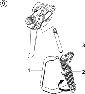
- Unclip the top of the trigger guard (1) from the gun head.
- Using the bottom of the trigger guard as a wrench, loosen and remove the handle assembly (2) from the gun head.
- Pull the old filter (3) out of the gun head. Clean or replace.
- Slide the new filter, tapered end first, into the gun head.
- Thread the handle assembly into the gun head. Tighten with the trigger wrench.
- Snap the trigger guard back onto the gun head.
REMEDY IN CASE OF FAULTS
| Type of malfunction | Possible cause | Measures for eliminating the malfunction |
Unit does not start |
|
|
Unit does not draw in material |
|
|
| Unit draws in material, but the pressure does not build up |
|
|
| Coating material exits at the top of the fluid section |
|
|
Increased pulsation at the spray gun |
|
|
Poor spray pattern |
|
|
Unit loses power |
|
|
Pump over-pressurizes and will not shut off |
|
|
 spray).
  circulation).
 SERVICING
GENERAL SERVICING
Servicing of the unit should be carried out once annually by the TITAN service.
- Check high-pressure hoses, device connecting line and plug for damage.
- Check the inlet valve, outlet valve and filter for wear.
HIGH-PRESSURE HOSE
Inspect the high-pressure hose visually for any notches or bulges, in particular at the transition in the fittings. It must be possible to turn the union nuts freely.
The risk of damage rises with the age of the high-pressure hose. Titan recommends replacing high-pressure hoses after 6 years.
REPAIRS AT THE UNIT
Switch the unit OFF. Before all repair work: Unplug the power plug from the outlet.
RELIEF VALVE
Attention
The valve housing (4) should not be repaired. If worn, it should always be replaced with a new one.

- Use a drift punch of 2 mm to remove the grooved pin (Fig. 10, Item 1) from the relief valve handle (2).
- Remove the relief valve handle (2) and cam base (3).
- Using a wrench, remove the valve housing (4) from the pump manifold (6).
- Ensure that the seal (5) is seated correctly, then screw the new valve housing (4) completely into the pump manifold (6). Tighten securely with a wrench.
- Align the cam base (3) with the hole in the pump manifold (6). Lubricate the cam base with grease and slide on the cam base.
- Bring the hole in the valve shaft (7) and in the relief valve handle (2) into alignment.
- Insert the grooved pin (1) to secure the relief valve handle in position.
INLET AND OUTLET VALVE
- Remove the four screws in the front cover and then remove the front cover.
- Switch the unit ON and then OFF so that the piston rod is positioned in the lower stroke position.
![warning]() Danger of crushing - do not reach with the fingers or tool between the moving parts.
Danger of crushing - do not reach with the fingers or tool between the moving parts. - Unplug the power plug from the outlet.
- Remove the retaining clip from the connecting bend at the suction hose and pull off the suction hose.
- Screw off the return hose.
- Swivel the unit 90° to the rear in order to work more easily on the material feed pump.
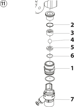
- Remove the pusher stem clip and slide the pusher stem housing (7) from the inlet valve housing (1).
- Unscrew the inlet valve housing (Fig. 11, Item 1) from the pump manifold.
![]()
- Remove the lower seal (2), lower ball guide (3), inlet valve ball (4), inlet valve seat (5) and O-ring (6).
- Clean all the parts with the corresponding cleaning agent. Check the inlet valve housing (1), inlet valve seat (5) and inlet valve ball (4) for wear and replace the parts if necessary. If the worn inlet valve seat (5) is unused on one side, install it the other way round.
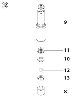
- Unscrew outlet valve housing (Fig. 12, Item 8) from the piston (9) with adjusting wrench.
![]()
- Remove the upper ball cage (11), crush washer (10), outlet valve ball (12), and outlet valve seat (13).
- Clean all the parts with the corresponding cleaning agent. Check outlet valve housing (8), outlet valve seat (13), outlet valve ball (12), crush washer (10), and upper ball cage (11) for wear and replace parts if necessary. If the worn outlet valve seat (13) is unused on one side, install it the other way round.
- Carry out installation in the reverse order. Lubricate O-ring (Fig. 11, Item 6) with machine grease and ensure proper seating in the inlet valve housing (Fig. 11, Item 1).
SELECTION OF TIP
To achieve faultless and rational working, the selection of the tip is of the greatest importance.
In many cases the correct tip can only be determined by means of a spraying test.
SOME RULES FOR THIS:
The spray jet must be even.
If streaks appear in the spray jet the spraying pressure is either too low or the viscosity of the coating material to high.
REMEDY: Increase pressure or dilute coating material. Each pump conveys a certain quantity in proportion to the size of the tip:
The following principle is valid:
large tip = low pressure
small tip = high pressure
There is a large range of tips with various spraying angles.
SERVICING AND CLEANING OF AIRLESS HARD-METAL TIPS
STANDARD TIPS
If a different tip type has been fitted, then clean it according to manufacturer's instructions.
The tip has a bore processed with the greatest precision. Careful handling is necessary to achieve long durability. Do not forget the fact that the hard-metal insert is brittle! Never throw the tip or handle with sharp metal objects.
The following points must be observed to keep the tip clean and ready for use:
- Turn the relief valve handle fully counterclockwise (
![]() Circulation).
Circulation). - Remove the tip from the spray gun.
- Place tip in an appropriate cleaning agent until all coating material residue is dissolved.
- If there is high-pressure air available, blow out tip.
- Remove any residue by means of a sharp wooden rod (toothpick).
- Check the tip with the help of a magnifying glass and, if necessary, repeat points 3 to 5.
TESTING OF THE UNIT
For safety reasons, we would recommend having the device checked by an expert as required but at least every 12 months to ensure that it can continue to operate safely. In the case of unused devices, the check can be postponed until they are next started up.
All (potentially deviating) national inspection and maintenance regulations must also be observed.
If you have any questions, please contact the customer service team at Titan.
SPARE PARTS DIAGRAM
MAIN ASSEMBLY

| # | Impact 440 | Description |
| 1 | 0508 604 | O-ring |
| 2 | 0508 749 | Bearing spring |
| 3 | 0508 603 | Bearing ring |
| 4 | 0508 748 | Filter |
| 5 | 0508 602 | Conical spring |
| 6 | 0508 601 | Filter housing |
| 7 | 0509 218 | Screw (4) |
| 8 | 0290 278 | Face plate / oiler assembly |
| 9 | 0508 239 | Manometer |
| 10 | 0509 873 | Fitting |
| 11 | 700-258 | Relief valve w/ handle |
| 12 | 0551 262 | Upper cage |
| 13 | 0551 263 | Crush washer |
| 14 | 50164 | Outlet valve ball |
| 15 | 0551 620 | Outlet valve seat |
| 16 | 13481 | Outlet valve retainer |
| 17 | 0509 583 | Inlet valve ball |
| 18 | 0551 534 | Inlet valve seat |
| 19 | 0509 582 | O-ring, PTFE |
| 20 | 0290 205 | Pusher assembly |
STAND ASSEMBLY

| # | Impact 440 | Description |
| 1 | 9805 367 | Screw (3) |
| 2 | 0290 215 | Drip cup |
| 3 | 0290 211 | Leg, right |
| 4 | 0294 635 | Plug |
| 5 | 0290 214 | Foot |
| 6 | 0508 660 | Screw (2) |
| 7 | 0294 635 | Plug |
| 8 | 0290 219 | Cord holder |
| 9 | 0290 214 | Foot |
| 10 | 0290 210 | Leg, left |
| 0290 203 | Left leg assembly (includes items 6-10) | |
| 0290 204 | Right leg assembly (includes items 1-5) |
SUCTION SYSTEM FOR STAND
| Pos. | Impact 440 | Description |
| 1 | 0558672A | Siphon tube assembly (includes items 1-9) |
| 2 | 0558659A | Return tube |
| 3 | 0279459 | Clip |
| 4 | 0295565 | Inlet screen |
| 5 | 9871105 | O-ring (2) |
| 704-109 | O-ring (for hot solvents, optional) (2) | |
| 6 | 9822526 | Retaining clip |
| 7 | 9850638 | Tie wrap |
| 8 | 0327226 | Return tube clamp |
| 9 | 193-200 | Return tube fitting |
ACCESSORIES
| PART NO. | DESCRIPTION |
| SPRAY GUNS | |
| 0538005 | RX-80 with TR-1 517 Tip |
| 0538020 | RX-Pro with TR-1 517 Tip |
| 0550060 | S-3 spray gun |
| 0550070 | S-5 spray gun |
| 0289013 | M-4 spray gun |
| 0538217 | RX-Pro, small grip |
| 0538218 | RX-Pro, medium grip |
| 0538219 | RX-Pro, large grip |
| MULTI-SPRAY GUN MANIFOLDS | |
| 975-212 | 2-Gun Manifold with Ball Valves, 1/4" |
| 975-213 | 3-Gun Manifold with Ball Valves, 1/4" |
| 975-312 | 2-Gun Manifold with Ball Valves, 3/8" |
| 975-313 | 3-Gun Manifold with Ball Valves, 3/8" |
| SPRAY TIPS AND ACCESSORIES | |
| 662-XXX | SC-6+ Tip* |
| 695-XXX | TR-1 Tip* |
| 692-XXX | TR-2 Tip* |
| 671-XXX | Fine Finish Tip* |
| 0289228 | No Build Tip Guard |
| 651-139 | Tip Swivel |
| 661-020 | Tip seat and seal kit (5 pack) |
| FILTERS | |
| 0089957 | Coarse Mesh Filter (Green) |
| 0089958 | Medium Mesh Filter (White) |
| 0089959 | Fine Mesh Filter (Yellow) |
| 0089960 | Extra Fine Mesh Filter (Red) |
| 930-004 | Paint Filter Element, 0 Mesh (for mastics) |
| 930-005 | Paint Filter Element, 5 Mesh (for multicolors and heavy materials) |
| 930-006 | Paint Filter Element, 50 Mesh (for latex and normal architectural materials) |
| 930-007 | Paint Filter Elements, 100 Mesh (for stains, lacquers and fine materials) |
| EXTENSIONS | |
| 651-070 | 6" Tip Extension |
| 651-071 | 12" Tip Extension |
| 651-072 | 18" Tip Extension |
| 651-073 | 24" Tip Extension |
| 310-390 | 3' Extension Pole |
| 310-391 | 6' Extension Pole |
| AIRLESS HOSE AND ACCESSORIES | |
| 316-505 | 1/4" x 50' Airless Hose |
| 0291006 | 3/8" x 50' Airless Hose |
| 316-506 | 3/16" x 5' Whip Hose |
| 490-012 | 1/4" x 1/4" hose connector |
| 0508239 | High Pressure Fluid Gauge |
| 310-150 | 9" Pressure Roller Kit |
| 0521012 | Non-Spit Valve |
| LUBRICANTS AND CLEANERS | |
| 314-482 | Liquid Shield™ 1 Quart |
| 314-480 | Piston Lube™, 8 oz |
| 700-926 | Piston Lube™, 1 Quart |
| 0297055 | Pump Shield™, 12 oz. |
| 0508071 | Paint Mate 1 Quart |
| * | Go to www.titantool.com for tip sizes |
GENERAL SAFETY INSTRUCTIONS

 Read all safety information, instructions, illustrations and technical data provided with this power tool. Failure to observe the following instructions may cause electric shock, fire and/or severe injuries. Keep all safety information and instructions for future reference. The term "power tool" used in this safety information refers to mainsoperated power tools (with power cable) and to battery-powered power tools (without power cable).
- Safety at the workplace
- Keep your workplace clean and well lit. Disorder or unlit workplaces may result in accidents.
- Do not work with the power tool in potentially explosive environments where there are flammable fluids, gases or dust. Power tools generate sparks that can ignite the dust or vapors.
- Keep children and other persons away when using the power tool. If distracted, you may lose control of the power tool.
- Electrical Safety
- The connection plug of the power tool must fit in the socket. The plug may not be modified in any form. Verwenden Sie keine Adapterstecker gemeinsam mit schutzgeerdeten Elektrowerkzeugen. Unmodified plugs and suitable sockets reduce the risk of an electric shock.
- Avoid physical contact with earthed surfaces such as pipes, heating elements, stoves and refrigerators. The risk through electric shock increases if your body is earthed.
- Keep power tools away from rain or moisture. Water penetrating into a power tool increases the risk of an electric shock.
- Do not misuse the power cord to carry the power tool, hang up the power tool or pull the plug out of the socket. Keep the power cord away from heat, oil, sharp edges or moving parts. Damaged or entangled power cords increase the risk of an electric shock.
- If the power tool must be used in a moist environment, use a ground fault circuit interrupter. Using a residual current operated circuit-breaker avoids the risk of electric shock.
- Safety of Persons
- Be attentive. Pay attention to what you are doing and work sensibly with a power tool. Do not use the power tool if you are tired or under the influence of drugs, alcohol or medication. One moment of carelessness when using the power tool may cause serious injuries.
- Wear personal safety equipment and always wear safety goggles Wearing personal protective equipment, such as dust mask, non-slip safety shoes, safety helm or ear protection, depending on the type of power tools, reduces the risk of injury.
- Avoid accidental starting-up. Make sure that the power tool is switched off before you connect it to the power tool and/or battery, pick it up or carry it. Accidents may happen if you have your finger on the switch while carrying the power tool or if the device is switched on when you connect it to the power supply.
- Remove setting tools or wrenches before switching on the power tool. A tool or key in a rotating part of the power tool can cause injuries.
- Avoid an unnatural posture. Ensure that you are standing securely and have your balance at all times. This allows you can better control the power tool in unexpected situations.
- Wear suitable clothing. Do not wear wide clothing or jewellery. Keep your hair, clothes and gloves away from moving parts. Loose clothing, jewellery or long hair can be caught in moving parts.
- Do not lull yourself into a false sense of security and do not think yourself above the safety rules for electric tools, even if you are familiar with the electric tool following extensive practical experience.Careless use can lead to serious injuries in fractions of a second.
- Usage and treatment of the electric tool
- Do not overload the power tool. Use the power tool designed for the work that you are doing. You work better and safer in the specified performance range if you use the suitable power tool.
- Do not use power tools whose switch is defective. A power tool that cannot be switched on or off is dangerous and has to be repaired.
- Disconnect the plug from the socket and/or take out a removable battery before you make device adjustments, change accessories or put the power tool away. This precautionary measure prevents the power tool from starting unintentionally.
- Store unused power tools so that they are inaccessible to children. Do not let persons use the tool who are not familiar with it or who have not read these instructions. Power tools are dangerous when they are used by inexperienced persons.
- Maintain the power tool and insertion tools with care. Check whether moving device parts are working flawlessly and are not jamming, whether parts are broken or damaged so that as to impair the function of the power tool. Have damaged parts repaired before using the power tool. Many accidents have their origin in power tools that have been maintained badly.
- Use the power tool, accessories, insert tools, etc. in accordance with these instructions and in a fashion specified for this special tool type. Take the working conditions and the activity to be carried out into consideration. The use of power tools for purposes other than the intended ones can lead to dangerous situations.
- Keep the handles and grip surfaces dry, clean and free of oil and grease. Slippery handles and grip surfaces hamper safe operation and control of the electric tool in unforeseen situations.
- Service
- Only have your power tool repaired by a qualified specialist and only use original spare parts. This ensures that the tool safety is maintained.
- If the supply cord is damaged, it must be replaced by the manufacturer or it's service agent or a similarly qualified person in order to avoid a safety hazard.
SAFETY REGULATIONS FOR AIRLESS SPRAYING
All local safety regulations in force must be observed. The following safety regulations are to be observed in order to ensure safe handling of the Airless high-pressure spraying unit.
FLASH POINT

Only spray coating materials with a flash point of 21°C or higher.
The flash point is the lowest temperature at which vapors develop from the coating material. These vapors are sufficient to form an inflammable mixture over the air above the coating material.
EXPLOSION PROTECTION
Do not use the unit in work places which are covered by the explosion protection regulations. The unit is not designed to be explosion protected. Do not operate the device in explosive areas (zone 0, 1 and 2). Explosive areas are, for example, places where paints are stored and locations in direct proximity to the object being sprayed. Keep the device at least 3 m from the object you are spraying.
DANGER OF EXPLOSION AND FIRE FROM SOURCES OF IGNITION DURING SPRAYING WORK
There must be no sources of ignition such as, for example, open fires, lit cigarettes, cigars or tobacco pipes, sparks, glowing wires, hot surfaces, etc. in the vicinity.
DANGER OF INJURY FROM THE SPRAY JET

Attention, danger of injury by injection! Never point the spray gun at yourself, other persons or animals.
Only use the spray gun with spray jet touch protection.
The spray jet must not come into contact with any part of the body.
In working with Airless spray guns, the high spray pressures arising can cause very dangerous injuries. If contact is made with the spray jet, coating material can be injected into the skin. Do not treat a spray injury as a harmless cut. In case of injury to the skin by coating material or solvents, consult a doctor for quick and correct treatment. Inform the doctor about the coating material or solvent used.
SECURE SPRAY GUN AGAINST UNINTENDED OPERATION
Always secure the spray gun when mounting or dismounting the tip and in case of interruption to work.
RECOIL OF SPRAY GUN
When using a high operating pressure, pulling the trigger guard can effect a recoil force up to 15 N. If you are not prepared for this, your hand can be thrust backwards or your balance lost. This can lead to injury.
BREATHING EQUIPMENT AS PROTECTION AGAINST SOLVENT VAPORS
Wear breathing equipment during spraying work.
PREVENTION OF OCCUPATIONAL ILLNESSES
Wear safety goggles.
Wear hearing protection.
Protective clothing, gloves and possibly skin protection cream are necessary for the protection of the skin.
Observe the regulations of the manufacturer concerning coating materials, solvents and cleaning agents in preparation, processing and cleaning units.
MAX. OPERATING PRESSURE
The permissible operating pressure for the spray gun, spray gun accessories, unit accessories and high-pressure hose must not fall short of the maximum operating pressure of 22.1 MPa (221 bar).
HIGH-PRESSURE HOSE
Attention, danger of injury by injection!
Wear and tear and kinks as well as usage that is not appropriate to the purpose of the device can cause leakages to form in the high-pressure hose. Liquid can be injected into the skin through a leakage.
- Ÿ High-pressure hoses must be checked thoroughly before they are used.
- Ÿ Replace any damaged high-pressure hose immediately. Ÿ Never repair defective high-pressure hoses yourself!
- Ÿ Avoid sharp bends and folds: the smallest bending radius is about 20 cm.
- Ÿ Do not drive over the high-pressure hose. Protect against sharp objects and edges.
- Ÿ Never pull on the high-pressure hose to move the device.
- Ÿ Do not twist the high-pressure hose.
- Ÿ Do not put the high-pressure hose into solvents. Use only a wet cloth to wipe down the outside of the hose.
- Ÿ Lay the high-pressure hose in such a way as to ensure that it cannot be tripped over.
Only use Titan original-high-pressure hoses in order to ensure functionality, safety and durability.
ELECTROSTATIC CHARGING (FORMATION OF SPARKS OR FLAMES)

Electrostatic charging of the unit may occur during spraying due to the flow speed of the coating material. These can cause sparks and flames upon discharge. The unit must therefore always be earthed via the electrical system. The unit must be connected to an appropriately-grounded safety outlet.
An electrostatic charging of spray guns and the high-pressure hose is discharged through the high-pressure hose. For this reason the electric resistance between the connections of the high-pressure hose must be equal to or lower than 1 MΩ.
USE OF UNITS ON BUILDING SITES AND WORKSHOPS
The unit may only be connected to the mains network via a special feeding point with a residual-current device with INF ≤ 30 mA. An upstream circuit breaker (fuse) with 16 A (B or C characteristics) is required.
VENTILATION WHEN SPRAYING IN ROOMS
Adequate ventilation to ensure removal of the solvent vapors has to be ensured.
SUCTION INSTALLATIONS
The are to be provided by the unit user in accordance with the corresponding local regulations.
EARTHING OF THE OBJECT
The object to be coated must be earthed. (Building walls are usually earthed naturally)
COATING MATERIAL
Caution against dangers that can arise from the sprayed substance and observe the text and information on the containers or the specifications given by the substance manufacturer.
Do not spray any liquid of unknown hazard potential.
CLEANING THE UNIT
When cleaning the gun, only rinse when the nozzle is removed and rinse at low pressure.
| | When cleaning the unit with solvents, the solvent should never be sprayed or pumped back into a container with a small opening (bunghole). An explosive gas/air mixture can arise. Only use an earthed container made from metal. To earth the gun, hold it firmly on the edge of the container. | |
| | Danger of short-circuits caused by water ingression! Never spray down the unit with high-pressure or high-pressure steam cleaners. | |
WORK OR REPAIRS AT THE ELECTRICAL EQUIPMENT
These may only be carried out by a skilled electrician. No liability is assumed for incorrect installation. Unplug the power plug from the outlet before carrying out any repair work.
MAINTENANCE WORK AND BREAKS
Before carrying out any work on the device and during any work break, release the pressure in the spray gun and high-pressure hose. Secure the spray gun's trigger guard and switch off the device.
SETUP ON AN UNEVEN SURFACE
The front end must always point downwards in order to avoid sliding away.
If possible do not use the unit on an inclined surface since the unit tends to wander through the resulting vibrations.
OSCILLATION LEVEL
The specified oscillation level has been measured according to a standard test procedure and can be used to compare against electric tools. The oscillation level is also for determining an initial assessment of the vibrational strain.
Attention! The vibration emission value can differ from the specified value when the electric tool is actually in use, depending on how the electric tool is being used. It is necessary to specify safety measures to protect the operating personnel. These measures are based on an estimated shutdown during the actual conditions of use (all parts of the operating cycle are taken into consideration here, for example periods when the electric tool is switched off, and, when it is switched on but running without any load).
UNITED STATES SALES & SERVICE
WEB: www.titantool.com
PHONE: 1-800-526-5362
1770 Fernbrook Lane
Minneapolis, MN 55447
INTERNATIONAL
WEB: www.titantool-international.com
Documents / Resources
References
![www.titantool.com]() Professional Paint Sprayers | Industrial Paint Sprayer | Titan Tool
Professional Paint Sprayers | Industrial Paint Sprayer | Titan Tool![www.titantool-international.com]() Professional Paint Sprayers | Industrial Paint Sprayer | Titan Tool
Professional Paint Sprayers | Industrial Paint Sprayer | Titan Tool
Download manual
Here you can download full pdf version of manual, it may contain additional safety instructions, warranty information, FCC rules, etc.
Advertisement


Need help?
Do you have a question about the IMPACT 440 and is the answer not in the manual?
Questions and answers