Lippert Level-Up Manual
- Manual (10 pages) ,
- Instruction manual (12 pages) ,
- Owner's manual (20 pages)
Advertisement
- 1 System
- 2 Maintenance
- 3 Controls
- 4 Error Mode
-
5
Operation
- 5.1 Selecting A Site
- 5.2 Automatic Leveling Procedure
- 5.3 Automatic Leveling Descriptive Logic
- 5.4 Manual Leveling Procedure
- 5.5 Jack Retract Procedures
- 5.6 Remote Leveling Operation
- 5.7 Manual Override - Jacks
- 5.8 Manual Override - Power System
- 5.9 Automatic Safety Shutoff
- 5.10 Drive Away Protection System
- 5.11 Jacks Up Verification
- 6 Wiring Diagram
- 7 Plumbing Diagram
- 8 Bill of Materials
- 9 Troubleshooting Guide
- 10 Documents / Resources
System

Failure to act in accordance with the following may result in serious personal injury or death.
The use of the Lippert Level-Up Motorhome Leveling System for Winnebago Industries to support the coach for any reason other than which it is intended is prohibited by Lippert's Limited Warranty. The Lippert Level-Up Motorhome Leveling System for Winnebago Industries is designed as a leveling system only and should not be used to provide service for any reason under the coach, such as changing tires or servicing the leveling system.
Lippert Components, Inc. recommends that a trained professional be employed to change the tires on the coach. Any attempts to change tires or perform other service while coach is supported by the Lippert Level-Up Motorhome Leveling System for Winnebago Industries could result in damage to the motorhome and/or cause serious injury or death.
- Be sure to park the coach on solid, level ground.
- Clear all jack landing locations of debris and obstructions. Locations should also be free of depressions.
- When parking the coach on extremely soft surfaces, utilize load distribution pads under each jack.
- People and pets should be clear of coach while operating leveling system.
- Be sure to keep hands and other body parts clear of fluid leaks. Oil leaks in the Lippert Level-Up Motorhome Leveling System for Winnebago Industries may be under high pressure and can cause serious skin penetrating injuries.
- Never lift the coach completely off the ground. Lifting the coach so the wheels are not touching the ground will create an unstable and unsafe condition.
Prior to Operation
The leveling system should only be operated under the following conditions:
- The coach is parked on a reasonably level surface.
- The coach "PARKING BRAKE" is engaged.
- The coach transmission should be in the neutral or park position.
- Be sure all persons, pets and property are clear of the coach while Lippert Level-Up Motorhome Leveling System for Winnebago Industries is in operation.

After starting the automatic leveling cycle it is very important that you do not move around in the coach until the unit is level and the green LED light illuminates in the center of the touch pad. Failure to remain still during the leveling cycle could have an effect on the performance of the leveling system.
System Description
Please read and study the operating manual before operating the leveling system.
The Lippert Level-Up Motorhome Leveling System for Winnebago Industries is an electric/hydraulic system. A 12V DC electric motor drives a hydraulic pump that moves fluid through a system of hoses, fittings and jacks to level and stabilize the coach.
Mechanical portions of the Lippert Level-Up Motorhome Leveling System for Winnebago Industries are replaceable. Contact Lippert Components, Inc. to obtain replacement parts. See the Bill Of Materials list.
Component Description
- Jacks
- Rated at a lifting capacity for your coach.
- 9" diameter (63.5 square inch) foot pad on a ball swivel for maximum surface contact on all surfaces.
- 12" diameter - (113 square inch) foot pad also available.
- Powered from a 12V DC Motor/Pump assembly.
- Motor/Pump Assembly
- 12V DC Motor
- Hydraulic oil reservoir tank
- Control valve manifold
- Solenoid valves
- System Controls
- Controlled electronically from the driver's seat of the coach.
- Touch pad is mounted in the dash or side console.
- Touch pad can be operated in manual mode or fully automatic mode.
Maintenance
Fluid Recommendation
The Lippert Level-Up Motorhome Leveling System for Winnebago Industries is pre-filled, primed and ready to operate direct from Winnebago Industries:
PetroBlend (Mason City, IA), PHO 0022S (group 3 base blend).
NOTE: In colder temperatures (less than 10°F) the jacks may extend and retract slowly due to the fluid's molecular nature. For cold weather operation, fluid specially formulated for low temperatures may be desirable. Contact your manufacturer for recommended fluid.
Preventative Maintenance
- Check fluid in reservoir every 12 months. If fluid is a clear, red color, do not change. If fluid is milky, pink and murky, and not clear red in color, drain reservoir and add new fluid.
NOTE: Check fluid only when all jacks are fully retracted.
NOTE: When checking fluid level, fill to within ¼ to ½ inch of fill spout. - Inspect and clean all Power Unit electrical connections every 12 months. If corrosion is evident, spray unit with lubricant.
- Remove dirt and road debris from jacks as needed.
![]()
The coach should be supported at both front and rear axles with jack stands before working underneath. Failure to do so may result in death or personal injury. - If jacks are down for extended periods, it is recommended to spray exposed leveling jack rods with a silicone lubricant every three months for protection. If the coach is located in a salty environment, it is recommended to spray the rods every four to six weeks. NOTE: OEM to install attachment brackets for leveling jacks.

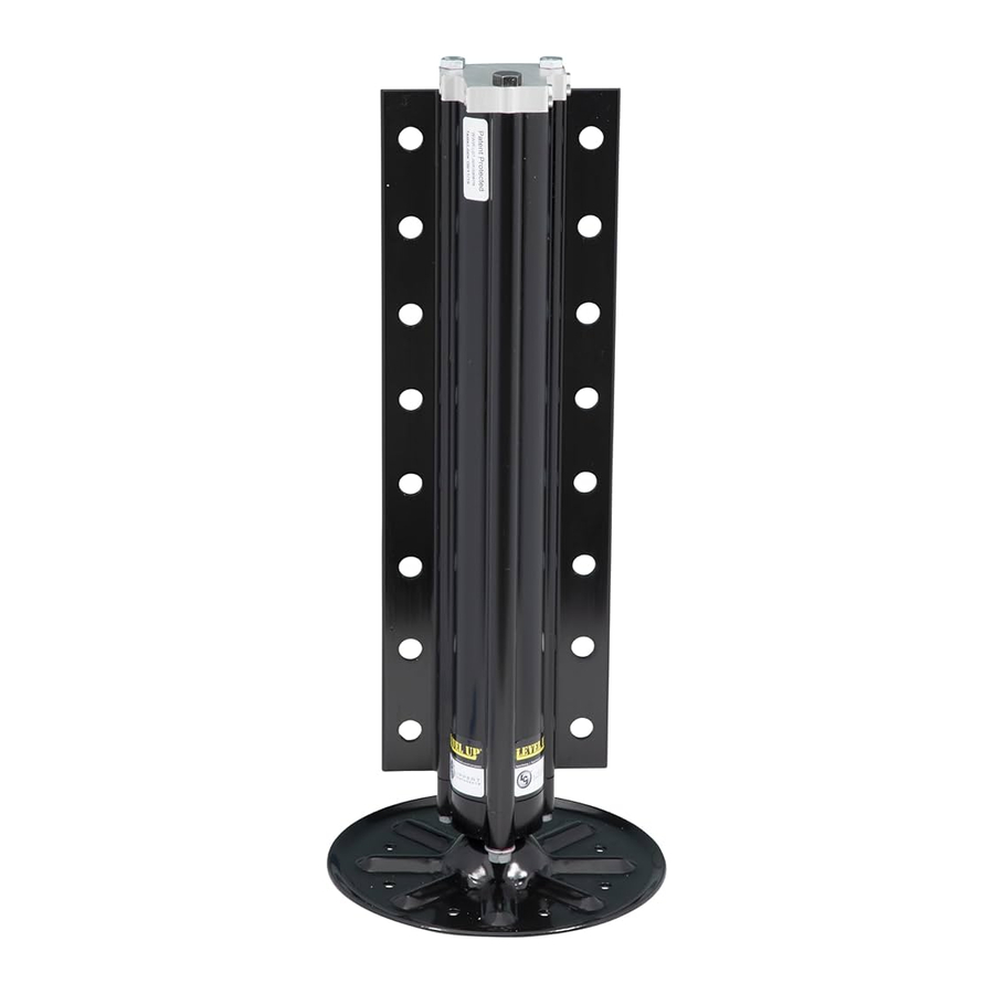
Fig. 1
CAPACITY - 8,000 lb.
STROKE - 15.00 in.
BORE - 2.00 in.
HEIGHT - 21.1875 in.
ROD DIA. - 1.50 in.
9" FOOTPAD-STANDARD
12" FOOTPAD-OPTION - Part# - 117238

Fig. 2
CAPACITY - 14,000 lb.
STROKE - 15.13 in.
BORE - 2.50 in.
HEIGHT - 21.625 in.
ROD DIA. - 1.875 in.
9" FOOTPAD-STANDARD
12" FOOTPAD-OPTION - Part# - 117238

Fig. 3
CAPACITY - 20,000 lb.
STROKE - 16.00 in.
BORE - 3.00 in.
HEIGHT - 23.125 in.
ROD DIA. - 2.25 in.
12" FOOTPAD-STANDARD
Fitting Orientation
NOTE: Fittings - High pressure O-Ring Face - Size 4
NOTE: Hose - ¼ in. I.D. 3000 psi - W.P. Rated

| Callout | Part # | Description |
| A | 177094 / 174184 | Valve/Coil - Rear Jacks |
| B | 142927 | Pressure Switch |
| C | -- | Filler Vent |
| D | 156846 / 141109 (Straight) | Extend Fittings NOTE: Fittings are labeled w/ port assignments found stamped into the manifold. |
| E | 140457/320521 (Elbow) | Quick Disconnect for Flush & Fill |
| F | 156846 / 143108 | Return Fittings |
| H | 177094/174184 | Valve/Coil - Front Jacks |
Controls

| Callout | Description |
| A | Up Arrow - Scrolls up through the menu on LCD. |
| B | Down Arrow - Scrolls down through the menu on LCD. |
| C | Enter - Activates modes and procedures indicated on LCD. |
| D | Retract - Places leveling system into retract mode. - Manual mode ONLY |
| E | LCD Display - Displays procedures and results. |
| F | Auto Level - Places leveling system into auto level mode. |
| G | Front Jack Button - Activates both front jacks in manual mode. |
| H | Left Jack Button - Activates both left jacks in manual mode. |
| I | Right Jack Button - Activates both right jacks in manual mode. |
| J | Rear Jack Button - Activates both rear jacks in manual mode. |
| K | Power Button - Turns leveling system on and off. |
Features
- Automatic extension of jacks from full retract position (with automatic ground detection).
- Automatic leveling of jacks.
- Manual leveling of jacks
- Automatic retraction of jacks (with automatic full retract detection).
- Air bag suspension features (configurable on/off).
- Jacks Up Verification (jacks not retracted and park brake disengaged).
- Automatic jack error detection and error mode.
- Configurations mode for Leveling Zero Point.
- Remote operation.
System Wiring Requirements
- Battery power (2 ga. SAE J1127. Type SGX).
- Battery ground (2 ga. SAE J1127. Type SGX).
- Logic power (switched via ignition).
- Power brake signal (open=park brake disengaged, GND=park brake engaged).
- 4-wire harness connecting Controller to Touch Pad.
- Jacks status input - Switched to GND.
- Jacks not all up – switch closed to ground.
- Jacks all up – switch open.
Air and Auxiliary Features (When Applicable)
System has the option to control external Air and Auxiliary features.
When enabled, the feature works according to the following logic:
- Air bag pressure automatically lowers when starting the auto or manual level sequence to maximize lift of jacks.
- Air bags automatically fill during any retract sequence or when the park brake is disengaged.
The Manual Air Bag Dump/Fill functions as follows:
- Set park brake.
- Scroll up twice to "MANUAL AIR CONTROL".
- Press enter.
- Press REAR button (Fig. 5I) to dump, FRONT button (Fig. 5H) to fill.
Level Zero Point Calibration
Before auto-leveling features are available, the Level Zero Point must be set. This is the point to which the system will return when an auto leveling cycle is initiated.
To set the Zero Point (controller module must be fully secured in production-intent location), first run a manual leveling sequence to get the vehicle to the desired level point. Then activate the Level Zero Point configuration mode.
This mode is enabled by performing the following sequence:
- Turn panel off.
- Perform the following:
- Press the "FRONT" button (Fig. 5H) 5 times.
- Press the "REAR" button (Fig. 5I) 5 times.
- At this point, an alarm will sound and the display will read "**ZERO POINT CALIBRATION**" ENTER to Set, POWER to Exit."
- Press ENTER (Fig. 5C) to set the Zero Point.
- Screen will then display "PLEASE WAIT".
- Alarm will sound and the screen will display "ZERO POINT SUCCESSFUL".
- Control will then turn "OFF".
For DIESEL UNITS with Air Bag Suspensions ONLY:
NOTE: The leveling control will automatically program for air bag control. The option will not be present if no dump valve coil resistance is detected.
Error Mode
- If an error occurs before or during operation, the error will be displayed in the LCD and an alarm will sound. To reset common ERROR displays, press ENTER (Fig. 5C).
NOTE: To reset "Return for Service" errors, press "ENTER" (Fig. 5C) and "RETRACT" (Fig. 5D) simultaneously. - All normal functions will be disabled when the system is in error mode.
- Auto level can only commence if running voltage is 12.75V DC or above.
- Auto level operation will halt if running voltage drops to 9.5V DC.
- Manual level operation can be performed at all running voltages above 9.5V DC.
Excess Slope
- The control will not operate at extreme slopes, i.e. 3.5° fore and aft and 3.5° side to side.
- If the coach indicates "EXCESS ANGLE" or "OUT OF STROKE " during an auto level cycle, move the coach to a more level spot.
| LCD Display | What is Happening? | What Should Be Done? |
| ****ERROR**** Excess Angle | Coach not parked on level ground. Zero point incorrectly calibrated. | Move coach to level ground prior to starting auto level sequence. Recalibrate Zero Point. |
| ****ERROR**** External Sensor | Rear sensor shorted out or disconnected. | Check wire connection or replace sensor. |
| Out of Stroke | Jack has insufficient length to complete the leveling procedure. | Check the disposition of the jack. |
| Low Voltage | Battery voltage dropped below 9.5 VDC during operation. | Turn engine on, check battery voltage under load. |
| Function Aborted | A button was pressed on touch pad during Auto Level operation. | Hit enter to acknowledge. Restart procedure. |
| Unable to Finish Leveling | Excessive movement inside coach during auto level sequence. | Discontinue movement inside coach during auto level sequence. |
| Engage Park Brake | Parking brake not set prior to starting auto level sequence. | Set parking brake prior to starting auto level sequence. |
| Comm Error Check Wiring NOTE: Screen will not back light. | Wiring connections loose or faulty between touch pad and controller. | Check connections, replace communication harness if necessary. |
| ****ERROR**** Retract Timeout Return Levelers for Service | Pressure switch did not sense retract pressure and pump timed out. Leaking hose or fitting. | Return levelers for service. Check for leaks, repair if necessary. Press enter and retract to clear error. |
| Excessive Angle | Occurs only in manual mode when the angle of the unit is too severe. | Use the manual functions to return coach to a more level condition. |
User Alarm Mode
If the alarm system detects that the park brake has been disengaged while at least one jack is not fully retracted and the sensor value changes in any axis more than a predefined amount, the panel will signal this error to the user. The system performs an automatic retract.
No other features are available in this mode.
Miscellaneous
- The leveling system will automatically shut off after being idle for 4 minutes.
- A "Re-level" feature is programmed into the Rev G controller. If the jacks are extended and the user presses Auto Level again the system will re-level from that point. The system will not retract before performing the Re-Level.
- System will refuse any operation when a low voltage condition is present.
- System will automatically alarm and retract if park brake is disengaged and jacks are not retracted with any change in sensor readings. In alarm mode, the only available feature is to retract all jacks.
Low Voltage Signal
- The vehicle requires 12.75V DC to operate in the AUTO mode. If the voltage is too low, the screen will display "LOW VOLTAGE".
- Minimum Voltage - If voltage drops below 9.5V DC during AUTO or MANUAL operation, "LOW VOLTAGE" will appear in the screen and the system will cease operating.
NOTE: Coach will operate in manual mode between 9.5V DC and 12.75V DC.
Operation
Selecting A Site
When the coach is parked on an excessive slope the leveling requirements may exceed the jack lift stroke capability. If the coach is parked on an excessive slope, the coach should be moved to a more level surface before the leveling system is deployed.
"EXCESS ANGLE" will appear on the LCD screen if the coach is 3.5° out of level front to rear or side to side. See error code chart.
Automatic Leveling Procedure
NOTE: Refer to Component Description (Fig. 5) for questions regarding location and functions of the Lippert Level-Up Motorhome Leveling System for Winnebago Industries system.
NOTE: Coach must be running and parking brake must be engaged for Lippert Level-Up Motorhome Leveling System for Winnebago Industries to operate.
- Press "ON/OFF" button to turn system "ON" (Fig. 5K).
- Press "AUTO LEVEL" button (Fig. 5F). LCD Screen will display "REMAIN STILL".
- The coach will level automatically and indicate "Auto Level - SUCCESS!" in LCD display (Fig. 5E).
NOTE: Display will then read "LEVEL - Jacks: Down". Do not press any buttons until this message appears or a "FUNCTION ABORTED" error will be displayed.
NOTE: Always check to make sure all jacks are fully retracted before travel.
Automatic Leveling Descriptive Logic
Grounding: Steps 1 - 7 describe the process of how the AUTO LEVEL LOGIC extends the jacks to the ground:
- Depending on which end of the coach is lowest to the ground the level sensor in the controller will activate the jacks, one at a time on the lowest end first, either front or rear.
- Ground lowest side jack first; i.e., front passenger side.
- Ground remaining side jack next; i.e., front driver side.
- Together, both jacks will lift lowest end until level; i.e., front of coach will lift briefly until the coach is level.
- The system will then ground remaining jacks, one at a time; i.e., rear jacks.
- Ground lowest side jack first; i.e., rear passenger side.
- Ground remaining side jack next; i.e., rear driver side.
Leveling: Steps 8- 11 describe the process of how the AUTO LEVEL LOGIC levels the coach once the jacks have been grounded. This process may repeat several times until level. - Fore/aft
- Side/side
- Individual
- Minor adjustments to limit/prevent twist
After starting the automatic leveling cycle it is very important that you do not move around in the coach until the unit is level and the green LED light illuminates in the center of the touch pad. Failure to remain still during the leveling cycle could have an effect on the performance of the leveling system.
Manual Leveling Procedure
NOTE: When leveling your coach the coach should be leveled from front to rear first. When the coach is level from front to rear, then level the coach from left to right.
NOTE: Coach requires 12.75 VDC to commence auto leveling function. If voltage at the power unit is not 12.75 VDC, run the engine.
- Apply parking brake.
- Turn ignition "On".
- Press "ON/OFF" button (Fig. 5K) to turn system "ON".
- Press "UP" or "DOWN" button (Fig. 5A/B) to scroll through features to "MANUAL MODE" in display.
- Press "ENTER" (Fig. 5C).
- Press "FRONT" button (Fig. 5H) to extend front jacks to the ground; Press "REAR" button (Fig. 5I) to run rear jacks to ground and level the coach front to back.
- Press appropriate "LEFT" or "RIGHT" button to level the coach from side to side. Red flashing lights next to the buttons on touch pad will indicate which side(s) of the coach needs to be raised to achieve level condition.
NOTE: Jacks always work in pairs, i.e., "FRONT" button operates both front jacks, etc.
NOTE: The right and left jacks are used to level the coach side to side. Pressing the LEFT button (Fig. 5G) on the control panel will extend both left jacks. Pressing the RIGHT button (Fig. 5J) on the control panel will extend both right jacks. Jacks always work in pairs, both front jacks; both right side jacks, etc. - Repeat steps 2 through 7 as needed.
- Turn power off to leveling system by Pressing ON/OFF button (Fig. 5K).
- Visually inspect all jacks to ensure all footpads are touching the ground. Should one of the rear jack footpads not be touching the ground, press the corresponding LEFT or RIGHT arrow buttons to lower the non-compliant jack to the ground.
NEVER LIFT ALL THE WHEELS OFF THE GROUND TO LEVEL THE COACH!
Lifting all the wheels off the ground may result in death or serious personal injury.
Jack Retract Procedures
- Energize the system by pressing ON/OFF button (Fig. 5K) on control panel. The LCD screen will display READY Jacks: Down".
- Press "DOWN" button (Fig. 5B) to display "Auto Retract All" on the screen.
- Press "ENTER" (Fig. 5C) to begin.
NOTE: If the need to stop the jacks from retracting arises, turn the system off and back on again by pressing the "ON/OFF" button (Fig. 5K) twice. The coach can then be manually leveled by following steps 1-9 in the MANUAL LEVELING PROCEDURE section. Press "ENTER" to acknowledge. - The jacks will retract and shut off automatically; the display will read "READY - Jacks: Up". Press the "ON/OFF" button (Fig. 5K) on the Control Panel to de-energize the system. After a brief visual inspection around the coach to verify the jacks are fully retracted, you may proceed to travel.
- To retract in the MANUAL mode, press the "RETRACT" button (Fig. 5D) until it lights. By pressing any of the JACK buttons, the jacks will retract in pairs, i.e. "FRONT" button, both front jacks will retract, etc.
NOTE: Prior to allowing manual retract functions, the air bags will fill. There will be a 22 second countdown on the LCD display while the air bag fill occurs. - "AUTO RETRACT" can also be commenced by pressing and holding the "RETRACT" button (Fig. 5D) for 1 second.
NOTE: Always check to make sure all jacks are fully retracted before travel.
Remote Leveling Operation
TO BEGIN - INSIDE COACH - Press ON/OFF button. ON/OFF LED on TOUCH PAD will illuminate. LED at REMOTE SWITCH will also illuminate. Ready to operate.
OUTSIDE COACH - Press ROCKER SWITCH (Fig. 6) for operation.
AUTOMATIC MODE - Press ROCKER SWITCH and release toward LEVEL (Fig. 6A) position. A slowly blinking LED indicates Automatic Leveling Operation in progress. Operation completion is indicated by LED at ROCKER SWITCH flashing rapidly for 2 seconds and then staying illuminated until control unit times out.
JACKS STORE - Press ROCKER SWITCH and release toward JACKS STORE (Fig. 6B) position. The slowly blinking LED indicates JACKS STORE (Fig. 6B) in progress. Operation completion is indicated by LED at ROCKER SWITCH flashing rapidly for 2 seconds and then staying illuminated until control unit times out.
STOPPING EXTEND/RETRACT MID-OPERATION - Press the ROCKER SWITCH towards LEVEL (Fig. 6A) or JACKS STORE (Fig. 6B) to stop operation of LEVELING SYSTEM or press the ON/OFF button on the TOUCH PAD inside the coach.
RESTARTING JACKS STORE AFTER MID OPERATION STOP - To restart JACKS STORE (Fig. 6B) after it has been stopped mid-operation, press the ROCKER SWITCH and release in the JACKS STORE (Fig. 6B) position.
RESTARTING LEVEL AFTER MID OPERATION STOP - To restart LEVEL (Fig. 6A) after it has been stopped midoperation, press the ROCKER SWITCH and release in the JACKS STORE (Fig. 6B) position to retract jacks completely. After jacks are completely retracted, press ROCKER SWITCH and release in the LEVEL (Fig. 6A) position.

Manual Override - Jacks
In the event that the jacks will not extend or retract, the valves can be manually overridden. By using a 5/32" hex wrench to turn the manual override clockwise on the valve, (Fig. 7), the leveling jacks can then be extended or retracted. Remember to turn the manual override completely counterclockwise, (Fig. 8), until it will no longer turn, to close the valve after the jacks have been completely extended or retracted. Do not overtighten override set screws, as this can damage the valves.
Clockwise for manual override

Counterclockwise for normal operation

Manual Override - Power System
The Lippert Level-Up Motorhome Leveling System for Winnebago Industries can be run with auxiliary power devices like cordless or power drills. In the event of electrical or system failure, this manual method of extending and retracting the jacks can be used. A standard handheld drill is all that is required. See the instructions below.

- Remove plastic cap (Fig. 9A).
- Disconnect or shield power cables on the motor.
- Using a ½ " socket and auxiliary drive device, i.e. cordless or power drill, insert ½ " socket onto coupler found under plastic cap (Fig. 10A).
- Run drill in reverse or counterclockwise to retract jacks.
Automatic Safety Shutoff
If the control panel is left on and inactive for four minutes it will shut off automatically. To reset the system, the coach ignition must be turned off, then back on, and the ON/OFF button (Fig. 5K) must again be pressed.
Drive Away Protection System
If the ignition is in the "RUN" position, jacks are down, and the operator releases the parking brake, all indicator lights will flash and the alarm beeper will activate. The system will then automatically retract the jacks until the jacks are fully retracted or the operator resets the parking brake.
Jacks Up Verification
If the ignition is in the "RUN" position, the parking brake is released, and the vehicle is in motion, the system may activate the power unit to ensure that the retract pressure is high enough to keep the jacks fully retracted. The LCD screen will say "JACKS UP VERIFICATION" until the retract pressure has returned to normal. If the touch pad was previously off, the touch pad will shut off again. No beeping will occur and the "JACKS DOWN" dash light will not illuminate.
Wiring Diagram

Plumbing Diagram

Bill of Materials
| Description | Part # | Details | Quantity |
| Power Unit | 293414 | Hydraulic Power Unit, Leveling Only | 1 |
| 293559 | Hydraulic Power Unit, Leveling Only | 1 | |
| Motor | 179327 | 12VDC Motor for Power Unit | 1 |
| Solenoid | 161394 | Motor Solenoid | 1 |
| Valve | 177094 | Blocking Valve | 4 |
| Coil | 174184 | Electromagnetic Coil for Blocking Valve | 5 |
| Pressure Switch | 142927 | 2150 PSI Rated Pressure Switch | 1 |
| Pump Harness | 178373 | Electrical Harness for Power Unit | 1 |
| Main Harness | 285307 | Master Feed to Electrical Components | 1 |
| Remote Sensor Harness | 241314 | Remote Sensor to Brain Harness | 1 |
| Controller | 289252 | Control Module | 1 |
| Touchpad | 234802 | Touchpad mounted in Dash | 1 |
| Rear Sensor | 294287 | Secondary Level Sensor mounted rearward | 1 |
| Hydraulic Jacks | 195860 | 8k Leveling Jacks | * |
| 236560 | 14k Leveling Jacks | * | |
| 258550 | 20k Leveling Jacks | * | |
| Foot Pad | 113309 | 9" Foot Pad for Leveling Jacks | 4 |
| 117238 | 12" Foot Pad for Leveling Jacks - Optional | ** | |
| Hardware Kit | 176556 | Hardware Kit | |
| Main Harness | 178375 | 30' Main Harness | |
| Interconnect Harness | 178372 | 21' Power Unit to Controller Harness | 1 |
| Fitting | 141109 | Straight Fitting | 2 |
| 141610 | Elbow Fitting | 8 | |
| 162838 | Washer | 16 | |
| 196994 | Bolt | 16 | |
| *Jack quantities will either be 2 or 4 depending on OEM specified design. | |||
| **Optional - Quantities will vary. | |||
Troubleshooting Guide
| What Is Happening? | Why? | What Should Be Done? |
| System will not turn on and on/off indicator light does not illuminate. | Coach ignition not in RUN position. | Turn ignition to RUN position. |
| Controls have been on for more than four minutes and have timed out. | Turn ignition OFF and then back ON. | |
| Touch pad turns on but turns off when jack directional buttons are pressed or touch pad displays "low voltage". | Blown fuse. | Check and replace faulty fuse(s). |
| Low voltage on battery. | Start coach to charge battery. | |
| Touch pad turns on, coach will not auto-level, "jacks down" displayed, jacks are retracted. | Low fluid Level. | Check fluid level in reservoir, if fluid is low add fluid to 1/2" from top of reservoir with jacks retracted. If "JACKS DOWN" light remains on, call Lippert Service. |
Jacks will not extend to ground, pump is running | Little or no fluid in reservoir. | Add fluid as recommended; |
| Valve is inoperative. | Clean, repair, or replace. | |
| Electronic signal is lost between controller and solenoid. | Trace wires for voltage drop, or loss of, and valves signal. Repair or replace necessary wires or replace control pad. | |
Any one or two jacks will not retract | Hose damaged or unconnected. | Replace with new hose or reconnect hose. |
| Valve inoperative. | Replace inoperative valve. | |
| Electronic signal is lost between controller and solenoid. | Attempt to retract jacks in MANUAL mode. If successful, replace touch pad; if not, test for voltage drop between touch pad and valve, repair bad wiring or replace defective board or valve. | |
| "READY - Jacks: Up" does not display when all jacks are retracted. | Low fluid level. | Add fluid as recommended; |
| Retract pressure switch inoperable. | Check connection or replace. | |
| Alarm sounds and "jacks down" light starts flashing while traveling; jacks are fully retracted. | Low fluid level. | Add fluid as recommended; |
| Retract pressure switch inoperable. | Check connection or replace. | |
| Coach bleeds down after jacks are extended. Jack bleeds down after being retracted. | Possible fluid leak. | Check for fluid leaks and repair or replace components as necessary. |
| Valve Manual Override open. | Close Override, See Fig 8. | |
Touch pad powers up; screen displays "low voltage" | Loose ground wire at power unit. | Check for loose wires. |
| Engine not running. | Start coach engine. | |
No power to touch pad | Tripped circuit breaker. | Reset. |
| 125 amp fuse blown. | Replace fuse. | |
| Ignition not ON. | Turn ignition ON. | |
Auto level function does not finish | Error code "Unable to finish leveling." | Move coach to a more level site. |
Ph: 432-LIPPERT (432-547-7378)
Web: lippert.com
Email: customerservice@lci1.com
Documents / Resources
References
Download manual
Here you can download full pdf version of manual, it may contain additional safety instructions, warranty information, FCC rules, etc.
Advertisement


Need help?
Do you have a question about the Level-Up and is the answer not in the manual?
Questions and answers