Table of Contents
Advertisement
Quick Links
Advertisement
Table of Contents

Related Manuals for Lippert SMART BED UNIVERSAL KIT


Summary of Contents for Lippert SMART BED UNIVERSAL KIT
- Page 1 Smart Bed Universal Kit OEM INSTALLATION MANUAL ™...
-
Page 2: Table Of Contents
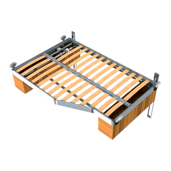
Maintenance Introduction The Smart Bed™ Universal Kit distributed by Lippert Components, utilizes a unique nylon strap-based system, adaptable to a broad range of RV and heavy truck applications including cabs, living rooms, slide- out rooms and master bedrooms. The straps retract into the bed base, concealing the lifting system in the retracted position, permitting OEMs more floor plan design freedom. -
Page 3: Safety
Safety Read and understand all instructions before installing or operating this product. Adhere to all safety labels. This manual provides general instructions. Many variables can change the circumstances of the instructions, i.e., the degree of difficulty, operation and ability of the individual performing the instructions. This manual cannot begin to plot out instructions for every possibility, but provides the general instructions, as necessary, for effectively interfacing with the device, product or system. -
Page 4: Resources Required
Resources Required • Cordless or Electric Drill or Screw Gun • Socket Wrench (8 mm) • Pneumatic Rivet Gun With Extended Tip • Rubber Mallet • Pneumatic Staple Gun • Super Lube® Grease • Appropriate Drive Bits • High Strength Red Loctite •... - Page 5 Starting at one end rail, insert a corner cap key (Fig. 2A) into each end of the rail (Fig. 2B). Use a rubber mallet to make sure the corner cap keys are connected tight within the end rail. NOTE: The end rails should stop at the notched top (Fig. 2C) and bottom edge of the corner cap (Fig. 2D). Repeat step 4 and step 5 for the rest of the corner caps.
-
Page 6: Center Rail Support
11. If applicable, bend the bendable flat bracket (Fig. 7A) to the desired angle for each joint assembly. 12. Place the bendable flat bracket centered over the assembled joint and just under the slat and insert channel (Fig. 7B) on the side rail. 13. -
Page 7: Slat Brackets And Wood Slats
Slat Brackets and Wood Slats NOTE: Wood slats will be cut to length for different bed sizes. Refer to model print for quantity. Locate a left and a right slat bracket (Fig. 10A). With the insert tabs facing down, insert three wood slats (Fig. - Page 8 Create an approximate 3" gap from the end rail's insert channel to the first wood slat on both sides of the center rail support (Fig. 13A). Make sure the wood slats installed on either side of the center rail support are even with each other (Fig. 13). Fig.
- Page 9 10. Flip the assembled bed frame bottom facing up throughout the rest of the Smart Bed assembly. The assembled center rail support (Fig. 15A), wide flat side, will be facing up. Fig. 15 Page 9 Rev: 12.28.22 CCD-0004051...
-
Page 10: Belt And Stabilizer Guide Brackets
Belt and Stabilizer Guide Brackets Belt Brackets NOTE: The proper belt bracket locations will depend on the type of Smart Bed Lift configuration and where the motor is installed. Measure from the corner edge out on the end rail with the supplied measurements for each Smart Bed Lift model. -
Page 11: Mounting Channel Brackets
Stabilizer Guide Track Bracket Install the stabilizer guide track brackets (Fig. 18A) as close as possible to the side of the bed to avoid a tip-over when under load. NOTE: The stabilizer guide track bracket (Fig. 18A) locations may vary per bed. Place the stabilizer guide track bracket (Fig. -
Page 12: Drive Shafts And Belts
Drive Shafts and Belts NOTE: If the drive shaft needs to be cut down to fit the Smart Bed Lift dimensions, make sure to clean the center hole of the drive shaft with a drill bit. Locate two long belts (Fig. 22E), two short belts (Fig. 22D) long drive shaft (Fig. 22B) short drive shaft (Fig. - Page 13 Install a pin strap fastener (Fig. 24B) into the loop end of the long belt (Fig. 24A). With the pin strap legs facing down towards the bottom of the drive shaft, and the seam of the belt facing out away from the drive shaft, thread the pin strap fastener with the long belt installed into the short drive shaft channel on the left side of the drive shaft.
-
Page 14: Drive Shaft Header Assembly
Drive Shaft Header Assembly The drive shaft header assembly will be installed on one side of the short drive shaft (Fig. 27) and one side of the long drive shaft (Fig. 28). Make sure that the header is installed on the correct side of the drive shafts prior to installing on the bed frame. -
Page 15: Drive Shaft And Motor Installation
Use a hex key to tighten the M6 screw with assembly onto the drive shaft end plate (Fig. 29H). NOTE: Make sure the o-ring (Fig. 29D) is not compressed beyond the zinc fender washer (Fig. 29C). Repeat steps 1-5 for the long drive shaft end. Drive Shaft and Motor Installation Refer to (Fig. - Page 16 Fig. 31 Fig. 31 Viewing from underneath, up, towards the end rail frame. Insert the ACS module (Fig. 32B) into the ACS module holder (Fig. 32A). Make sure the ACS module key (Fig. 32C) is aligned with the ACS module keyway (Fig. 32D) in the ACS module holder. Push and turn the ACS module until ACS module seats into place (Fig.
- Page 17 If not already installed, install two 2.9 x 9.5 mm screws (Fig. 30N) one on each side of the ACS module holder (Fig. 30A) holding the two half's of the ACS module holder together. Slide the ACS module holder (Fig. 33B) underneath the angle support bracket (Fig. 33A). Align the angle support bracket holes with the ACS Module holder.
-
Page 18: Motor Mount Support And Bracket
Drive Shaft Centering Bracket Measure from the outside end rail to the end of the drive shaft header center brackets (Fig. 34A) with the supplied measurements for each Smart Bed Lift model. Move the long and short drive shaft header center brackets into place so that both sides are even. - Page 19 Fasten the motor mounting bracket (Fig. 36A) to the motor mount support adjustable slot (Fig. 35E) with two 4.2 x 13mm screws (Fig. 36C). Also refer to Figure 31Q for the screw holes in the mounting bracket. Fig. 36 Place the opposite end of the motor mounting bracket (Fig. 37A) onto the motor mounting channel bracket (Fig.
-
Page 20: Belt Mounting Brackets
Belt Mounting Brackets Remove the tape holding the belts in the rolled-up position on the drive shaft. Feed the short belts into the closest end rail belt brackets (Fig. 38A) and feed the long belts into the opposite end rail belt brackets (Fig. 39A). Fig. - Page 21 With the bed frame supported and at the fully retracted position, measure from the desired belt mounting bracket position to the bottom of the bed on both sides. The measurement from the bottom of the belt mounting bracket (Fig. 422A) to the bottom of the bed frame (Fig. 42C) should be at a minimum of 100 mm (3 15/32 in).
- Page 22 11. Wrap the belt (Fig. 43C) over the top of the first belt plate (Fig. 43B). The belt extending up from the bed frame should be in between the belt mounting bracket and the belt plate. 12. Place the belt plate and the belt onto the posts (Fig. 43A) of the belt mounting bracket. 13.
-
Page 23: Stabilizer Channel Guides
Stabilizer Channel Guides Stabilizer Channel Guides have different properties depending on the shape, but generally they should be mounted furthest away from each other, and on the side of the bed facing the front of the vehicle. This is because it’s the safest position, since the mass of the bed during braking or crash is at least partially supported by the internal structure and furniture of the vehicle. -
Page 24: Operation Switch
Operation Switch NOTE: If installing on a unit with aluminum backing in the wall, use a minimum size of #10 x 1.00" self-drilling screws. If installing on a unit with wood backing in the wall, use a minimum size of #10 x 1.00" wood screws. The operation switch can be installed in the wall of the unit next to the bed frame or if installing padded rails to the bed frame, in the padded rails. -
Page 25: Wiring Diagram
Wiring Diagram Fig. 52 Power Controller ACS Module Main Wire Harness Switch Harness Back of Switch Battery Motor Page 25 Rev: 12.28.22 CCD-0004051... - Page 26 For Reference Only Page 26 Rev: 12.28.22 CCD-0004051...
-
Page 27: Setting The Acs Stop Procedure
Setting the ACS Stop Procedure Setting the UP Position Make sure the safety belts are unfastened. Turn the key switch to the ON position (Fig. 59B) located on the key switch. Press and hold the UP arrow-shaped button (Fig. 59C) on the key switch. The bed will keep moving until you reach the pre-set stop position. -
Page 28: Flex Track For Wires
Flex Track For Wires Prior to installing the Flex Track, make sure the Smart Bed Lift is in its fully extended position. Position the Flex Track under the bed frame, where the wiring needs to be protected. NOTE: The Flex Track is designed so that it only articulates or bends in one direction. Do not attempt to bend the Flex Track in a direction it does not freely move. -
Page 29: Safety Belt Harness
Safety Belt Harness The safety belt harness (Fig. 58A and 58B) will need to be fastened one side to the bed frame and the other side to the ceiling of the unit, on both sides of the bed frame. In some cases it’s better to have the female plug (Fig. -
Page 30: Operation
Operation Always make sure that the Smart Bed Lift path is clear of people, pets and objects before and during operation. Always keep away from the slide rails when the bed is being operated. Do not allow people or pets on bed while it is in motion. Prior to Operating the Smart Bed Lift System The Smart Bed Lift system must never be used while the vehicle is in motion. -
Page 31: Manual Override
Manual Override Always disconnect from power source before performing any operation on the Smart Bed Lift System To raise or lower the Smart Bed Lift in case of emergency, it is possible to operate the system manually. Insert the provided crank device (Fig. 60A) into the motor (Fig. 60B). Turn clockwise to raise or counterclockwise to lower the bed. - Page 32 Lippert representative has been provided. Any unauthorized use shall void any applicable warranty. The information contained in this manual is subject to change without notice and at the sole discretion of Lippert. Revised editions are available for free download from lippert.com.
Need help?
Do you have a question about the SMART BED UNIVERSAL KIT and is the answer not in the manual?
Questions and answers