
Subscribe to Our Youtube Channel
Related Manuals for Lippert Level-Up


Summary of Contents for Lippert Level-Up
- Page 1 Lippert Level-Up Motorhome Leveling ® Winnebago Industries 9-2015 to Present OWNER'S MANUAL...
-
Page 2: Table Of Contents
TABLE OF CONTENTS System Prior to Operation System Description Component Description Maintenance Fluid Recommendation Preventative Maintenance Fitting Orientation Controls Features System Wiring Requirements Air and Auxiliary Features (When Applicable) Level Zero Point Calibration Error Mode Excess Slope User Alarm Mode Miscellaneous Low Voltage Signal Operation... -
Page 3: System
People and pets should be clear of coach while operating leveling system. Be sure to keep hands and other body parts clear of fluid leaks. Oil leaks in the Lippert Level-Up Motorhome Leveling System for Winnebago Industries may be under high pressure and can cause serious skin penetrating injuries. -
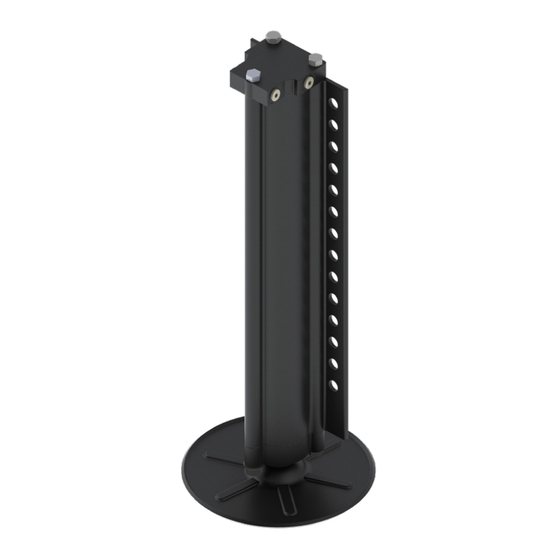
Page 4: System Description
DC electric motor drives a hydraulic pump that moves fluid through a system of hoses, fittings and jacks to level and stabilize the coach. Mechanical portions of the Lippert Level-Up Motorhome Leveling System for Winnebago Industries are replaceable. Contact Lippert Components, Inc. to obtain replacement parts. See page 18 for the Bill Of Materials list. Component Description Jacks A. - Page 5 The coach should be supported at both front and rear axles with jack stands before working underneath. Failure to do so may result in death or personal injury. If jacks are down for extended periods, it is recommended to spray exposed leveling jack rods with a silicone lubricant every three months for protection.
-
Page 6: Fitting Orientation
Fitting Orientation NOTE: Fittings - High pressure O-Ring Face - Size 4 ¼ NOTE: Hose - in. I.D. 3000 psi - W.P. Rated Fig. 4 Callout Part # Description 177094 174184 Valve/Coil - Rear Jacks 142927 Pressure Switch Filler Vent Extend Fittings 156846 141109... -
Page 7: Controls
Controls Fig. 5 Callout Description Up Arrow - Scrolls up through the menu on LCD. Down Arrow - Scrolls down through the menu on LCD. Enter - Activates modes and procedures indicated on LCD. Retract - Places leveling system into retract mode. - Manual mode ONLY LCD Display - Displays procedures and results. -
Page 8: Features
Features A. Automatic extension of jacks from full retract position (with automatic ground detection). B. Automatic leveling of jacks. C. Manual leveling of jacks D. Automatic retraction of jacks (with automatic full retract detection). Air bag suspension features (configurable on/off). Jacks Up Verification (jacks not retracted and park brake disengaged). -
Page 9: Level Zero Point Calibration
Level Zero Point Calibration Before auto-leveling features are available, the Level Zero Point must be set. This is the point to which the system will return when an auto leveling cycle is initiated. To set the Zero Point (controller module must be fully secured in production-intent location), first run a manual leveling sequence to get the vehicle to the desired level point. -
Page 10: Error Mode
Error Mode A. If an error occurs before or during operation, the error will be displayed in the LCD and an alarm will sound. To reset common ERROR displays, press ENTER (Fig. 5C). NOTE: To reset "Return for Service" errors, press "ENTER" (Fig. 5C) and "RETRACT" (Fig. 5D) simultaneously. B. -
Page 11: User Alarm Mode
NOTE: Refer to Component Description on page 4 and page 7 (Fig. 5) for questions regarding location and functions of the Lippert Level-Up Motorhome Leveling System for Winnebago Industries system. NOTE: Coach must be running and parking brake must be engaged for Lippert Level-Up Motorhome Leveling System for Winnebago Industries to operate. -
Page 12: Automatic Leveling Descriptive Logic
Automatic Leveling Descriptive Logic Grounding: Steps 1 - 7 describe the process of how the AUTO LEVEL LOGIC extends the jacks to the ground: Depending on which end of the coach is lowest to the ground the level sensor in the controller will activate the jacks, one at a time on the lowest end first, either front or rear. -
Page 13: Jack Retract Procedures
Repeat steps 2 through 7 as needed. Turn power off to leveling system by Pressing ON/OFF button (Fig. 5K). 10. Visually inspect all jacks to ensure all footpads are touching the ground. Should one of the rear jack footpads not be touching the ground, press the corresponding LEFT or RIGHT arrow buttons to lower the non-compliant jack to the ground. -
Page 14: Remote Leveling Operation
Remote Leveling Operation TO BEGIN - INSIDE COACH - Press ON/OFF button. ON/OFF LED on TOUCH PAD will Fig. 8 illuminate. LED at REMOTE SWITCH will also illuminate. Ready to operate. OUTSIDE COACH - Press ROCKER SWITCH (Fig. 6) for operation. AUTOMATIC MODE - Press ROCKER SWITCH and release toward LEVEL (Fig. -
Page 15: Manual Override - Power System
Manual Override - Power System The Lippert Level-Up Motorhome Leveling System for Winnebago Industries can be run with auxiliary power devices like cordless or power drills. In the event of electrical or system failure, this manual method of extending and retracting the jacks can be used. A standard handheld drill is all that is required. See the instructions below. -
Page 16: Wiring Diagram
Wiring Diagram Touch Pad Controller Main Touch Pad Harness Rear Harness Sensor (Winnebago Only) Interconnect Rear Sensor Harness Harness Power Unit To OEM Harness Supplied Harness Power Unit Directional Valve Pressure Switch Manifold Coil Page 16 Rev: 06.29.2022 CCD-0001536... -
Page 17: Plumbing Diagram
Plumbing Diagram Right Front Jack Left Front Jack NOTE: Orange - Retract Black - Extend Power Unit Retract Right Rear Jack Left Rear Jack Extend Page 17 Rev: 06.29.2022 CCD-0001536... -
Page 18: Bill Of Materials
Bill of Materials Description Part # Details Quantity Hydraulic Power Unit, Leveling Only 293414 Power Unit Hydraulic Power Unit, Leveling Only 293559 Motor 12VDC Motor for Power Unit 179327 Solenoid 161394 Motor Solenoid Valve Blocking Valve 177094 Electromagnetic Coil for Blocking Coil 174184 Valve... -
Page 19: Troubleshooting Guide
“jacks down” Low fluid Level. jacks retracted. If "JACKS DOWN" light displayed, jacks are retracted. remains on, call Lippert Service. Little or no fluid in reservoir. Add fluid as recommended; See page 4. Valve is inoperative. Clean, repair, or replace. - Page 20 The contents of this manual are proprietary and copyright protected by Lippert Components, Inc. (LCI). LCI prohibits the copying or dissemination of portions of this manual unless prior written consent from an authorized LCI representative has been provided. Any unauthorized use shall void any applicable warranty. ...
Need help?
Do you have a question about the Level-Up and is the answer not in the manual?
Questions and answers