Lippert SlimRack Plus Maintenance, Troubleshooting And Service Manual
Slide-out system
Hide thumbs
Also See for SlimRack Plus:
- Owner's manual (16 pages) ,
- Oem installation manual (34 pages)
Table of Contents
Advertisement
Quick Links
Advertisement
Table of Contents

Subscribe to Our Youtube Channel
Related Manuals for Lippert SlimRack Plus


Summary of Contents for Lippert SlimRack Plus
- Page 1 SlimRack Plus ® Slide-out System TROUBLESHOOTING AND SERVICE MANUAL...
-
Page 2: Table Of Contents
Wiring Diagram - Motorized Introduction The Lippert SlimRack® Plus Slide-Out system maximizes interior RV space by providing added comfort and offering a practical solution for additional space needs. This document provides information to assist in determining causes of concerns with the operation of the SlimRack® Plus In-Wall Slide-Out system and detailed instructions on repairing and servicing various components of the system. -
Page 3: Safety
Failure to correctly follow the provided instructions may result in death, serious personal injury, severe product and/or property damage, including voiding of the Lippert limited warranty. The "WARNING" symbol above is a sign that a procedure has a safety risk involved and may cause death or serious personal injury if not performed safely and within the parameters set forth in this manual. -
Page 4: System Information
Performing an Initial Synchronization once at the factory. • Floor rollers (not supplied by Lippert) that support the slide-out's weight while extending and retracting the slide-out. Only floor rollers approved by Lippert can be used with the system. Contact Lippert for recommended rollers. -
Page 5: Troubleshooting
Troubleshooting Checking Circuit Breakers The SlimRack Plus Slide-out requires a minimum of a 30-amp circuit breaker. Check the 12-volt circuit breaker box for blown circuit breakers, and replace any if necessary. Consult the RV manufacturer's documentation for the location of the 12-volt circuit breaker box, and the location of the slide-out controller’s circuit breaker. -
Page 6: Measurements
Measurements Measure from the outside edge of the column to the side of the slide out wall (Fig. 3). The standard measurement tolerance should be 3 7/8" plus or minus 1/8". Take this measurement on both sides when the room is fully extended and again when the room is 3" from fully retracted. Measure the gear racks for parallelism. -
Page 7: Mode Button
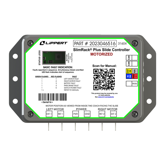
Mode Button The SlimRack Plus Slide-Out controller (Fig. 3) detects several faults. LEDs on the controller are used to indicate when the controller is driving a slide-out and faults. The QR code on the controller can be scanned with a mobile phone camera and leads to more troubleshooting documentation. -
Page 8: Switching Between Operating Modes
Switching Between Operating Modes It is possible to switch between operating modes using the mode button. The controller will return to normal operating mode on its own after 2 minutes, even if being driven. NOTE: When in electronic override mode, electronic protections will be disabled. Operating Modes Presses Function... -
Page 9: Led Indications
LED Indications • When driving motors, the green LED and red LED will blink synchronously. • When indicating faults, the LEDs blink sequentially, report all faults and repeat. The green LED will blink once or twice to indicate the reporting mode, followed by one to several blinks of the red LED to indicate each fault. -
Page 10: Factory Reset And Initial Synchronization
Basic Fault Reporting Mode Table Green LED (1 = basic fault DTC: Diagnostic reporting mode, Description Troubleshooting Steps Trouble Code 2 = DTC reporting mode) Check connections on the motor, There is a problem the controller and check the wire 1 (Basic fault) Motor 1 fault with the motor 1... - Page 11 DTC Reporting Mode Table Green LED (1 = basic fault reporting mode, DTC: Diagnostic Trouble Code Description Troubleshooting Steps 2 = DTC reporting mode) One of the motor 1 DTC_MOTOR_OUTPUT_1_ Check motor harness 2 (DTC) outputs is shorted SHORT_TO_GND for damage. to ground.
- Page 12 DTC Reporting Mode Table Green LED (1 = basic fault reporting mode, DTC: Diagnostic Trouble Code Description Troubleshooting Steps 2 = DTC reporting mode) Check controller Motor 1 output DTC_MOTOR_OUTPUT_1_ and motor for loose 2 (DTC) became open after OPEN_B connections.
-
Page 13: Maintenance
No action required. Maintenance The Lippert slide-out system has been designed to require very little maintenance. To ensure the long life of the slide-out system, follow these simple procedures: When slide-out room is extended, visually inspect the slide gear rack assemblies. Check for excess buildup of dirt or other foreign material. -
Page 14: Wiring Diagram - Towable
Wiring Diagram - Towable Fig. 5 Wall Switch Slide-Out Controller OEM- Supplied Wire Connector 30 Amp Circuit To Chassis Breaker Page 14 Rev: 06.27.24 CCD-0008630... -
Page 15: Wiring Diagram - Motorized
Wiring Diagram - Motorized Fig. 6 Wall Switch Slide-Out Controller To Park Brake Signal OEM- Supplied Wire Connector 30 Amp Circuit To Chassis Breaker Page 15 Rev: 06.27.24 CCD-0008630... - Page 16 Lippert representative has been provided. Any unauthorized use shall void any applicable warranty. The information contained in this manual is subject to change without notice and at the sole discretion of Lippert. Revised editions are available for free download from lippert.com.
Need help?
Do you have a question about the SlimRack Plus and is the answer not in the manual?
Questions and answers
controller is flashing 4 red lights. front slide outs and awnings not working