Modine PTP, BTP, PTC, BTC, PTS, BTS, PDP, BDP Manual
- Installation and service manual (20 pages) ,
- Manual (12 pages) ,
- Installation instructions (2 pages)
Advertisement
FEATURES AND SPECIFICATIONS
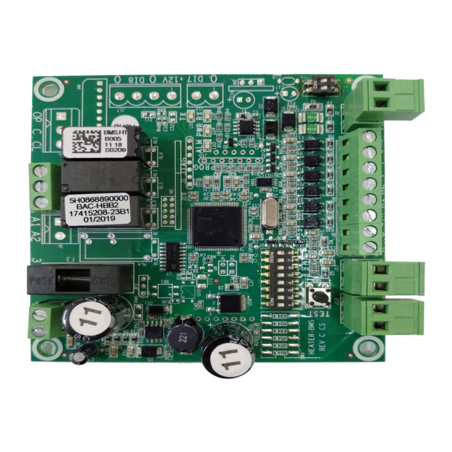
MODINE BMS BOARD FOR GAS-FIRED UNIT HEATERS
The Modine Building Management System (BMS) Board installed in this unit provides an RS485 interface between the unit heater and existing building networks that employ a BACnet or Modbus protocol. The board works in conjunction with the unit's ignition control module to manage and report the function of the heater. A BMS network connection is not required to operate the heater, but allows for expanded control and monitoring ability.
FEATURES
The BMS Board is capable of the following features:
Energy Saver Function
The BMS Board is wired to a 10K NTC Type III inlet air sensor that provides feedback of the air temperature at the unit's installed height. When the unit is operating in this mode, the unit will turn on the fan only when a call for heat is received, using the warmer air at the unit to destratisfy the building space before using the valve to further heat the space.
Input Monitoring
The BMS board receives statuses from the components on the unit heater to make sure that operation of the unit is normal, and communicates status over the network. If the board detects statuses that indicate an issue with normal operation, alarm codes will be sent over the network. In addition, the board's "ALM" LED will illuminate on the BMS board.
Temperature Control Flexibility
The BMS board is designed to take room air feedback from a traditional low voltage mechanical/programmable thermostat or a 10K NTC Type III sensor (Modine FP48335).
Enhanced BMS Control
By employing BMS control over the provided RS485 connection, the unit is capable of receiving commands such as Supervisor On-Off functions, defining summer/winter functionality, and changing space setpoints. The board will also send statuses for components such as the fan and gas valve, and communicate alarms over the network.
BOARD SPECIFICATIONS
Terminals
All terminals shall be slotted screw appropriate for 24-12ga wire.
Power
Class II Transformer secondary voltage supplied to the control shall be 18.0 to 30.0 VAC, 50/60 Hz. Power requirements of the control is 12.0 VA max at 24 VAC plus external loads.
ENVIRONMENTAL
Temperature
Operating: -22° to 176°F (-30° to +80°C)
Storage: -40° to 185°F (-40° to +85°C)
Humidity
Operating: 10% to 95%, non-condensing, -22° to 113°F (-30° to +45°C )
Storage: 10% to 95%, non-condensing
Vibration
No damage or misoperation from 5g sinusoidal acceleration, 10 to 150 Hz.
Mechanical Impact
No damage or misoperation from 3 foot-pound impact to mounting enclosure when control is properly mounted.
Changing space setpoints. The board will also send statuses for components such as the fan and gas valve, and communicate alarms over the network.
Dust/Environment Protection
The BMS Board is conformally coated.
RELIABILITY
Operating Life
12 year minimum design life based on the following duty cycles:
Heating 2500 hours, 15000 cycles per year
Cooling (Fan Only) 2500 hours, 7500 cycles per year
INPUTS/OUTPUTS:
ANALOG INPUTS (2 - 10KOhm NTC Type III Channel)
- Return Air (This input shall be ignored when the dip switch is in T-stat position)
- Intake Air
ANALOG OUTPUTS (0)
None.
DIGITAL INPUTS (6 – 24VAC input)
- Gin – Fan Call. This input shall be ignored when dip switch SW4.7 is in on position.
- W1 – Heating Call (Stage 1) (This input shall be ignored when dip switch SW4.7 is in on position)
- W2 – Heating Call (Stage 2) (This input shall be ignored when dip switch SW4.7 is in on position)
- Valve Status
- Pressure Switch Status
- High Limit / Flame Rollout Status
DIGITAL OUTPUT (3 – Normally Open, 24VAC switch)
- G, Blower – 24VAC
- H1 Gas Valve, Single-Stage or Low Stage – 24VAC
- H2, Gas Valve, High Stage – 24VAC
CONFIGURING BOARD OPERATION
During unit installation, verify the BMS board is set up to operate correctly with the room air temperature feedback method. Use SW4.7 dipswitch to select desired operation.

BMS BOARD FUNCTION
Space Temperature Feedback Method
ON – 10K Ohm NTC Type III Sensor
OFF – Mechanical/Programmable Thermostat (default)
HEATING THERMOSTAT CONTROL
If thermostat signals are provided as digital inputs (dip switch SW4.7 must be set "off" for T-stat operation), the unit will call for heat when the thermostat passes 24VAC to W1. The BMS Board comes factory set for this operation. When a W1 signal is received, the Gas Valve Stage output H1 will energize. When a W2 signal is received, the Gas Valve Stage 2 output H2 will be energized. When the W2 call is removed, the Gas Valve Stage 2 output H2 will be de-energized. When the W1 call is removed, the Gas Valve Stage 1 H1 output will be de-energized.
SENSOR CONTROL
If a return air signal is provided (wired into analog input T1, dip switch SW4.7 must be set "on" for sensor operation), there will be a call for heat whenever the sensor reads 1°F lower (setpoint_band default value, 1°C) than the heat_setpt_BMS value (default 70°F, 21°C). Once this temperature has been reached, Gas Valve Stage 1 output H1 will be energized. If the temperature drops an additional 2°F (1.1°C), the Gas Valve Stage 2 output H2 will be energized. H2 will de-energize when the temperature raises to the temperature that originally turned on stage 1 heating. When the temperature returns to the setpoint (heat_setpt_BMS) value, output H1 will be de-energized.
ENERGY SAVER FUNCTION
If the Intake sensor T2 is reading 85°F (saver_setpt_BMS default value, 29°C) or above when the sensor or W1 signal calls for heat, the board shall only energize the Blower output G, until the sensor or W1 call is removed, or until the intake sensor drops 3°F lower (saver_band default value, 1.5°C) than the saver_setpt_BMS value.
BMS CONTROL CHANGING THE UNIT CONTROL OVER NETWORK
If the BMS is sending a Superv_OnOff parameter of 'off' to the unit, the equipment will not energize an output regardless of sensor/stat inputs.
If the unit is operating with sensor control, the value of the space setpoint, band, and energy saver setpoint can be adjusted over BMS network. If unit is not on BMS network and running in sensor control, the unit will operate at default values per Table 6.1 & 7.1. If the unit is running in thermostat control, the setpoints and bands will be governed by the thermostat.
The unit may be set over BMS to run in summer mode by changing the summer_winter digital variable address value to 1. See the 'FAN ONLY' section for more details about unit control in this mode. The unit ships with the default value for this address at '0', which puts the unit in winter mode for normal heating function.
The unit temperature values can be changed to report temperatures in °C instead of °F by changing the C_F_Scale object value to 1 (°C) instead of 0 (°F, factory default).
All modes and setpoint/band values can be restored to their factory setting by setting the RestoreDefault object value to 1 (the value will self-reset to 0).
MONITORING UNIT STATUS
The unit will report the status of various component and space conditions over BMS network as it operates. See the description of the object list in Tables 6.1 & 7.1 for more information about the points.
BMS ALARMS
If the board reads an analog input temperature on any channel below -150°F (-101°C) or above 200CF (93°C), the unit will display an al_BrokenPrbTemp alarm, and the board should not energize any output as long as the condition persists. On analog input 1, this only applies if unit is operating on sensor control (dip switch set to sensor control). If a unit is operating on stat control, the al_BrokenPrbTemp alarm will only be used regarding analog input 2 (intake air).
al_highlimit_FRO_alarm will be indicated if there is a call for heat and no signal through the high limit(s) or flame rollout switch(es) to the Lim input terminal. Unit would trigger immediate alarm. Alarm status will clear when signal closes.
al_pressure_switch will be indicated when there is a call for heat, but the pressure switch is not pulled in and no signal to P input terminal. There is a 90 second delay before pressure switch status is observed, and requires a continuous 60 second loss of pressure switch signal to generate the alarm. Chattering of a pressure switch will not trigger alarm. When there is no call for heat the pressure switch should be open. If it isn't, the alarm will be indicated if the status is closed for over 90 continuous seconds. The al_pressure_switch alarm will be ignored if other alarms are already present.
al_valve_ignition_alarm will be indicated when there is a continuous call for heat for at least 300 seconds, there are no other unit alarms, and the gas valve signal is not present on V input terminal. This alarm will be cleared when valve status is closed for 15 continuous seconds.
All alarms will reset on power cycle.
FAN-ONLY
The unit can receive a fan-only call in two ways. A unit can be set by BMS to have the summer_winter variable set to 1 (summer mode) for the unit to energize a fan-only call. If a return air signal T1 is provided (dip switch SW4.7 must be set "on" for sensor operation), the unit will call for fan-only when the sensor reads 1° (value of setpoint_band) higher than the fan_setpt_BMS value (default 75°F, 24°C). Once this value has been reached, the Blower output G will be energized. When the return air temperature returns to the setpoint, the Blower output G should be de-energized.
Alternately, if thermostat signals are provided as digital inputs, the unit will call for fan operation on a G signal. When a G signal is received, the Blower output will be energized. When the G call is removed, the Blower output will be de-energized.
Wiring Connections
Field connections must follow the wiring diagram supplied with the unit. Terminal boards may be factory-supplied on your unit heater for external stat connections (See Figure 4.1 It may be required to route some wiring directly to the BMS Board, which may be internal to the control cabinet. In these cases, you may puncture the provided rubber grommet to route cabling into the control area (See Figure 4.2).
WIRING CONNECTIONS

SETTING NETWORK ADDRESS Figure 4.3
Each unit utilizing a BMS Board should have a unique address assigned to allow the network to recognize the independent feedback from each heater. The address can be set from a value between 0-63 using dipswitches SW4.1 to SW4.6. Use the table below to set the dipswitches as needed.

CONFIGURING BMS PROTOCOL
During unit installation, verify the BMS board is set up to communicate to the desired BMS protocol Use SW4.8 dipswitch to select desired operation.
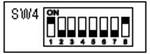
SW4.8: BMS Communication Protocol
ON – BACnet (default)
OFF – Modbus
BACnet MSTP
TimeOut 100 ms Baud rate: 9600, 19200, 38400
End of line resistor SW1.1 should be set to ON
The Device ID communicated over the network will be equal to 315000 plus the MAC address value assigned via the dipswitches or over the network. For example, a unit with dipswitch settings set to an address of "1" will have a Device ID of 315001. If the MAC address is written over the network, the dipswitch positions will be ignored unless the 'RestoreDefault' parameter is set to 1.

For the last unit in the network only, do not set switch ON for the intermediate units
MODBUS
RTU Mode, Address Slave 1-247, Baud rate: 9600, n, 8, 1
Supported Commands: 0x03 = Read Holding Registers (for all). 0x06 = Preset Single Register (For R/W registers only).
Note 1. The MODBUS Register No. X is addressed in the MODBUS Register Address (PDU) X-1.
All Registers are signed Integer 16 bit
| Objectld | Object Name/Description | Type | M/O | Category |
| 0x00 | VendorName | ASCII String | Mandatory | Basic |
| 0x01 | ProductCode | ASCII String | Mandatory | Basic |
| 0x03 | MajorMinorRevision | ASCII String | Mandatory | Basic |
VendorName = "Meitav-Tec Ltd".
ProductCode = "17415208"
MajorMinorRevision = "0.1.1888"
Function 0x2B (Encapsulated Interface Transport)
MEI Type 0x0E (Read Device Identification)
Read Dev ID code 0x02 (request to get the Regular Device Identification)
| Objectld | Object Name/Description | Type | M/O | Category |
| 0x03 | VendorURL | ASCII String | Optional | Regular |
| 0x04 | ProductName | ASCII String | Optional | Regular |
| 0x05 | ModeName | ASCII String | Optional | Regular |
| 0x06 | UserApplicationName | ASCII String | Optional | Regular |
VendorUrl = "meitavtec.com"
ProductName = "BAC_HBB2" ModelName = "17415201"
UserApplicationName = "BAC_HBB2"
End of line resistor SW1.1 should be set to ON

For the last unit in the network only, do not set switch ON for the intermediate units.
BMS OBJECT LIST AND DEFAULT VALUES
BACNET
Table 6.1: BACnet MSTP Object List

* If a setpoint outside of the range defined above is sent via BMS to the controller no change will happen and the unit will continue to operate to the last known setpoint.
MODBUS
Table 7.1: Modbus FC Object List

* If a setpoint outside of the range defined above is sent via BMS to the controller no change will happen and the unit will continue to operate to the last known setpoint.
TROUBLESHOOTING
| TROUBLE | POSSIBLE CAUSE | DETECTION | POSSIBLE REMEDY |
Unit is not providing heat | Thermostat malfunction (when used) | On call for heat, 24VAC should exist between W1 and C on the BMS board. | Verify wire connections per wiring diagram. Make sure board dipswitch SW4.7 is set to OFF. Check/replace thermostat. |
| No 24V power to BMS board or thermostat | "PWR" LED will be illuminated on BMS board when 24VAC is present between R and C terminals. | Verify wiring connections per wiring diagram. Check/replace transformer. | |
| Blown fuse on BMS board | Visual and/or continuity across fuse. | Replace fuse. | |
| Return air sensor malfunction (when used) | "ALM" LED will be illuminated on board when sensor reading falls out of range (-50-200°F). Reference Table 9.1. | Verify wiring connections per wiring diagram. Make sure board dipswitch SW4.7 is set to ON. Check/replace sensor. | |
| Unit is turned off by supervisor, set to summer mode, or has not reached heating setpoint (BMS). | Scan points list over network (see BMS Object List). | Change status over network. | |
| Unit is operating in energy saver mode. | In energy saver mode, the fan will run without burner operation while there is a call for heat. No alarms will be present. | Verify intake probe is reading accurately. Unit should call for gas valve to open when intake air falls 3°F (default) below energy saver setpoint (80°F default). Test" button may be pressed twice rapidly to force all temperature inputs to 60°F for a duration of 5 minutes or until power reset. The unit will energize the valve on a call for heat over this time. | |
| Unit is in alarm | "ALM" LED will be illuminated on board, one of the alarm statuses listed below will be communicated over network. | Verify wire connections per wiring diagram. Check for ignition controller flash codes for further diagnostic. | |
| al_BrokenPrbTemp | Intake Air or Return Air Sensor, or wiring to those sensors, may be faulty. Replace or repair. Refer to table 9.1 for reference sensor resistance. | ||
| al_highlimit_FRO_alarm During a call for heat, 24VAC should exist between Lim and C on the BMS board. | Unit may have tripped auto or manual reset limit switch during call for heat, or condensate overflow switch (PTC/BTC units only) has tripped. Verify wiring connections per wiring diagram. Consult heater I&S and ignition control literature. | ||
| al_pressure_switch During a call for heat, 24VAC should exist between P and C on the BMS board. | Pressure switch has not pulled in during call for heat, or power exhauster manual reset limit has tripped (PTC/BTC only). Verify wiring connections per wiring diagram. Consult heater I&S and ignition control literature. | ||
| al_valve_ignition_alarm During a call for heat, 24VAC should exist between V and C on the BMS board. | Gas valve has not consistently energized during call for heat. Verify wiring connections per wiring diagram. Consult heater I&S and ignition control literature. | ||
| BMS Board relay failure | Remove inputs from board (W1, W2, Gin, V, P, Lim) and hold "Test" button down for over 5 seconds. If relays work properly, the "ALM" LED will blink 1 second on, 3 seconds off. If there is a relay failure, the LED will blink 1 second on, 1 second off. | Check board fuse. Replace BMS board. Call for heat may be rewired from W1 of BMS board directly to ignition controller (replacing H1 wire) to continue unit operation (network statuses will not be accurate if done). | |
Unit is not communicating over BMS | Board is set to incorrect protocol | Scan points list over network. "Tx/Rx" LEDs will rapidly flash when communicating, and will be solid on if reversed. | Make sure board dipswitch SW4.8 is set as needed. |
| Unit is addressed incorrectly or duplicate. | Check address settings on dipswitches SW4.1 to SW4.6. and over BMS. If the address is assigned over BMS and the 'RestoreDefault' point has been utilized, the unit address will default back to the address assigned via the dipswitch setting. | ||
| Incorrect wiring | Verify wire connections per wiring diagram. Make sure correct wires are used on A/B terminals of plug. |
Table 9.1 – 10K NTC Type III Sensor Reference Temperatures.
| Temperature | Resistance | |
| °C | °F | Ohms (Ω) |
| 5 | 41 | 23460 |
| 6 | 42.8 | 22430 |
| 7 | 44.6 | 21440 |
| 8 | 46.4 | 20510 |
| 9 | 48.2 | 19620 |
| 10 | 50 | 18780 |
| 11 | 51.8 | 17980 |
| 12 | 53.6 | 17210 |
| 13 | 55.4 | 16480 |
| 14 | 57.2 | 15790 |
| 15 | 59 | 15130 |
| 16 | 60.8 | 14500 |
| 17 | 62.6 | 13900 |
| 18 | 64.4 | 13330 |
| 19 | 66.2 | 12780 |
| 20 | 68 | 12260 |
| 21 | 69.8 | 11770 |
| 22 | 71.6 | 11290 |
| 23 | 73.4 | 10840 |
| 24 | 75.2 | 10410 |
| 25 | 77 | 10000 |
| 26 | 78.8 | 9602 |
| 27 | 80.6 | 9226 |
| 28 | 82.4 | 8866 |
| 29 | 84.2 | 8522 |
| 30 | 86 | 8194 |
Safety

- Disconnect power supply before making wiring connections to prevent electrical shock and equipment damage.
- Installation of wiring must conform with local building codes, or in the absence of local codes, the National Electric Code, ANSI/NFPA 70 – latest edition. Unit must be electrically grounded in conformance to this code. In Canada, wiring must comply with CSA C22.1, Electrical Code.
- The unit must be wired strictly in accordance with the wiring diagram furnished with the unit. Any wiring different from the wiring diagram could result in a hazard to persons and property.

- The use of this manual is specifically intended for a qualified installation and service agency. A qualified installation and service agency must perform all installation and service of these appliances.
- These instructions must also be used in conjunction with the Installation and Service Manual originally shipped with the appliance, in addition to any other accompanying component supplier literature.
Inspection on Arrival
- Inspect unit upon arrival. In case of damage, report it immediately to transportation company and your local Modine sales representative.
- Check rating plate on unit to verify that power supply and motor specification requirements meets available electric power at the point of installation.
- Inspect unit upon arrival for conformance with description of product ordered (including specifications where applicable).
General Information
Installation and wiring of these electric unit heaters must conform to all applicable local codes and the National Electric Code. Wiring of these unit heaters should only be performed by a qualified electrician.
Documents / Resources
References
Download manual
Here you can download full pdf version of manual, it may contain additional safety instructions, warranty information, FCC rules, etc.
Download Modine PTP, BTP, PTC, BTC, PTS, BTS, PDP, BDP Manual
Advertisement


Need help?
Do you have a question about the PTP and is the answer not in the manual?
Questions and answers