Table of Contents
Advertisement
WARNING
1. Improper installation, adjustment, alteration,
service or maintenance can cause property
damage, injury or death. Read the installation,
operating and maintenance instructions
thoroughly before installing or servicing this
equipment.
2. Improper control adjustments and manual
mode control can cause property damage,
injury or death. Read the installation,
operating and maintenance instructions
thoroughly before making adjustments.
3. Disconnect power supply before installing the
accessory to prevent the unit from operating
during installation.
PLEASE BE SURE TO LEAVE IT WITH THE OWNER WHEN YOU LEAVE THE JOB.
MODINE CONTROL SYSTEM MANUAL
commercial packaged ventilation system
THIS MANUAL IS THE PROPERTY OF THE OWNER.
Models MPR and ERM
IMPORTANT
1. The use of this manual is specifically intended
for a qualified installation and service agency.
All installation and service of this unit must be
performed by a qualified installation and
service agency.
2. These instructions must also be used in
conjunction with the Installation and Service
Manual originally shipped with the appliance,
in addition to any other accompanying
component supplier literature.
3. This manual applies to Modine Control
System program version series 3 and 4 only.
For any other version, please contact Modine.
The program version that resides in the unit
controller can be found in the Information
section of the Service Sub Menu. Refer to the
manual for instructions on accessing this
screen.
MCP15-525.0
5H0837230000
September, 2012
Advertisement
Table of Contents

Subscribe to Our Youtube Channel
Related Manuals for Modine Manufacturing Atherion MPR


Summary of Contents for Modine Manufacturing Atherion MPR
- Page 1 MCP15-525.0 5H0837230000 September, 2012 MODINE CONTROL SYSTEM MANUAL commercial packaged ventilation system Models MPR and ERM WARNING IMPORTANT 1. Improper installation, adjustment, alteration, 1. The use of this manual is specifically intended service or maintenance can cause property for a qualified installation and service agency. damage, injury or death.
-
Page 2: Table Of Contents
MODINE CONTROL SYSTEM MANUAL Models MPR & ERM General Information Controls are one of the most important components of specialized HVAC equipment. The Modine Control System is designed and engineered around the design of the Atherion™ to ensure that the unit operates safely, reliably, with optimized performance, and maintaining maximum energy efficiency. - Page 3 MODINE CONTROL SYSTEM MANUAL Models MPR & ERM Manual Control Reset ........................40 Analog Input: ............................ 40 Digital Input: ............................. 41 Relay Output: ........................... 41 Analog Output: ..........................41 Manufacturer Sub Menu ................42 Configuration ............................ 42 I/O Configuration – Digital Input Configuration ................. 51 I/O Configuration –...
-
Page 4: Model Nomenclature - Model Mpr
MODINE CONTROL SYSTEM MANUAL Models MPR & ERM Model Nomenclature – Model MPR 1, 2, 3 4, 5 Digits 1, 2, 3 - Unit Type (UT) 14 - Supply Blower Motor Type (MT) Commercial Packaged Ventilation Unit ODP - NEMA Premium Efficiency TE - NEMA Premium Efficiency Digits 4, 5 - Unit Nominal Cooling (UNC) 15 -... -
Page 5: Model Nomenclature - Model Erm
MODINE CONTROL SYSTEM MANUAL Models MPR & ERM Model Nomenclature – Model ERM 1, 2, 3 4, 5 Digits 1, 2, 3 - Unit Type (UT) Energy Recovery Module Digits 4, 5 – Nominal Wheel Diameter (NWD) 48 - 48” (6000 CFM limit) 58 - 58”... -
Page 6: Identification Of Superheat Control
MODINE CONTROL SYSTEM MANUAL Models MPR & ERM Identification of Superheat Control This manual includes information that varies based on the superheat controller used. The Atherion uses one of two different superheat controllers. The controller can be identified in the unit serial number as follows: If Digit 12=1, Emerson EC3 Superheat Control is used: If Digit 12=2, Carel EVD Superheat Control is used: Sample Unit Serial Plate... -
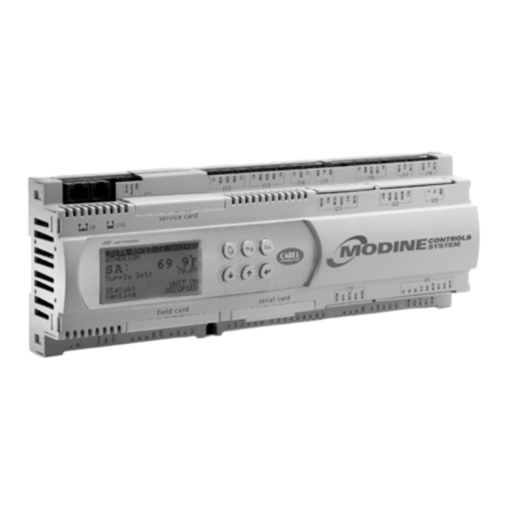
Page 7: Controller Overview
MODINE CONTROL SYSTEM MANUAL Models MPR & ERM Controller Overview Description and Features The Modine Control System utilizes a Carel programmable microprocessor controller. Highly advanced with a powerful microprocessor and fast processing speed, the controller features a high number of I/O’s for complex HVAC/R applications. The main controller board is housed in a plastic case that ensures a high index of protection and reduces the risk of electrostatic discharges due to incorrect handling. -
Page 8: Standard And Optional Sensors Monitored
MODINE CONTROL SYSTEM MANUAL Models MPR & ERM Standard and Optional Sensors Monitored The Modine Control System monitors a number of sensors within the Atherion unit as follows: Standard sensors monitored: • Supply Air (Field Installed – see main unit Installation Manual) Main DOAS –... -
Page 9: Pco 3 Controller Layout
MODINE CONTROL SYSTEM MANUAL Models MPR & ERM Controller Layout Reference Description Power supply connector [G (+), G0 (-)] Yellow power LED and 3 status LEDs Additional power supply for the terminal and 0 to 5 V ratiometric probes Universal analogue inputs: NTC, 0 to 1 V, 0 to 5 V ratiometric, 0 to 10 V, 0 to 20 mA, 4 to 20 mA Passive analog inputs: NTC, PT1000, ON/OFF 0 to 10 V analog outputs 24 Vac/Vdc digital inputs... -
Page 10: Display/Keypad Functions
MODINE CONTROL SYSTEM MANUAL Models MPR & ERM Display/Keypad Functions pGD1 Remote Display Keypad (Optional) Display Keypad Refer to Literature #MCP15-543 for installation instructions. Refer to the Board Settings section for instructions on programming the remote display keypad to the controller. Standard Buttons pGD1 Built-... -
Page 11: Menu Navigation
MODINE CONTROL SYSTEM MANUAL Models MPR & ERM Menu Navigation The following instructions refer to the built-in display keypad buttons. See the table on the previous page for the corresponding buttons if using the remote keypad. The Main Status Screen is displayed when the unit is first turned on or after one minute of keypad inactivity. From this Main Status Screen, eight sub menus can be accessed by pressing the button and using the buttons to move to the... -
Page 12: Password Protection
MODINE CONTROL SYSTEM MANUAL Models MPR & ERM Password Protection WARNING Improper control adjustments and manual mode control can cause property damage, injury or death. Read the installation, operating and maintenance instructions thoroughly before making adjustments. To prevent unauthorized adjustments, a password is required to gain access to certain menus. When a password is requested use the keys to enter the number and to access the page. -
Page 13: Main Menu - Tree Of Functions
MODINE CONTROL SYSTEM MANUAL Models MPR & ERM Main Menu – Tree of Functions Irrespective of the current screen displayed, pressing the key accesses the main menu, as shown below: Unit Status On/Off Unit On/Off By Display On/Off By pAD (Optional) Setpoints Supply Air Setpint Damper Min Position... -
Page 14: Main Status Screen
MODINE CONTROL SYSTEM MANUAL Models MPR & ERM Main Status Screen The Main Status Screen is displayed when the unit is first turned on or after one minute of keypad inactivity. The following information is displayed on the Main Status Screen: •... - Page 15 MODINE CONTROL SYSTEM MANUAL Models MPR & ERM Main Status Screen Parameters (continued) The status screens can be seen when the buttons are pressed on the main status screen. The following table describes the menu parameters (Note: Change in shading indicates change to next screen): PARAMETER DESCRIPTION FACTORY VALUE RANGE...
- Page 16 MODINE CONTROL SYSTEM MANUAL Models MPR & ERM Main Status Screen Parameters (continued) The status screens can be seen when the buttons are pressed on the main status screen. The following table describes the menu parameters (Note: Change in shading indicates change to next screen): PARAMETER DESCRIPTION FACTORY VALUE RANGE...
- Page 17 MODINE CONTROL SYSTEM MANUAL Models MPR & ERM Main Status Screen Parameters (continued) The status screens can be seen when the buttons are pressed on the main status screen. The following table describes the menu parameters (Note: Change in shading indicates change to next screen): PARAMETER DESCRIPTION FACTORY VALUE RANGE...
-
Page 18: On/Off Sub Menu
MODINE CONTROL SYSTEM MANUAL Models MPR & ERM On/Off Sub Menu Main Status Screen On/Off The following table describes the menu parameters (Note: Change in shading indicates change to next screen): PARAMETER DESCRIPTION FACTORY VALUE RANGE UNITS Unit Address Power By Display Actual Value On or Off... -
Page 19: Setpoint Sub Menu
MODINE CONTROL SYSTEM MANUAL Models MPR & ERM Setpoint Sub Menu Main Status Screen Setpoint The following table describes the menu parameters (Note: Change in shading indicates change to next screen): PARAMETER DESCRIPTION FACTORY VALUE RANGE UNITS Supply Air Setpoint 50-99 °F /°C Current Setpoint... - Page 20 MODINE CONTROL SYSTEM MANUAL Models MPR & ERM Setpoint Sub Menu (continued) Main Status Screen Setpoint The following table describes the menu parameters (Note: Change in shading indicates change to next screen): PARAMETER DESCRIPTION FACTORY VALUE RANGE UNITS Note: The Screen below will only be displayed if Damper Building Pressure Control is selected Building Pressure Setpoint 0-0.5...
- Page 21 MODINE CONTROL SYSTEM MANUAL Models MPR & ERM Setpoint Sub Menu (continued) Main Status Screen Setpoint The following table describes the menu parameters (Note: Change in shading indicates change to next screen): PARAMETER DESCRIPTION FACTORY VALUE RANGE UNITS Note: The Screen below will only be displayed if Exhaust Fan Constant Volume Control is selected Exhaust Fan Speed 1 100% ID15 and ID 16 Open...
-
Page 22: Clock/Scheduler Sub Menu
MODINE CONTROL SYSTEM MANUAL Models MPR & ERM Clock/Scheduler Sub Menu Main Status Screen Clock/Scheduler Note: The Schedule/Holidays can be used to either turn the unit On/Off or to Cycle the unit from Occupied to Unoccupied (when an Optional Space Sensor is installed). The following table describes the menu parameters (Note: Change in shading indicates change to next screen): PARAMETER DESCRIPTION FACTORY VALUE... -
Page 23: Input / Output Sub Menu
MODINE CONTROL SYSTEM MANUAL Models MPR & ERM Input / Output Sub Menu Analog Inputs: Main Status Screen Input/Output Analog Inputs The following table describes the menu parameters (Note: Change in shading indicates change to next screen): PARAMETER DESCRIPTION INPUT FACTORY VALUE RANGE... -
Page 24: Analog Outputs
MODINE CONTROL SYSTEM MANUAL Models MPR & ERM Input / Output Sub Menu (continued) Analog Outputs: Main Status Screen Input/Output Analog Outputs The following table describes the menu parameters (Note: Change in shading indicates change to next screen): PARAMETER DESCRIPTION OUTPUT FACTORY VALUE... -
Page 25: Data Logger Sub Menu
MODINE CONTROL SYSTEM MANUAL Models MPR & ERM Data Logger Sub Menu Main Status Screen Data Logger To access contents of the Data Logger menu simply press the button. The most recent alarm will be displayed on the screen. The upper bar will display the time and date of the most recent alarm. -
Page 26: Programming The Remote Display Keypad To The Controller
MODINE CONTROL SYSTEM MANUAL Models MPR & ERM Programming the Remote Display Keypad to the Controller In the situation that the terminal display address is required to be set up, the following procedure applies: Set the correct address on the display, connect to the controller and then power up the unit. By simultaneously pressing and holding , the display will show the Display Address screen. -
Page 27: Service Sub Menu
MODINE CONTROL SYSTEM MANUAL Models MPR & ERM Service Sub Menu Information Main Status Screen Service Information The following table describes the menu parameters (Note: Change in shading indicates change to next screen): PARAMETER DESCRIPTION FACTORY VALUE RANGE UNITS Code (Name of Program) Actual Value... -
Page 28: Working Hours
MODINE CONTROL SYSTEM MANUAL Models MPR & ERM Service Sub Menu (continued) Working Hours Main Status Screen Service Working Hours The following table describes the menu parameters (Note: Change in shading indicates change to next screen): PARAMETER DESCRIPTION FACTORY VALUE RANGE UNITS... -
Page 29: Bms Configuration
MODINE CONTROL SYSTEM MANUAL Models MPR & ERM Service Sub Menu (continued) BMS Configuration Main Status Screen Service BMS Configuration ( requires password PW1) The following table describes the menu parameters (Note: Change in shading indicates change to next screen): PARAMETER DESCRIPTION FACTORY VALUE RANGE... -
Page 30: Working Hour Setpoint
MODINE CONTROL SYSTEM MANUAL Models MPR & ERM Service Sub Menu (continued) Working Hour Setpoint Main Status Screen Service Service Settings Working Hour Setpoint ( requires password PW1) The following table describes the menu parameters (Note: Change in shading indicates change to next screen): PARAMETER DESCRIPTION FACTORY VALUE RANGE... -
Page 31: Control Settings
MODINE CONTROL SYSTEM MANUAL Models MPR & ERM Service Sub Menu (continued) Control Settings Main Status Screen Service Service Settings Control Settings ( requires password PW1) The following table describes the menu parameters (Note: Change in shading indicates change to next screen): PARAMETER DESCRIPTION FACTORY VALUE RANGE... - Page 32 MODINE CONTROL SYSTEM MANUAL Models MPR & ERM Service Sub Menu (continued) Control Settings (continued) Main Status Screen Service Service Settings Control Settings ( requires password PW1) The following table describes the menu parameters (Note: Change in shading indicates change to next screen): PARAMETER DESCRIPTION FACTORY VALUE RANGE...
- Page 33 MODINE CONTROL SYSTEM MANUAL Models MPR & ERM Service Sub Menu (continued) Control Settings (continued) Main Status Screen Service Service Settings Control Settings ( requires password PW1) The following table describes the menu parameters (Note: Change in shading indicates change to next screen): PARAMETER DESCRIPTION FACTORY VALUE RANGE...
- Page 34 MODINE CONTROL SYSTEM MANUAL Models MPR & ERM Service Sub Menu (continued) Control Settings (continued) Main Status Screen Service Service Settings Control Settings ( requires password PW1) The following table describes the menu parameters (Note: Change in shading indicates change to next screen): PARAMETER DESCRIPTION FACTORY VALUE RANGE...
- Page 35 MODINE CONTROL SYSTEM MANUAL Models MPR & ERM Service Sub Menu (continued) Control Settings (continued) Main Status Screen Service Service Settings Control Settings ( requires password PW1) The following table describes the menu parameters (Note: Change in shading indicates change to next screen): PARAMETER DESCRIPTION FACTORY VALUE RANGE...
- Page 36 MODINE CONTROL SYSTEM MANUAL Models MPR & ERM Service Sub Menu (continued) Control Settings (continued) Main Status Screen Service Service Settings Control Settings ( requires password PW1) The following table describes the menu parameters (Note: Change in shading indicates change to next screen): PARAMETER DESCRIPTION FACTORY VALUE RANGE...
- Page 37 MODINE CONTROL SYSTEM MANUAL Models MPR & ERM Service Sub Menu (continued) Control Settings (continued) Main Status Screen Service Service Settings Control Settings ( requires password PW1) The following table describes the menu parameters (Note: Change in shading indicates change to next screen): PARAMETER DESCRIPTION FACTORY VALUE RANGE...
- Page 38 MODINE CONTROL SYSTEM MANUAL Models MPR & ERM Service Sub Menu (continued) Control Settings (continued) Main Status Screen Service Service Settings Control Settings ( requires password PW1) The following table describes the menu parameters (Note: Change in shading indicates change to next screen): PARAMETER DESCRIPTION FACTORY VALUE RANGE...
-
Page 39: User Dev/Change Pw1
MODINE CONTROL SYSTEM MANUAL Models MPR & ERM Service Sub Menu (continued) Control Settings (continued) Main Status Screen Service Service Settings Control Settings ( requires password PW1) The following table describes the menu parameters (Note: Change in shading indicates change to next screen): PARAMETER DESCRIPTION FACTORY VALUE RANGE... -
Page 40: Manual Management
MODINE CONTROL SYSTEM MANUAL Models MPR & ERM Service Sub Menu (continued) Manual Management WARNING Improper control adjustments and manual mode control can cause property damage, injury or death. Read the installation, operating and maintenance instructions thoroughly before making adjustments. Manual Control Reset Main Status Screen ... -
Page 41: Digital Input
MODINE CONTROL SYSTEM MANUAL Models MPR & ERM Service Sub Menu (continued) Digital Input: Main Status Screen Service Manual Management Digital Input ( requires password PW1) The following table describes the menu parameters (Note: Change in shading indicates change to next screen): PARAMETER DESCRIPTION FACTORY VALUE RANGE... -
Page 42: Manufacturer Sub Menu
MODINE CONTROL SYSTEM MANUAL Models MPR & ERM Manufacturer Sub Menu Configuration Main Status Screen Manufacturer Configuration ( requires password PW2) The following table describes the menu parameters (Note: Change in shading indicates change to next screen). Do NOT make any changes to these settings without contacting the factory. - Page 43 MODINE CONTROL SYSTEM MANUAL Models MPR & ERM Manufacturer Sub Menu (continued) Configuration Main Status Screen Manufacturer Configuration ( requires password PW2) The following table describes the menu parameters (Note: Change in shading indicates change to next screen). Do NOT make any changes to these settings without contacting the factory.
- Page 44 MODINE CONTROL SYSTEM MANUAL Models MPR & ERM Manufacturer Sub Menu (continued) Configuration Main Status Screen Manufacturer Configuration ( requires password PW2) The following table describes the menu parameters (Note: Change in shading indicates change to next screen). Do NOT make any changes to these settings without contacting the factory.
- Page 45 MODINE CONTROL SYSTEM MANUAL Models MPR & ERM Manufacturer Sub Menu (continued) Configuration Main Status Screen Manufacturer Configuration ( requires password PW2) The following table describes the menu parameters (Note: Change in shading indicates change to next screen). Do NOT make any changes to these settings without contacting the factory.
- Page 46 MODINE CONTROL SYSTEM MANUAL Models MPR & ERM Manufacturer Sub Menu (continued) Configuration Main Status Screen Manufacturer Configuration ( requires password PW2) The following table describes the menu parameters (Note: Change in shading indicates change to next screen). Do NOT make any changes to these settings without contacting the factory.
- Page 47 MODINE CONTROL SYSTEM MANUAL Models MPR & ERM Manufacturer Sub Menu (continued) Configuration Main Status Screen Manufacturer Configuration ( requires password PW2) The following table describes the menu parameters (Note: Change in shading indicates change to next screen). Do NOT make any changes to these settings without contacting the factory.
- Page 48 MODINE CONTROL SYSTEM MANUAL Models MPR & ERM Manufacturer Sub Menu (continued) Configuration Main Status Screen Manufacturer Configuration ( requires password PW2) The following table describes the menu parameters (Note: Change in shading indicates change to next screen). Do NOT make any changes to these settings without contacting the factory.
- Page 49 MODINE CONTROL SYSTEM MANUAL Models MPR & ERM Manufacturer Sub Menu (continued) Configuration Main Status Screen Manufacturer Configuration ( requires password PW2) The following table describes the menu parameters (Note: Change in shading indicates change to next screen). Do NOT make any changes to these settings without contacting the factory.
- Page 50 MODINE CONTROL SYSTEM MANUAL Models MPR & ERM Manufacturer Sub Menu (continued) Configuration Main Status Screen Manufacturer Configuration ( requires password PW2) The following table describes the menu parameters (Note: Change in shading indicates change to next screen). Do NOT make any changes to these settings without contacting the factory.
-
Page 51: I/O Configuration - Digital Input Configuration
MODINE CONTROL SYSTEM MANUAL Models MPR & ERM Manufacturer Sub Menu (continued) I/O Configuration – Digital Input Configuration Main Status Screen Manufacturer I/O Configuration ( requires password PW2) The following table describes the menu parameters (Note: Change in shading indicates change to next screen). Do NOT make any changes to these settings without contacting the factory. - Page 52 MODINE CONTROL SYSTEM MANUAL Models MPR & ERM Manufacturer Sub Menu (continued) I/O Configuration – Digital Input Configuration Main Status Screen Manufacturer I/O Configuration ( requires password PW2) The following table describes the menu parameters (Note: Change in shading indicates change to next screen). Do NOT make any changes to these settings without contacting the factory.
- Page 53 MODINE CONTROL SYSTEM MANUAL Models MPR & ERM Manufacturer Sub Menu (continued) I/O Configuration – Digital Input Configuration Main Status Screen Manufacturer I/O Configuration ( requires password PW2) The following table describes the menu parameters (Note: Change in shading indicates change to next screen). Do NOT make any changes to these settings without contacting the factory.
- Page 54 MODINE CONTROL SYSTEM MANUAL Models MPR & ERM Manufacturer Sub Menu (continued) I/O Configuration – Digital Input Configuration Main Status Screen Manufacturer I/O Configuration ( requires password PW2) The following table describes the menu parameters (Note: Change in shading indicates change to next screen). Do NOT make any changes to these settings without contacting the factory.
- Page 55 MODINE CONTROL SYSTEM MANUAL Models MPR & ERM Manufacturer Sub Menu (continued) I/O Configuration – Digital Input Configuration Main Status Screen Manufacturer I/O Configuration ( requires password PW2) The following table describes the menu parameters (Note: Change in shading indicates change to next screen). Do NOT make any changes to these settings without contacting the factory.
-
Page 56: I/O Configuration - Analog Input Configuration
MODINE CONTROL SYSTEM MANUAL Models MPR & ERM Manufacturer Sub Menu (continued) I/O Configuration – Digital Input Configuration Main Status Screen Manufacturer I/O Configuration ( requires password PW2) The following table describes the menu parameters (Note: Change in shading indicates change to next screen). Do NOT make any changes to these settings without contacting the factory. - Page 57 MODINE CONTROL SYSTEM MANUAL Models MPR & ERM Manufacturer Sub Menu (continued) I/O Configuration – Analog Input Configuration Main Status Screen Manufacturer Analog Input Configuration ( requires password PW2) The following table describes the menu parameters (Note: Change in shading indicates change to next screen). Do NOT make any changes to these settings without contacting the factory.
- Page 58 MODINE CONTROL SYSTEM MANUAL Models MPR & ERM Manufacturer Sub Menu (continued) I/O Configuration – Analog Input Configuration Main Status Screen Manufacturer Analog Input Configuration ( requires password PW2) The following table describes the menu parameters (Note: Change in shading indicates change to next screen). Do NOT make any changes to these settings without contacting the factory.
- Page 59 MODINE CONTROL SYSTEM MANUAL Models MPR & ERM Manufacturer Sub Menu (continued) I/O Configuration – Analog Input Configuration Main Status Screen Manufacturer Analog Input Configuration ( requires password PW2) The following table describes the menu parameters (Note: Change in shading indicates change to next screen). Do NOT make any changes to these settings without contacting the factory.
- Page 60 MODINE CONTROL SYSTEM MANUAL Models MPR & ERM Manufacturer Sub Menu (continued) I/O Configuration – Analog Input Configuration Main Status Screen Manufacturer Analog Input Configuration ( requires password PW2) The following table describes the menu parameters (Note: Change in shading indicates change to next screen). Do NOT make any changes to these settings without contacting the factory.
- Page 61 MODINE CONTROL SYSTEM MANUAL Models MPR & ERM Manufacturer Sub Menu (continued) I/O Configuration – Analog Input Configuration Main Status Screen Manufacturer Analog Input Configuration ( requires password PW2) The following table describes the menu parameters (Note: Change in shading indicates change to next screen). Do NOT make any changes to these settings without contacting the factory.
- Page 62 MODINE CONTROL SYSTEM MANUAL Models MPR & ERM Manufacturer Sub Menu (continued) I/O Configuration – Analog Input Configuration Main Status Screen Manufacturer Analog Input Configuration ( requires password PW2) The following table describes the menu parameters (Note: Change in shading indicates change to next screen). Do NOT make any changes to these settings without contacting the factory.
-
Page 63: I/O Configuration - Relay Output Configuration
MODINE CONTROL SYSTEM MANUAL Models MPR & ERM Manufacturer Sub Menu (continued) I/O Configuration – Analog Input Configuration Main Status Screen Manufacturer Analog Input Configuration ( requires password PW2) The following table describes the menu parameters (Note: Change in shading indicates change to next screen). Do NOT make any changes to these settings without contacting the factory. - Page 64 MODINE CONTROL SYSTEM MANUAL Models MPR & ERM Manufacturer Sub Menu (continued) I/O Configuration – Relay Output Configuration Main Status Screen Manufacturer Relay Output Configuration ( requires password PW2) The following table describes the menu parameters (Note: Change in shading indicates change to next screen). Do NOT make any changes to these settings without contacting the factory.
- Page 65 MODINE CONTROL SYSTEM MANUAL Models MPR & ERM Manufacturer Sub Menu (continued) I/O Configuration – Relay Output Configuration Main Status Screen Manufacturer Relay Output Configuration ( requires password PW2) The following table describes the menu parameters (Note: Change in shading indicates change to next screen). Do NOT make any changes to these settings without contacting the factory.
-
Page 66: I/O Configuration - Analog Output Configuration
MODINE CONTROL SYSTEM MANUAL Models MPR & ERM Manufacturer Sub Menu (continued) I/O Configuration – Analog Output Configuration Main Status Screen Manufacturer Analog Output Configuration ( requires password PW2) The following table describes the menu parameters (Note: Change in shading indicates change to next screen). Do NOT make any changes to these settings without contacting the factory. -
Page 67: Erm
MODINE CONTROL SYSTEM MANUAL Models MPR & ERM Manufacturer Sub Menu (continued) I/O Configuration – Analog Output Configuration Main Status Screen Manufacturer Analog Output Configuration ( requires password PW2) The following table describes the menu parameters (Note: Change in shading indicates change to next screen). Do NOT make any changes to these settings without contacting the factory. - Page 68 MODINE CONTROL SYSTEM MANUAL Models MPR & ERM Manufacturer Sub Menu (continued) Main Status Screen Manufacturer ERM (if ERM is enabled) ( requires password PW2) The following table describes the menu parameters (Note: Change in shading indicates change to next screen). Do NOT make any changes to these settings without contacting the factory.
- Page 69 MODINE CONTROL SYSTEM MANUAL Models MPR & ERM Manufacturer Sub Menu (continued) Main Status Screen Manufacturer ERM (if ERM is enabled) ( requires password PW2) The following table describes the menu parameters (Note: Change in shading indicates change to next screen). Do NOT make any changes to these settings without contacting the factory.
-
Page 70: Initialization
MODINE CONTROL SYSTEM MANUAL Models MPR & ERM Manufacturer Sub Menu (continued) Initialization Main Status Screen Manufacturer Initialization ( requires password PW2) The following table describes the menu parameters (Note: Change in shading indicates change to next screen). Do NOT make any changes to these settings without contacting the factory. - Page 71 MODINE CONTROL SYSTEM MANUAL Models MPR & ERM Manufacturer Sub Menu (continued) pAD Settings Main Status Screen Manufacturer pAD Settings (if pAD is enabled) ( requires password PW2) The following table describes the menu parameters (Note: Change in shading indicates change to next screen). Do NOT make any changes to these settings without contacting the factory.
- Page 72 MODINE CONTROL SYSTEM MANUAL Models MPR & ERM Manufacturer Sub Menu (continued) pAD Settings Main Status Screen Manufacturer pAD Settings (if pAD is enabled) ( requires password PW2) The following table describes the menu parameters (Note: Change in shading indicates change to next screen). Do NOT make any changes to these settings without contacting the factory.
-
Page 73: Evo -Evd Settings (Electronic Expansion Valve Driver)
MODINE CONTROL SYSTEM MANUAL Models MPR & ERM Manufacturer Sub Menu (continued) EVO -EVD Settings (Electronic Expansion Valve Driver) Main Status Screen Manufacturer EVO -EVD Settings (if in CDSS mode) ( requires password PW2) The following table describes the menu parameters (Note: Change in shading indicates change to next screen). Do NOT make any changes to these settings without contacting the factory. - Page 74 MODINE CONTROL SYSTEM MANUAL Models MPR & ERM Manufacturer Sub Menu (continued) EVO -EVD Settings (Electronic Expansion Valve Driver) Main Status Screen Manufacturer EVO -EVD Settings (if in CDSS mode) ( requires password PW2) The following table describes the menu parameters (Note: Change in shading indicates change to next screen). Do NOT make any changes to these settings without contacting the factory.
- Page 75 MODINE CONTROL SYSTEM MANUAL Models MPR & ERM Manufacturer Sub Menu (continued) EVO -EVD Settings (Electronic Expansion Valve Driver) Main Status Screen Manufacturer EVO -EVD Settings (if in CDSS mode) ( requires password PW2) The following table describes the menu parameters (Note: Change in shading indicates change to next screen). Do NOT make any changes to these settings without contacting the factory.
- Page 76 MODINE CONTROL SYSTEM MANUAL Models MPR & ERM Manufacturer Sub Menu (continued) EVO -EVD Settings (Electronic Expansion Valve Driver) Main Status Screen Manufacturer EVO -EVD Settings (if in CDSS mode) ( requires password PW2) The following table describes the menu parameters (Note: Change in shading indicates change to next screen). Do NOT make any changes to these settings without contacting the factory.
- Page 77 MODINE CONTROL SYSTEM MANUAL Models MPR & ERM Manufacturer Sub Menu (continued) EVO -EVD Settings (Electronic Expansion Valve Driver) Main Status Screen Manufacturer EVO -EVD Settings (if in CDSS mode) ( requires password PW2) The following table describes the menu parameters (Note: Change in shading indicates change to next screen). Do NOT make any changes to these settings without contacting the factory.
-
Page 78: Digital Scroll Compressors
MODINE CONTROL SYSTEM MANUAL Models MPR & ERM Digital Scroll Compressors Starting Frequency and Minimum Compressor Running Time The following default values are used for compressor protection: • Compressor minimum run-time: 2 minutes (This time is required to ensure adequate oil return and sufficient motor cooling from the suction gas upon start-up of the compressor.) •... -
Page 79: Electronic Expansion Valves Carel Cdss Mode
MODINE CONTROL SYSTEM MANUAL Models MPR & ERM Electronic Expansion Valves Carel CDSS Mode (See Emerson EC3 Manual for EC3 Mode) The electronic expansion valve enables correct metering of refrigerant. The valve uses both a pressure transducer and temperature probe to ensure that the superheat of the refrigeration system remains correct. -
Page 80: Unit Alarms
MODINE CONTROL SYSTEM MANUAL Models MPR & ERM Unit Alarms Alarm Cause Action Indicates an error with the real Once the clock returns to time clock on-board the functioning correctly the alarm • • Clock board fault or not connected controller. - Page 81 MODINE CONTROL SYSTEM MANUAL Models MPR & ERM Unit Alarms (continued) Alarm Cause Action The unit is calling for Gas heat Alarm is generated – No other • Gas Valve 1 but the main gas valve has not action taken.
- Page 82 MODINE CONTROL SYSTEM MANUAL Models MPR & ERM Unit Alarms (continued) Alarm Cause Action Note: The following applies only to units with an Energy Recovery Section with a pCOxs controller ERM humidity sensor is either Alarm generated – no other •...
-
Page 83: Main Unit Controller Inputs/Outputs
MODINE CONTROL SYSTEM MANUAL Models MPR & ERM Main Unit Controller Inputs/Outputs Inputs The inputs of the controller are listed below. Note that some items are optional and may not be installed on all models. Input Type Input # Voltage Description Notes Analog... -
Page 84: Pco Outputs
MODINE CONTROL SYSTEM MANUAL Models MPR & ERM Main Unit Controller Inputs/Outputs (continued) Outputs The outputs of the controller are listed below. Note that some items are optional and may not be installed on all models. Output Type Output # Voltage Description Notes... -
Page 85: Pcoe Expansion Module Inputs/Outputs (For Emerson Ec3 Superheat Control Only)
MODINE CONTROL SYSTEM MANUAL Models MPR & ERM Main Unit Controller Inputs/Outputs (continued) pCOe Expansion Module Inputs/Outputs (for Emerson EC3 Superheat Control only) The inputs/outputs of the controller are listed below. Note that some items are optional and may not be installed on all models. NOTE: This is NOT used in CDSS Mode. -
Page 86: Energy Recovery Module Controller Inputs/Outputs (If Equipped)
MODINE CONTROL SYSTEM MANUAL Models MPR & ERM Energy Recovery Module Controller Inputs/Outputs (if equipped) pCOxs Inputs The inputs of the controller are listed below. Note that some items are optional and may not be installed on all models. Input Type Input # Voltage pCOxs Expansion Module... -
Page 87: Typical Bms - Ems - Bas System Variables
MODINE CONTROL SYSTEM MANUAL Models MPR & ERM Typical BMS – EMS – BAS System Variables Carel Side BMS Side Carel Read/ Data Description Variable Name BACNet LonWorks SNVT Index Write Type Return Air Ret_Air_Hum Humidity Space pAD_Temperature1 nvoSpaceTemp temp_p Temperature Building Build_Press... - Page 88 MODINE CONTROL SYSTEM MANUAL Models MPR & ERM Typical BMS – EMS – BAS System Variables (continued): Carel Side BMS Side Carel Read/ Data Description Variable Name BACNet LonWorks SNVT Index Write Type Suction Pressure LP_Sp AV21 Setpoint ERM Entering (True Outside) Ent_Hum AV22...
- Page 89 MODINE CONTROL SYSTEM MANUAL Models MPR & ERM Typical BMS – EMS – BAS System Variables (continued): Carel Side BMS Side Carel Read/ Data Description Variable Name BACNet LonWorks SNVT Index Write Type Space Humidity pAD_hum AV1001 nvoSpaceHum count Space Humidity pAD_Setp_Humid AV1002 nvo/nviSpaceHumSet...
- Page 90 MODINE CONTROL SYSTEM MANUAL Models MPR & ERM Typical BMS – EMS – BAS System Variables (continued): Carel Side BMS Side Carel Read/ Data Description Variable Name BACNet LonWorks SNVT Index Write Type Enthalpy Lockout 0= None, 1= Comp Enthalpy_Lockout AV1022 1, 2= Comp 2, 3= Comp 1 and...
- Page 91 MODINE CONTROL SYSTEM MANUAL Models MPR & ERM Typical BMS – EMS – BAS System Variables (continued): Carel Side BMS Side Carel Read/ Data Description Variable Name BACNet LonWorks SNVT Index Write Type High Pressure HP_sw nvoHPSwitch switch Switch Low Pressure LP_sw nvoLPSwitch switch...
- Page 92 MODINE CONTROL SYSTEM MANUAL Models MPR & ERM Typical BMS – EMS – BAS System Variables (continued): Carel Side BMS Side Carel Read/ Data Description Variable Name BACNet LonWorks SNVT Index Write Type Outside Air Damper oa_damper_open BV23 Opening Outside Air oa_damper_close BV24 Damper Closing...
- Page 93 MODINE CONTROL SYSTEM MANUAL Models MPR & ERM Typical BMS – EMS – BAS System Variables (continued): Carel Side BMS Side Carel Read/ Data Description Variable Name BACNet LonWorks SNVT Index Write Type ERM Filter Switch (Supply ERV_Filter_SW BV43 or Return) ERM Exhaust Fan Status ERV_Exh_Fan_Stat...
- Page 94 MODINE CONTROL SYSTEM MANUAL Models MPR & ERM Typical BMS – EMS – BAS System Variables (continued): Carel Side BMS Side Carel Read/ Data Description Variable Name BACNet LonWorks SNVT Index Write Type Digital Compressor mDCS_AL BV61 Switch Alarm Exhaust Fan Exhaust_Fan_Switch BV62 Status Switch...
- Page 95 MODINE CONTROL SYSTEM MANUAL Models MPR & ERM MCP15-525.0...
- Page 96 Modine Manufacturing Company has a continuous product improvement program, and therefore reserves the right to change design and specifications without notice. Commercial Products Group • Modine Manufacturing Company • 1500 DeKoven Avenue • Racine, Wisconsin, USA 53403 Phone: 1.800.828.4328 (HEAT) • www.modinehvac.com MCP15-525.0...
Need help?
Do you have a question about the Atherion MPR and is the answer not in the manual?
Questions and answers