
Related Manuals for Hydac MFU-60E


Summary of Contents for Hydac MFU-60E
- Page 1 MobileFiltration Unit MFU-60E MFU-100E Operating instructions 4712570a / 2024-10...
- Page 2 © 2024 HYDAC Filter Systems GmbH. All rights reserved. ® All product names used may be trademarks or registered trademarks of HYDAC or the particular owner. This manual was prepared to the best of our knowledge. Nevertheless and despite the greatest care, it cannot be excluded that mistakes could have crept in.
-
Page 3: Table Of Contents
TABLE OF CONTENTS Table of Contents General ........................... Target group of the manual ................Illustrations in the manual................... 1.2.1 Depiction of warning signs..............1.2.2 Representation of requirements ............1.2.3 Representation of procedural instructions ..........1.2.4 Representation of intermediate results/results ........1.2.5 Supplementary symbols ............... - Page 4 TABLE OF CONTENTS Operation ........................Switching the filter unit on or off/EMERGENCY-STOP ........Observing clogging indicators ................Selecting the operating modes ................6.3.1 Recirculation with filtration/dewatering ..........6.3.2 Recirculation without filtration............... Operation with accessories ................6.4.1 Using a suction line filter on the suction hose ........Rectifying malfunctions ....................
-
Page 5: General
1. GENERAL General 54043196243574411 Before you use this product for the first time, read this manual at least up to the chapter "Operation". If you would like to carry out maintenance or troubleshooting, you can find the procedure in the respective chapters. The use and the handling of the product as well as its use are not self-explanatory and are described in detail in this manual. - Page 6 1. GENERAL Warnings visually highlighted in boxes Warnings visually highlighted in boxes provide the following information in connection with a hazard: DANGER High electrical voltages Life-threatening injury or death! Disconnect the system from the power supply and secure it against being switched back on again. Warning level Type and source of the hazard How high is the risk...
-
Page 7: Representation Of Requirements
1. GENERAL Warning level What this means for you Warns of dangers for people with a high risk potential. DANGER Failure to observe this warning is highly likely to result in serious injury or even death. Warns of dangers for people with a medium risk potential. WARNING Failure to observe this warning may result in serious injury or even death. -
Page 8: Representation Of Intermediate Results/Results
For the warranty provided by us, please refer to our terms of delivery. They are made available to you at the conclusion of the contract at the latest. They can also be found at www.hydac.com -> General Terms and Conditions. Notes on copyright 54043195578747019 All copyrights for this manual lies with the manufacturer. -
Page 9: Safety Information
2. SAFETY INFORMATION Safety information 81064793553088523 The product is designed as safe. In spite of that, there is danger in some actions that can only be avoided by using the right procedures. These correct procedures and points, which must be followed, are described in this manual. - Page 10 2. SAFETY INFORMATION These instructions are intended for: Activity Personnel Knowledge Transport, Specialist Knowledge of transport safety is required storage personnel – General Installation Specialist Safe handling/use of tools. personnel – Laying and connecting hydraulic pipe and Mechanical hose lines and connections. Laying and connecting electrical cables, electrical machines and sockets.
- Page 11 2. SAFETY INFORMATION Activity Personnel Knowledge Troubleshooting, Specialist Safe handling/use of tools. maintenance, personnel – Product-specific knowledge is required. decommissioning, Mechanical disassembly Specialist personnel – Electrical Disposal Specialist Knowledge of environmentally friendly personnel – disposal of materials, auxiliary and oper- General ating materials is required.
-
Page 12: Hazard Symbols/Pictograms
2. SAFETY INFORMATION Hazard symbols/pictograms 81064793449661195 The following safety signs / pictograms can be found in this manual. They indicate specific dangers to persons, property or to the surroundings. Observe these safety signs / pictograms and act with particular caution in such cases. Always keep all safety signs / pictograms complete and legible. - Page 13 2. SAFETY INFORMATION Hazardous to the environment Others symbols used These marks can be found for all safety and warning instructions in this manual which indicate a particular danger to persons, property or the environment. Exposed electrical components Danger due to operating pressure Signs used for the required specialist personnel These symbols show the required training/knowledge for installation work and/or main- tenance work.
-
Page 14: Danger Notifications
2. SAFETY INFORMATION Danger notifications 81064793449592971 The following dangers can occur in the various life cycles of the product: Life cycle – in all life cycles. The following risks could arise during all life cycles: DANGER Electric voltage warning Danger of fatal injury In case of any damage to the insulation, switch off the supply voltage immediately and arrange for repairs to be carried out. - Page 15 2. SAFETY INFORMATION Life cycle – maintenance / troubleshooting The following dangers can arise in the maintenance / troubleshooting life cycles: CAUTION Spraying operating fluid when venting the filter housing Eye injury Wear safety goggles. 15 / 72 4712570a / 2024-10...
-
Page 16: Safety Marking
2. SAFETY INFORMATION Safety marking 54043195796432267 The following safety markings, labels/signs are provided on the product. The labels/signs on the product must always be easy to read. Fig. 1: Safety marking, label/sign on the product Label Name plate with the manufacturer's address, for details, see ▶Sec. 3.5 "Decoding the name plate"... -
Page 17: Observing Regulatory Information
2. SAFETY INFORMATION Observing regulatory information 9007199302626571 Observe the following regulatory information and directives: ● Legal and local regulations for accident prevention ● Legal and local regulations for environmental protection and environmental require- ments ● Country-specific regulations, organisation-specific regulations ● Occupational safety rules Observing environmental precautions 63050395051134859... -
Page 18: Product And Technical Specifications
3. PRODUCT AND TECHNICAL SPECIFICATIONS Product and technical specifications 90071992625945611 The power units of the MobileFiltration Unit MFU-30/60/100 series are used as mobile service units for filling hydraulic systems, flushing small hydraulic systems and for cleaning in bypass flow. Unfiltered draining is also possible. Solid particle contamination and free water can be removed by the filter elements. -
Page 19: Checking The Scope Of Supply
Here you will find the scope of supply for the product. ● Check the packaging and the product for damage. Report any damage in transit to the forwarding agent or the HYDAC department in charge. ● Check the scope of supply for completeness. -
Page 20: Improper Use Or Use Deviating From Intended Use
54043195607009803 Any other use or extended use shall not be considered intended use. HYDAC FILTER SYSTEMS GMBH will assume no liability for any damage resulting from such use. This risk is borne solely by the owner. Improper use can result in hazards and/or the unit can be damaged. Examples of improper use include: ●... -
Page 21: Technical Data
3. PRODUCT AND TECHNICAL SPECIFICATIONS Technical Data 81064793370867467 If you are aware of the technical data of the product, you will be able to use it optimally. This chapter provides the technical data of the product: MFU-60 MFU-100 Nominal flow rate ≈ 60 l/min ≈ 100 l/min Empty weight... - Page 22 3. PRODUCT AND TECHNICAL SPECIFICATIONS MFU-60 MFU-100 Sealing material Permitted fluid temperature range -10 … 80°C Permitted ambient temperature range -10 … 40°C Permitted storage temperature range 0 … 60°C Permitted air humidity during storage ≤ 90% relative humidity, non-condensing Permitted air during storage Clean, salt-free air, not near oxidising substances (rust film) Storage duration Unlimited.
-
Page 23: Decoding The Name Plate
63050394863872267 Details for identifying the product are found on the name plates on the product as well as their components. Always mention the part number and the serial number when contacting HYDAC. Fig. 2: Decoding the name plate 23 / 72 4712570a / 2024-10... - Page 24 3. PRODUCT AND TECHNICAL SPECIFICATIONS Name plate of the filter unit Name plate of electric motor Model Filter unit model code, for details see ▶Sec. 3.5.1 "Model code" Part number Serial number Date Year/month of production Voltage [V] / Grid [Ph] Voltage/Power supply Weight [kg] Empty weight...
-
Page 25: Model Code
3. PRODUCT AND TECHNICAL SPECIFICATIONS 3.5.1 Model code 9007201777303691 The model code is composed of the following: MFU - 60 P 34 - S N - F ED / -CD-M1 Series MobileFiltration Unit MFU = Size 30 l/min 60 l/min 100 l/min Type Economy... -
Page 26: Dimensions And Hydraulic Diagram
3. PRODUCT AND TECHNICAL SPECIFICATIONS Dimensions and hydraulic diagram 72057594119095819 The dimensions and hydraulic diagrams of the various product variants can be found below. Check the model code on the name plate of the filter unit. Fig. 4: Dimensions (all specifications are in mm) 26 / 72 4712570a / 2024-10... -
Page 27: Fig. 5 Hydraulic Diagram
3. PRODUCT AND TECHNICAL SPECIFICATIONS Differential pressure indicator 4000 Main switch Inlet Required space for removing the filter element Outlet Hydraulic diagram Inlet Outlet Bleeding Drain BP1 / Clogging indicator 1430 BP2 / Differential pressure indicator 2600 HQ1 / Strainer 3250 HQ2 / Filter housing... -
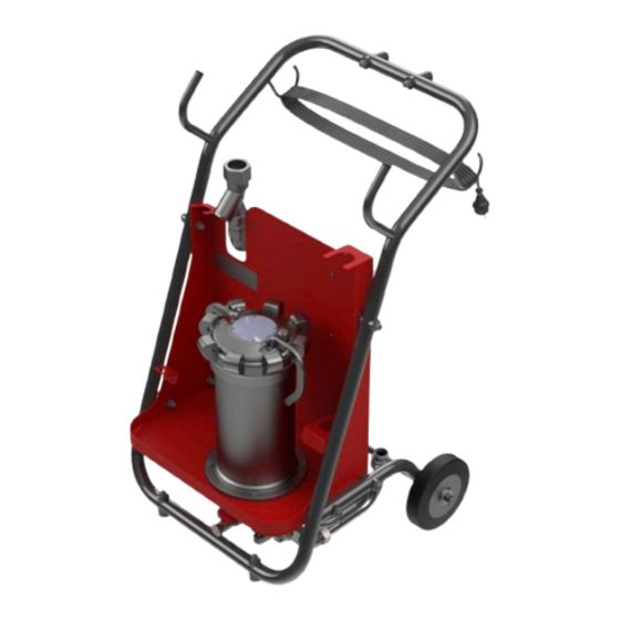
Page 28: Components And Operating Parts
3. PRODUCT AND TECHNICAL SPECIFICATIONS Components and operating parts 72057594116542987 The following components/operating elements can be found on the filter unit: Fig. 6: Components 28 / 72 4712570a / 2024-10... - Page 29 3. PRODUCT AND TECHNICAL SPECIFICATIONS Clogging indicator, visual Differential pressure indicator, visual Pump End cap lever Strainer Filter housing Electric motor Inlet Outlet Air vent Drain Type label 1110 Tube frame 1111 Sheet console 1112 Gear 1400 End cap 3400 Hose assembly 4000 Main switch...
-
Page 30: Transportation And Storage
4. TRANSPORTATION AND STORAGE Transportation and storage 72057594117729675 You will find the respective notice on the prevention of damage to the product during transport or storage in this chapter. Empty the filter unit fully before transporting it or putting it into storage. Remove and dispose of the used filter element and clean the inside of the filter bowl. -
Page 31: Transporting/Storing The Filter Unit With Hoses And Lances
4. TRANSPORTATION AND STORAGE Transporting/storing the filter unit with hoses and lances 54043195609098123 Insert both the lances into the holders for that purpose on the filter unit from the top. Fig. 9: Transportation/Storage with hoses 31 / 72 4712570a / 2024-10... -
Page 32: Setting Up/Assembly/Integration Of The Filter Unit
5. SETTING UP/ASSEMBLY/INTEGRATION OF THE FILTER UNIT Setting up/assembly/integration of the filter unit 90071992627224587 An optimally assembled and installed product ensures a safe and continuous operation. Avoiding siphoning 72057594101524491 If there is a height difference ΔH between the suction side and pressure side container/system, the low lying line can develop a suction effect and trigger the... -
Page 33: Making The Electrical Connections
5. SETTING UP/ASSEMBLY/INTEGRATION OF THE FILTER UNIT If different oils are mixed, the oil properties can change negatively as follows: ● Higher risk of cavitation ● More seal wear ● Modified anti-wear properties ● Poorer filterability ● Reduced filter element service lives ●... -
Page 34: Filter Unit Without Power Plug/Without Single-Ended Cordset
5. SETTING UP/ASSEMBLY/INTEGRATION OF THE FILTER UNIT 5.3.1 Filter unit without power plug/without single-ended cordset 36028797280244235 Depending on the version, the filter unit has neither a power plug nor a single-ended cordset. Connect up the filter unit with a suitable single-ended cordset and/or power plug. DANGER Electric voltage warning Danger of fatal injury... -
Page 35: Connecting The Suction/Pressure Port
5. SETTING UP/ASSEMBLY/INTEGRATION OF THE FILTER UNIT Connect the unit according to the following steps: 1. Remove the power supply cable from its bracket and unwind it completely. 2. Before inserting the power plug, ensure that the main switch is in the 0 or OFF position. - Page 36 5. SETTING UP/ASSEMBLY/INTEGRATION OF THE FILTER UNIT Example: The mineral oil-based hydraulic oil has a This formula applies to straight pipe runs. Particularly with regard density of ≈ 0.9 kg/dm³ to the suction side connection, note that additional connectors and pipe bends increase the pressure difference.
-
Page 37: Attaching/Connecting The Suction/Pressure Hoses (Accessories)
5. SETTING UP/ASSEMBLY/INTEGRATION OF THE FILTER UNIT Attaching/connecting the suction/pressure hoses (accessories) 45035996354529419 The suction/pressure hoses from the filter unit ▶Sec. 10.2.2 "Accessories list" are matched to the filter unit. If you use different connection hoses, take into account the pressure loss when connecting suction/pressure hoses. The IN / OUT connection dimensions on the filter unit can be found in chapter ▶Sec. 3.4 "Technical Data". -
Page 38: Commissioning The Filter Unit
5. SETTING UP/ASSEMBLY/INTEGRATION OF THE FILTER UNIT Commissioning the filter unit 54043195609216139 If the following points have been checked and are answered with OK, then the filter unit is ready for operation. 1. Install the a filter element in the filter bowl. 2. -
Page 39: Operation
6. OPERATION Operation 90071992626515467 Select the desired operating mode as described in chapter ▶Sec. 6.3 "Selecting the operating modes". Connect the suction port/pressure port to the containers to be cleaned and switch the filter unit on at the main switch. To monitor the service life of filter element, the filter unit is equipped with clogging indi- cators. -
Page 40: Selecting The Operating Modes
6. OPERATION Selecting the operating modes 72057594117080075 You will find further details on the operating methods in the chapters below. In this context, ensure that: ● The suction hose suctions as close to the bottom of the container as possible, however not directly at the base. ●... -
Page 41: Recirculation Without Filtration
6. OPERATION 6.3.2 Recirculation without filtration 72057594117095307 For the Circulation without filtration operating mode, remove the filter element. Fig. 14: Example of application: Recir- culation ü The filter element has been removed from the filter unit. 1. Connect the suction hose to the oil tank/container and fit the suction hose in it and also secure it against falling out. -
Page 42: Operation With Accessories
6. OPERATION Operation with accessories 45035996536196235 In order to adapt the filter unit to your requirements, you can select some items from the accessories list. While using accessories, the technical framework conditions can change in some cases such as the maximum permissible viscosity short time duty instead of continuous operation, etc. -
Page 43: Rectifying Malfunctions
The is no power to the Check the feed line to electric motor. the filter unit. Replace them if necessary. The electric motor/ Contact HYDAC pump is defective. Service. The transport locks are Remove the transport still mounted. seals. The transport seals are the yellow plastic parts. -
Page 44: Tab. 6 Error/Cause/Rectification
7. RECTIFYING MALFUNCTIONS Error Cause(s) Remedy Filter element is The fluid is heavily Replace the filter clogged. contaminated. element. The clogging indicator The contamination is responding. retention capacity of the filter element has been reached. The viscosity of the Check the viscosity of fluid is too high. -
Page 45: Performing Maintenance
8. PERFORMING MAINTENANCE Performing maintenance 90071992627226507 For a long, trouble-free service life of the product, regular maintenance activities are required. This chapter contains the description of the required maintenance activities and the qualifications of the staff needed to carry out these tasks. WARNING The hydraulic system is under operating pressure Danger of bodily injury... -
Page 46: Fig. 15 Operating The Filter Bowl Cover
8. PERFORMING MAINTENANCE cator. If the differential pressure exceeds the admissible Δp of the filter element, the element may be destroyed. Monitor and change the filter element regularly. The filter element can be changed without tool. There are two end cap levers with different functions in the end cap of the filter housing. - Page 47 8. PERFORMING MAINTENANCE 5. Keep the container (e) ready to collect the operating fluid. 6. Empty the filter housing completely, unscrew the protective cap and open the ball valve (f). Collect the escaping operating fluid with a suitable container. Return the collected oper- ating fluid in the dirt tank.
- Page 48 8. PERFORMING MAINTENANCE 10. Use the clamp to remove the used filter element from the filter housing. Dispose of the used filter element as well as the remaining oil volume in an environmentally friendly manner. 11. Install the new filter element in the filter bowl.
- Page 49 8. PERFORMING MAINTENANCE 15. Turn the end cap anticlockwise up to the stop. 16. Press the end cap lever without locking pin fully in a downward direction. 17. Close the drain ball valve DRAIN of the filter bowl and screw on the protective cap.
- Page 50 8. PERFORMING MAINTENANCE 19. If the filter housing is vented, then the operating fluid escapes from the vent valve. Close the end cap lever, the vent valve is closed and the locking pin snaps in place. 20. Remove and dispose of the escaping operating fluid in an environmentally friendly manner.
-
Page 51: Removing/Installing The Protective Screen
8. PERFORMING MAINTENANCE Removing/installing the protective screen 63050394863350923 The installed protective screen protects the pump from coarse contamination which could cause damage. If the uptake capacity of the protective screen has been reached, the volumetric flow through the filter unit reduces sharply. Clean the protective screen regularly. - Page 52 8. PERFORMING MAINTENANCE CAUTION Sharp-edged metallic chips/metallic particles in the protective screen Danger of cuts/eye injuries when reaching in or blowing out Wear protective gloves. Wear safety goggles. NOTICE Damaged protective screen The filter unit will be damaged/destroyed Never operate the filter unit with a damaged or defective protective screen. If the delivery of the pump drops or if the pump's noise level increases, then check/ clean the protective screen.
-
Page 53: Checking And Cleaning The Ventilation Hole
8. PERFORMING MAINTENANCE Checking and cleaning the ventilation hole 5141954955 The ventilation hole is used for deaerating the filter housing. If the pressure in the filter housing does not reduce after opening the cover handle, the vent hole is blocked. CAUTION Spraying operating fluid when venting the filter housing Eye injury... -
Page 54: Decommissioning/Disposal
9. DECOMMISSIONING/DISPOSAL Decommissioning/Disposal 99079191859273099 In the following chapters, you will be provided with information regarding temporary shutdown/final decommissioning and disposal of the product. Temporary shutdown 253902219 If the product is being temporarily shut down, the following measures are adequate: 1. Switch the product off and disconnect it from all sources of energy. 2. -
Page 55: Appendix
Contact details such as the telephone numbers, e-mail and mailing addresses for the Hotline, product support, Customer Service, branch offices, service partners for mainte- nance, repair and spare parts can be found on our homepage www.hydac.com. HYDAC SYSTEMS & SERVICES GMBH Friedrichsthaler Str. -
Page 56: 10.2 Finding Spare Parts/Accessories
10. APPENDIX 10.2 Finding spare parts/accessories 81064793372525067 Use only original spare parts for a long and defect-free life cycle of the product. When ordering spare parts and accessories make sure to always indicate the exact model code and the serial number. The following spare parts are available for your selection: Fig. 17: Spare parts drawing Item Qty. -
Page 57: 10.2.1 Finding The Filter Elements
10. APPENDIX Item Qty. Designation Part no. 2600 Clogging indicator Differential pressure indicator 303197 3100 Vane pump 30 l/min 3051015 3100 Vane pump 60 l/min 721653 3100 Vane pump 100 l/min 722546 3110 Electric motor for rotary MFU-30(60)Sxx-Sx-FED vane pumps (400V) 3110 Electric motor for rotary... -
Page 58: Tab. 8 Filter Elements N50Dmxxx
10. APPENDIX Item Qty. Designation Materi Part no. Filter element 10 µm, N50DM010-F 3944988 DIMICRON Filter element 20 µm, N50DM020-F 3944989 DIMICRON Tab. 8: Filter elements N50DMxxx Filter elements N50AMxxx AQUAMICRON Item Qty. Designation Materi Part no. Filter element 2 µm, N50AM002-F 4728566 AQUAMICRON Filter element 5 µm, N50AM005-F 4728567... -
Page 59: Tab. 11 Filter Elements N100Amxxx
10. APPENDIX Filter elements N100AMxxx AQUAMICRON Item Qty. Designation Materi Part no. Filter element 2 µm, N100AM002-F 4728570 AQUAMICRON Filter element 5 µm, N100AM005-F 4728571 AQUAMICRON Filter element 10 µm, N100AM010-F 4728572 AQUAMICRON Filter element 20 µm, N100AM020-F 4728573 AQUAMICRON Tab. 11: Filter elements N100AMxxx 59 / 72 4712570a / 2024-10... -
Page 60: 10.2.2 Accessories List
10. APPENDIX 10.2.2 Accessories list 81064793372549387 In order to adapt the filter unit to your requirements optimally, the following accessories are available for selection: Item Qty. Designation Auxiliary Part no. Hose kit with lance , comprising: 4728635 1x Suction hose with lance, length = 2.5 m MFU-30/60/10 1x Pressure hose with lance, length = 4.0 m 0-SDN... - Page 61 10. APPENDIX Item Qty. Designation Auxiliary Part no. Hose kit with lance , comprising: 4728504 1x Suction hose with lance, length = 2.5 m MFU-30/60/10 1x Pressure hose with lance, length = 4.0 m 0-HSDN PVC/SAE 100 Hose kit with lance , comprising: 4728710 1x Suction hose with lance, length = 2.5 m MFU-30/60/10 1x Pressure hose with lance, length = 4.0 m...
- Page 62 10. APPENDIX Item Qty. Designation Auxiliary Part no. Hose kit , comprising: 4728717 1x Suction hose, length = 2.5 m MFU-30/60/10 1x Pressure hose, length = 4.0 m 0-SKDKF SAE 100 R4/ SAE 100 R4 ISO8434-1-42L ISO8434-1-42L M52x2 M52x2 ISO8434-1-28L ISO8434-1-28L M36x2 M36x2 Hose kit , comprising: 4728755 1x Suction hose, length = 2.5 m...
- Page 63 10. APPENDIX Item Qty. Designation Auxiliary Part no. Hose kit , comprising: 4728756 1x Suction hose, length = 2.5 m MFU-30/60/10 1x Pressure hose, length = 4.0 m 0-HSKDKF SAE 100 R4/ SAE 100 R4 ISO8434-1-42L ISO8434-1-42L M52x2 M52x2 ISO8434-1-42L ISO8434-1-42L M52x2 M52x2 Suction line filters, 42L (M52x2) 4728760 (for installation on the suction hose only for MFU-30/60/10...
-
Page 64: 10.3 Declaration Of Conformity
Mathias Dieter Dipl.Kfm. Wolfgang Haering Günter Harge Registered seat of company: 66280 Sulzbach / Saar c/o HYDAC International GmbH, Industriegebiet, 66280 Sulzbach / Saar Registry Court: Saarbrücken, HRB 17216 Phone: +49 6897 509 1511 Value added tax identification number: DE 815001609... -
Page 65: Fig. 19 Declaration Of Conformity Ukca
10. APPENDIX HYDAC FILTER SYSTEMS GMBH Industriegebiet 66280 Sulzbach / Saar Germany Internet: www.hydac.com UK Declaration of conformity This declaration of conformity is issued under the sole responsibility of the manufacturer. We hereby declare under sole responsibility that the following designated product, on the basis of its design and construction and in the version which we have brought to market complies with the fundamental safety and health requirements contained in the directives and standards listed below. - Page 66 TABLE OF ILLUSTRATIONS Table of Illustrations Fig. 1 Safety marking, label/sign on the product ..............Fig. 2 Decoding the name plate..................Fig. 3 Model code ....................... Fig. 4 Dimensions (all specifications are in mm) ..............Fig. 5 Hydraulic diagram..................... Fig. 6 Components ......................
-
Page 67: Index Of Tables
INDEX OF TABLES Index of Tables Tab. 1 Target groups ......................Tab. 2 Depiction of the warning levels................. Tab. 3 Target group/Required personnel qualification............Tab. 4 Scope of delivery ...................... Tab. 5 Technical data ......................Tab. 6 Error/cause/rectification.................... Tab. 7 Spare parts list...................... -
Page 68: Glossary
GLOSSARY Glossary AQUAMICRON resistance to aging, reduction of wear due to scoring in mixed friction areas and The filter elements of the AQUAMICRON improvement in the viscosity-temperature series are characterised by their high behaviour). HLPD: with active substances contamination retention capacity of the for increasing corrosion protection, glass fibre layers used and a high water resistance to aging and with additives... - Page 69 HYDAC or an authorised improper use. service partner. They are able to assess and perform all the tasks with regard to the product and detect possible dangers.
-
Page 70: Index
39 switching on 39 disassembling/installing 51 Suction line filter on the suction hose Permitted viscosity 42 Using the 42 Hotline 55 HYDAC Branch offices 55 Germany 55 Technical data 21 Ambient temperature range 22 Product support 55 Service 55 Emission sound pressure level 22... - Page 71 INDEX Pressure on pressure port 21 Protection type 22 Pump type 21 Safety valve 21 Sealing material 22 Service life 22 Storage duration 22 Storage temperature range 22 Suction pressure at the suction port 21 Viscosity range 21 Transportation 30 Type label 23 UKCA...
- Page 72 HYDAC Filter Systems GmbH Industriegebiet 66280 Sulzbach/Saar Germany Tel. +49 6897 509-01 filtersystems@hydac.com www.hydac.com Further addresses: www.hydac.com/en/contacts...
Need help?
Do you have a question about the MFU-60E and is the answer not in the manual?
Questions and answers