
Related Manuals for Hydac MultiRheo MRF 1 E 1 Series


Summary of Contents for Hydac MultiRheo MRF 1 E 1 Series
- Page 1 MultiRheo Filter MRF 1 E / 1… MRF 1 N / 1… MRF 1 K / 1… Installation instructions 3550863e / 2024-08...
- Page 2 © 2024 HYDAC Filter Systems GmbH. All rights reserved. ® All product names used may be trademarks or registered trademarks of HYDAC or the particular owner. This manual was prepared to the best of our knowledge. Nevertheless and despite the greatest care, it cannot be excluded that mistakes could have crept in.
-
Page 3: Table Of Contents
CONTENTS Contents General ........................... Target group of the manual ................Illustrations in the manual................... 1.2.1 Depiction of warning signs..............1.2.2 Representation of requirements ............1.2.3 Representation of procedural instructions ..........1.2.4 Representation of intermediate results/results ........1.2.5 Supplementary symbols ............... Warranty ...................... -
Page 4: Fig. 9 Spare Parts Mrf1-E
CONTENTS Preparing to change the filter element..............7.1.1 Replacing the filter element – MRF1 E ..........7.1.2 Replacing the filter element – MRF1 N..........Rectifying a malfunction ....................Decommissioning/Disposal ..................... Temporary shutdown..................Permanent shutdown..................Disposal/Recycling ..................... Annex ..........................10.1 Finding spare parts..................... 10.1.1 Filter elements –... -
Page 5: General
1. GENERAL General 54043196243574411 Before you use this product for the first time, read this manual at least up to the chapter "Operation". If you would like to carry out maintenance or troubleshooting, you can find the procedure in the respective chapters. The use and the handling of the product as well as its use are not self-explanatory and are described in detail in this manual. - Page 6 1. GENERAL Warnings visually highlighted in boxes Warnings visually highlighted in boxes provide the following information in connection with a hazard: DANGER High electrical voltages Life-threatening injury or death! Disconnect the system from the power supply and secure it against being switched back on again. Warning level Type and source of the hazard How high is the risk...
-
Page 7: Representation Of Requirements
1. GENERAL Warning level What this means for you Warns of dangers for people with a high risk potential. DANGER Failure to observe this warning is highly likely to result in serious injury or even death. Warns of dangers for people with a medium risk potential. WARNING Failure to observe this warning may result in serious injury or even death. -
Page 8: Representation Of Intermediate Results/Results
For the warranty provided by us, please refer to our terms of delivery. They are made available to you at the conclusion of the contract at the latest. They can also be found at www.hydac.com -> General Terms and Conditions. Notes on copyright 54043195578747019 All copyrights for this manual lies with the manufacturer. -
Page 9: Safety Information
2. SAFETY INFORMATION Safety information 5496001291 This section gives you important information on the safe handling and use of your product. Intended use 5496424843 Use the filter housing only for the application described below. The MultiRheo Filter MRF is a filter housing for full-flow and bypass filtration of low- viscosity media. -
Page 10: Personnel Qualifications
2. SAFETY INFORMATION owner must independently define appropriate measures for safety of the machine or system and must put together the documentation of their product accordingly. ● Application of the occupational health and safety and accident prevention regula- tions applicable in the country of use ●... -
Page 11: General Safety Instructions
2. SAFETY INFORMATION Requirements for operating personnel: ● These individuals have received product-related instruction from the owner and have been informed of potential hazards arising from improper conduct. ● Knowledge about how to handle operating media. General safety instructions 5496071691 We develop our products in accordance with the latest technological developments. - Page 12 2. SAFETY INFORMATION The specific protective equipment required in each case is identified in the corre- sponding sections. Required protective equipment – an overview Eye protection Protective gloves Additional protective measures ● Observe the additional notices regarding personal protective equipment in the safety data sheets of the operating medium.
-
Page 13: Product And Technical Specifications
Here you will find the scope of supply for the product. ● Check the packaging and the product for damage. Report any damage in transit to the forwarding agent or the HYDAC department in charge. ● Check the scope of supply for completeness. -
Page 14: Technical Data
3. PRODUCT AND TECHNICAL SPECIFICATIONS Technical data 9007199322766219 The filter housing has different technical data, depending on the version. Observe the model code or type label. Technical data – MRF1 E Size 10“ 20“ 30“ 40“ Fill volume (litres) Empty weight (kg) No. -
Page 15: Calculating The Pressure Loss Of Filter Housing / Filter Element
3. PRODUCT AND TECHNICAL SPECIFICATIONS Size 10“ 20“ 30“ 40“ No. of filter elements Permitted operating fluids Mineral oils or refined products based on mineral oil. Hydraulic connection G1“ according to ISO228 Permitted operating pressure See type label Sealing material See type label Permitted fluid temperature range -10 … 90 °C... -
Page 16: Permitted Differential Pressure ∆P Across The Filter Element
3. PRODUCT AND TECHNICAL SPECIFICATIONS density; with laminar flow, it changes proportionally to the density and viscosity. The flow velocity should not exceed 3 m/s at the filter inlet for oil and 4 m/s for water. Flow rate (l/min) Fig. 1: Pressure loss curve 3.2.1.2 Permitted differential pressure ∆p across the filter element 68039179 The permitted differential pressure ∆p across the filter element depends on the filter... -
Page 17: Fig. 2 Pressure Loss Formula, Filter Element
3. PRODUCT AND TECHNICAL SPECIFICATIONS R * V (mm²/s) * Q ∆p (bar) = N * L (inch) * 1000 Fig. 2: Pressure loss formula, filter element ∆p Differential pressure R-factor, for details see chapter ▶Sec. 3.2.1.3.1 "Determining the R- factor" Viscosity (mm/²/s) Flow rate (l/min) No. -
Page 18: Tab. 8 R-Factors Flexmicron S (Standard)
3. PRODUCT AND TECHNICAL SPECIFICATIONS Filtration rating Aqueous liquids Polyamide Polypropylene 5 µm 10 µm 20 µm 30 µm 40 µm 50 µm 70 µm 90 µm Tab. 8: R-factors Flexmicron S (Standard) Filtration rating Aqueous liquids Polypropylene 1 µm 3 µm 5 µm 10 µm 20 µm 30 µm 40 µm 50 µm 70 µm Tab. 9: R-factors Flexmicron E (Economy) 18 / 60 3550863e / 2024-08... -
Page 19: Decoding The Type Label
Details for identifying the product are found on the name plates on the product as well as their components. Always mention the part number and the serial number when contacting HYDAC. Fig. 3: Decoding the type label Type label for filter housing Model code for the filter housing Part No. -
Page 20: Model Code
3. PRODUCT AND TECHNICAL SPECIFICATIONS 3.3.1 Model code 9007199323120779 The filter housing is defined by the following model code: MRF - 4 - N / 17 - Q - 40 - 10 - N - E - 0 /-OC Type MRF = MultiRheo Filter MRFD = MultiReho Filter reversible Size... -
Page 21: Components
3. PRODUCT AND TECHNICAL SPECIFICATIONS Components 9007199323179019 The filter housing has the following components: MRF1 E MRF1 N Fig. 5: Components MRF1 E Fig. 6: Components MRF1 N Inlet Inlet OUT Outlet OUT Outlet Filter bowl Filter bowl Emptying / fluid drain Emptying / fluid drain Filter head with fixing thread Filter head with fixing thread... -
Page 22: Unit Dimensions
3. PRODUCT AND TECHNICAL SPECIFICATIONS Unit dimensions 9007199323172491 The filter unit has the following dimensions: MRF1 E MRF1 N Fig. 7: Dimensions Inlet Outlet Required space for removing the filter element 22 / 60 3550863e / 2024-08... -
Page 23: Transportation / Storage
4. TRANSPORTATION / STORAGE Transportation / storage 68608139 You will find the respective notice on the prevention of damage to the product during transport or storage in this chapter. Empty the filter housing fully before transporting it or putting it into storage. Remove the used filter elements and clean the inside of the filter housing. -
Page 24: Mounting/Installing
5. MOUNTING/INSTALLING Mounting/installing 18014398577564299 An optimally assembled and installed product ensures a safe and continuous operation. Fastening/mounting filter housing 68087179 Only install the filter housing vertically in a horizontal pipe or flexible line. Secure the pipe or flexible line in front of and behind the filter housing with suitable clamps. Before mounting, make sure that there is sufficient space below the filter bowl to replace the filter element. -
Page 25: Connecting Electrical Clogging Indicator
5. MOUNTING/INSTALLING For the hydraulic connection, note the following points: ● Keep the height difference of the product to the Fluid level in the reservoir as small as possible. ● Use a vacuum-resistant suction hose suitable for a pressure of ≤ -0.5 bar. -
Page 26: Operation
6. OPERATION Operation 9007199322866955 To monitor the service life of the filter element during operation, the filter housing can be equipped with a clogging indicator (back pressure / differential pressure, optical or elec- trical). Look and check the visual clogging indicator daily. For details, see ▶Sec. 6.1 "Observing the optical clogging indicator (optional)". -
Page 27: Performing Maintenance
7. PERFORMING MAINTENANCE Performing maintenance 18014398577590283 For a long, trouble-free service life of the product, regular maintenance activities are required. WARNING The hydraulic system is under operating pressure Danger of bodily injury The hydraulic system must be depressurised before performing any work on it. Preparing to change the filter element 18014398615058187 This chapter deals with how to prepare for changing the filter element on the filter... - Page 28 7. PERFORMING MAINTENANCE 2. Loosen the union nut (1) clockwise, then remove the filter bowl (2). Use a strap spanner to NOTICE remove the union nut (1). 3. Remove the used filter element down- wards out of the holder and dispose of it in an environmentally friendly manner.
- Page 29 7. PERFORMING MAINTENANCE 8. Wet the O-ring with the operating fluid for easier installation of the filter element. 9. Insert the new filter element into the element holder by gently screwing it in upwards under pressure. Do not use striking tools. NOTICE 10.
-
Page 30: Replacing The Filter Element - Mrf1 N
7. PERFORMING MAINTENANCE 7.1.2 Replacing the filter element – MRF1 N 9007199323063051 In this chapter, you will find the procedure for changing the filter element on the filter housing MRF1 N. 1x Allen key = 6 mm 1x spanner = 27 mm 1x lint-free cloth ü The following activities relate to a filter unit / filter housing with bowl. 1. - Page 31 7. PERFORMING MAINTENANCE 4. Clean dirt from the filter bowl and the sealing surface. 5. Clean the sealing surface on the filter head. 6. Check the O-ring for damage and replace it if necessary. 7. Slightly wet the O-ring on the filter head with the operating fluid.
- Page 32 7. PERFORMING MAINTENANCE 10. Lightly moisten the thread on the filter bowl with fluid (1). 11. Place the filter bowl (2) over the filter element from below and screw the filter bowl counterclockwise into the filter head by hand. 12. Tighten the filter bowl counter- clockwise using a spanner ( = 27 mm).
-
Page 33: Rectifying A Malfunction
8. RECTIFYING A MALFUNCTION Rectifying a malfunction 68110219 The following errors may occur during handling or operation of the filter unit / filter housing: Fault Cause(s) Remedy Filter element clogged. The capacity of the Renew the filter The clogging indicator filter element is element. -
Page 34: Decommissioning/Disposal
9. DECOMMISSIONING/DISPOSAL Decommissioning/Disposal 99079191859273099 In the following chapters, you will be provided with information regarding temporary shutdown/final decommissioning and disposal of the product. Temporary shutdown 253902219 If the product is being temporarily shut down, the following measures are adequate: 1. Switch the product off and disconnect it from all sources of energy. 2. -
Page 35: Annex
10. ANNEX Annex 54043195585730443 This Annex contains additional information on the product. 10.1 Finding spare parts 68528011 Use only original spare parts for a long and defect-free life cycle of the product. When ordering spare parts and accessories make sure to always indicate the exact model code and the serial number. - Page 36 10. ANNEX Length Filtration Filter Sealing Model code Part no. rating material material 10" 10 µm N10FM-E010-PP1F 3880936 10" 20 µm N10FM-E020-PP1F 3538511 10" 40 µm N10FM-E040-PP1F 3806002 10" 50 µm N10FM-E050-PP1F 3729162 10" 90 µm N10FM-E090-PP1F 3747224 13" 30 µm N13FM-E030-PP1F 3516244 13"...
-
Page 37: Tab. 11 Filter Elements - Flexmicron E
10. ANNEX Length Filtration Filter Sealing Model code Part no. rating material material 40" 70 µm N40FM-E070-PA1F 3531685 40" 70 µm N40FM-E070-PP1F 3714440 40" 90 µm N40FM-E090-PP1F 3531710 40" 120 µm N40FM-E120-PP1F 3531636 40" 150 µm N40FM-E150-PP1F 3531644 Tab. 11: Filter elements – Flexmicron E 37 / 60 3550863e / 2024-08... -
Page 38: Filter Elements - Flexmicron Standard Fm-S
10. ANNEX 10.1.2 Filter elements – Flexmicron Standard FM-S 81954699 The filter elements in the Flexmicron Standard (FM-S) product line are spun spray depth filter elements manufactured using melt-blown technology. They are used in particular for applications with high fluid purity requirements. Areas of application: ●... - Page 39 10. ANNEX Length Filtration Filter material Sealing Model code Part no. rating material 10" 20 µm N10FM-S020-PP1F 3510007 10" 30 µm N10FM-S030-PA1F 3510257 10" 40 µm N10FM-S040-PP1F 3510281 10" 50 µm N10FM-S050-PP1F 3505817 10" 70 µm N10FM-S070-PP1F 3965761 13" 1 µm N13FM-S001-PP1F 3560032 13"...
- Page 40 10. ANNEX Length Filtration Filter material Sealing Model code Part no. rating material 20" 90 µm N20FM-S090-PP1F 3549072 30" 1 µm N30FM-S001-PA1F 3510190 30" 1 µm N30FM-S001-PP1F 4293307 30" 3 µm N30FM-S003-PA1F 3576618 30" 3 µm N30FM-S003-PP1F 4293308 30" 5 µm N30FM-S005-PA1F 3560110 30"...
- Page 41 10. ANNEX Length Filtration Filter material Sealing Model code Part no. rating material 40" 70 µm N40FM-S070-PP1F 3516393 40" 90 µm N40FM-S090-PA1F 3560124 40" 90 µm N40FM-S090-PP1F 3560135 40" 120 µm N40FM-S120-PP1F 3493116 40" 150 µm N40FM-S150-PP1F 3560120 Tab. 12: Filter elements – Flexmicron S 41 / 60 3550863e / 2024-08...
-
Page 42: Filter Elements - Flexmicron Premium Fm-P
10. ANNEX 10.1.3 Filter elements – Flexmicron Premium FM-P 81952779 The filter elements in the Flexmicron Premium FM-P product line are highly durable elements made from melt-blown or high-quality glass fibres using pleat technology. They are used in particular for applications with the highest purity requirements. Areas of application: ●... - Page 43 10. ANNEX Length Filtration Sealing Model code Part no. rating material 13" 1 µm N13FM-P001-PES1F 3583987 13" 30 µm N13FM-P030-PES1F 3516243 13" 40 µm N13FM-P040-PES1F 3602517 20" 1 µm N20FM-P001-PES1F 3510132 20" 3 µm N20FM-P003-PES1F 3510149 20" 5 µm N20FM-P005-PES1F 3510151 20"...
-
Page 44: Spare Parts Mrf1-E
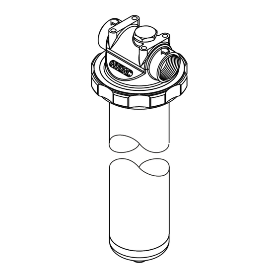
10. ANNEX 10.1.4 Spare parts MRF1-E 9007199323288459 The following spare parts are available for the filter housing: Fig. 9: Spare parts MRF1-E Item Designation Part no. Qty. Filter bowl 10“ 3204371 Filter bowl 20“ 3204372 Filter bowl 30“ 3204373 Filter bowl 40“... -
Page 45: Tab. 14 Spare Parts Mrf1-E
10. ANNEX Item Designation Part no. Qty. Bleed screw 545033 Profile seal ring 413429 Profile seal ring 411600 O-ring 610433 O-ring 604075 Filter element, see ▶Sec. 10.1.1 "Filter elements – Flexmicron Economy FM-E" or ▶Sec. 10.1.2 "Filter elements – Flexmicron Standard FM-S" or ▶Sec. 10.1.3 "Filter elements –... -
Page 46: Spare Parts Mrf1-N
10. ANNEX 10.1.5 Spare parts MRF1-N 9007199323300235 The following spare parts are available for the filter housing: Fig. 10: Spare parts MRF1-N Item Designation Part no. Qty. Filter bowl 10“ 3542319 Filter bowl 20“ 3542357 Filter bowl 30“ 3542358 Filter bowl 40“... -
Page 47: Tab. 15 Spare Parts Mrf1-N
10. ANNEX Item Designation Part no. Qty. Bleed screw 245045 Profile seal ring 413429 Profile seal ring 411600 O-ring 610433 O-ring 604075 Filter element Clogging indicator Tab. 15: Spare parts MRF1-N *) available on request 47 / 60 3550863e / 2024-08... -
Page 48: Contacting Customer Service
Contact details such as the telephone numbers, e-mail and mailing addresses for the Hotline, product support, Customer Service, branch offices, service partners for mainte- nance, repair and spare parts can be found on our homepage www.hydac.com. HYDAC SYSTEMS & SERVICES GMBH Friedrichsthaler Str. -
Page 49: Tab. 16: Differential Pressure Indicator, Visual Vm X B.x
10. ANNEX Display type Visual display with green-red field, auto- matic return Weight 55 g Response pressure or indication range VM 2 B.x = 2 bar -10% VM 3 B.x = 3 bar -10% VM 5 B.x = 5 bar -10% VM 8 B.x = 8 bar ±10% Permitted operating pressure ≤ 210 bar Permitted temperature range -30 … +100 °C Connector thread G ½ Required installation space According to HN 28-22 Maximum tightening torque... -
Page 50: Differential Pressure Indicator, Visual - Vm X Bm
10. ANNEX 10.3.2 Differential pressure indicator, visual – VM x BM.x 36028797208484619 The visual differential pressure indicator reacts to the increasing pressure difference as the contamination level of the filter element increases. Fig. 12: Differential pressure indicator, visual VM x BM.x Display type Visual display with green-red field, manual return Weight 55 g... -
Page 51: Differential Pressure Indicator, Electrical - Vm X C
10. ANNEX 10.3.3 Differential pressure indicator, electrical – VM x C.x 36028797208611723 The electrical differential pressure indicator reacts to the increasing pressure difference as the contamination level of the filter element increases. Fig. 13: Differential pressure indicator, electrical VM x C.x Display type Electrical switch Weight 120 g Response pressure or indication range... -
Page 52: Differential Pressure Indicator, Electrical - Vm X D.x /-L-Xx
10. ANNEX 10.3.4 Differential pressure indicator, electrical – VM x D.x /-L-xx 36028797208620427 The electrical differential pressure indicator reacts to the increasing pressure difference as the contamination level of the filter element increases. Fig. 14: Differential pressure indicator, electrical VM x D.x /-Lxx Display type Visual display and electrical switch Weight 150 g Response pressure or indication range... - Page 53 TABLE OF ILLUSTRATIONS Table of illustrations Fig. 1 Pressure loss curve ....................Fig. 2 Pressure loss formula, filter element ................ Fig. 3 Decoding the type label .................... Fig. 4 Model code ....................... Fig. 5 Components MRF1 E ....................Fig. 6 Components MRF1 N....................
-
Page 54: Index Of Tables
INDEX OF TABLES Index of tables Tab. 1 Target groups ......................Tab. 2 Depiction of the warning levels................. Tab. 3 Checking the scope of supply................... Tab. 4 Technical data – MRF1 E ..................Tab. 5 Technical data – MRF1 N / MRF1 K................. Tab. -
Page 55: Glossary
GLOSSARY Glossary Glass fibre HYDAC standard with dimensions for the installation space for HYDAC clogging indicators. Polyamide Polyester Polypropylene β-value (beta value) The β-value is a measure of the effec- tiveness of a filter element. For a specific particle size x, this β-value defines the... -
Page 56: Index
Economy 18 Warranty 2, 8 Premium 17 Standard 18 Fluid temperature range 14, 15 Hotline 48 Humidity 14, 15 HYDAC Branch offices 48 Germany 48 Product support 48 Service 48 Service partners 48 Terms of delivery 8 Operating pressure 14, 15 56 / 60... - Page 57 57 / 60 3550863e / 2024-08...
- Page 58 58 / 60 3550863e / 2024-08...
- Page 59 59 / 60 3550863e / 2024-08...
- Page 60 HYDAC Filter Systems GmbH Industriegebiet 66280 Sulzbach/Saar Germany Tel. +49 6897 509-01 filtersystems@hydac.com www.hydac.com Further addresses: www.hydac.com/en/contacts...
Need help?
Do you have a question about the MultiRheo MRF 1 E 1 Series and is the answer not in the manual?
Questions and answers