Chapters
Table of Contents

Related Manuals for Hydac MFU-30E


Summary of Contents for Hydac MFU-30E
- Page 1 MFU-30E MobileFiltration Unit Operating and Maintenance Instructions English (translation of original instructions) Document No. : 4073898a Follow these instructions for proper and safe use. Keep for future reference.
- Page 2 Executive directors: Mathias Dieter, Dipl.Kfm. Wolfgang Haering Documentation Representative The contact data of the person authorized with the documentation is: Günter Harge c/o HYDAC International GmbH, Industriegebiet, 66280 Sulzbach / Saar Germany Telephone: +49 6897 509 1511 Fax: +49 6897 509 1394 E-Mail: guenter.harge@hydac.com...
-
Page 3: Table Of Contents
Decoding the name plate ................ 23 3.4.1 Model Code.................. 25 Technical data .................... 26 Dimensions and Hydraulic shematic ............ 29 3.6.1 MFU-30E9-... Economy .............. 29 3.6.1.1 Dimensions / hydraulic diagram.......... 30 Design and function.................. 33 3.7.1 Function ................... 35 Transportation / Storage .................. 37 BeWa MFU-30E 4073898a en-us web... - Page 4 Rectifying malfunctions .................. 60 Performing Maintenance .................. 63 Maintenance table .................. 64 Changing the filter element ................ 65 Removing/installing the protective screen ............ 70 Checking/cleaning the protective screen............ 72 Decommissioning / Disposal .................. 74 Temporary shutdown.................. 74 Final Decommissioning ................ 74 Disposal/Recycling .................. 74 BeWa MFU-30E 4073898a en-us web...
- Page 5 HYDAC FILTER SYSTEMS GMBH Table of Contents Appendix ........................ 75 EC declaration of conformity ................ 75 Contacting Customer Service............... 75 Finding spare parts/accessories.............. 76 A.3.1 Finding the filter elements.............. 77 A.3.2 Accessories list ................ 78 Glossary ......................... 82 Index ........................ 85 BeWa MFU-30E 4073898a en-us web...
-
Page 6: General
Additionally, please observe the product- related instructions and requirements. Operator, specialist Read, observe and follow this manual and personnel: the associated documents, in particular, the safety and warning instructions. Tab. 1: Target group 6 / 88 BeWa MFU-30E 4073898a en-us web... -
Page 7: Illustrations In The Manual
Fig. 1: Overview / labeling of the title page Short name of the product / product name Type of document Language Document no. / Index Supplementary instructions regarding the validity of the manual (optional) BeWa MFU-30E 4073898a en-us web 7 / 88... -
Page 8: Representation Of Requirements
(1., 2., 3., etc.). An example for procedural instructions with a fixed sequence: 1. Remove the transport securing device. 2. First fill the product. 3. Switch the product on. 8 / 88 BeWa MFU-30E 4073898a en-us web... -
Page 9: Representation Of Intermediate Results/Results
An example for a procedural instruction with intermediate re- sult and final result: 1. Switch the product on. ð The display lights up. 2. Press the button. O The product is now ready for use. BeWa MFU-30E 4073898a en-us web 9 / 88... -
Page 10: Supplementary Symbols
Warning/General Safety Information, which is placed ahead of each activity, are represented as follows: CAUTION Type and source of danger Consequence of the danger Hazard symbol Measures to avert danger ► 10 / 88 BeWa MFU-30E 4073898a en-us web... -
Page 11: Signal Words And Their Meaning In The General Safety Information
ENVIRONMENTALLY TIP ENVIRONMENTALLY TIP – The signal word indicates a haz- ardous situation without a high level of risk, which, if not avoided, will result in environmental contamination. BeWa MFU-30E 4073898a en-us web 11 / 88... -
Page 12: Exclusion Of Liability/Warranty
Any infringements to the above shall be liable to damage compensation. 12 / 88 BeWa MFU-30E 4073898a en-us web... -
Page 13: Safety
– *To clearly lay down and define the responsibilities for the installation, operation, troubleshooting, maintenance and cleaning – To ensure that all the employees have read and under- stood the instructions BeWa MFU-30E 4073898a en-us web 13 / 88... - Page 14 Knowledge about handling the test liq- uid is required Troubleshooting Specialist personnel Safe handling/use Maintenance De- - Mechanical of tools. commissioning, Dis- Specialist personnel Product-specific assembly - Electrical knowledge is re- quired. 14 / 88 BeWa MFU-30E 4073898a en-us web...
-
Page 15: Tab. 2 Target Group / Required Personnel Qualification
Service personnel / sioning, Operation, - Service / Adminis- Administrator / HY- Troubleshooting trator DAC Service. Maintenance Dis- Extensive experi- posal ence of the product. Tab. 2: Target group / Required personnel qualification BeWa MFU-30E 4073898a en-us web 15 / 88... -
Page 16: Safety Marking
Decoding the name plate [} 23] 2 Label Dangerous electrical voltage warning 3 Label Rotational direction arrow pointing to the electric motor 4 Embossed sign Characteristics of the electric motor 16 / 88 BeWa MFU-30E 4073898a en-us web... -
Page 17: Observing Regulatory Information
Switch off the product at the main switch. 2.6 Fire-fighting / Extinguishing a fire Use a powder extinguisher that corresponds to fire class B as per EN 2 to extinguish any fires / to fight fires. BeWa MFU-30E 4073898a en-us web 17 / 88... -
Page 18: Fig. 3 Fire Protection Class B
Maintain a minimum safe distance from electrical components. For a mains voltage of up to 1000 V, the minimum safe dis- tance is 1 m. Fig. 3: Fire protection class B Fig. 4: Minimum distance for fire fighting 18 / 88 BeWa MFU-30E 4073898a en-us web... -
Page 19: Performance And Product Description
– Increased oil service life – Higher machine availability – Simple operation – Compact design – Small, mobile filter unit – Removal of small quantities of free water in oil is possible BeWa MFU-30E 4073898a en-us web 19 / 88... -
Page 20: Proper/Designated Use
The manufacturer assumes no responsibility for determining the interfaces for installation in a system or the installation, use or functionality of the product in this system. 20 / 88 BeWa MFU-30E 4073898a en-us web... -
Page 21: Improper Use Or Use Deviating From Intended Use
NOTICE Impermissible operating media The filter unit will be damaged. u Never pump: - water - corrosive fluids - acids or solvents - oily sludge or sediment in the oil tank BeWa MFU-30E 4073898a en-us web 21 / 88... -
Page 22: Checking The Scope Of Delivery
Qty. Description Filter unit MFU (version depending on the order) Sliding grip Technical documentation, consisting of: – Operating and Maintenance Instructions (this document) – CE declaration of conformity Tab. 3: Scope of delivery 22 / 88 BeWa MFU-30E 4073898a en-us web... -
Page 23: Decoding The Name Plate
3.4 Decoding the name plate Identification details of the filter unit can be found on the name plates on the filter unit and the components. Always mention the part no. and the serial no. when contacting HYDAC. Fig. 5: Decoding the name plate Item Description... - Page 24 3 | Performance and product description HYDAC FILTER SYSTEMS GMBH P Inlet pressure IN H Suction height Flow rate Flow rate Viscosity range Viscosity range Temp. oil Permissible fluid temperature range Temp. amb. Permissible ambient temperature range Weight Empty weight 24 / 88 BeWa MFU-30E 4073898a en-us web...
-
Page 25: Model Code
X = Other voltage on request Sealing material F = FKM (FPM, Viton®) Clogging indicator BF = Differential pressure indicator, visual Supplementary details * = With cCSAus approval and NEMA 5-15 plug Fig. 6: Model Code BeWa MFU-30E 4073898a en-us web 25 / 88... -
Page 26: Technical Data
Response pressure of the 6 bar pressure relief valve Response pressure of the 3 bar clogging indicator Inlet pressure IN -0.4 … 0.5 bar Suction height ≤ 2 m Hydraulic connections – IN 35L (M45x2, according to ISO8434-1) 26 / 88 BeWa MFU-30E 4073898a en-us web... - Page 27 If the service and maintenance intervals are followed, the in- tended service life of the unit is not limited. @ 250 mm²/s when using original HYDAC accessories. At an installation height ≤ 1000 m above sea level. BeWa MFU-30E 4073898a en-us web 27 / 88...
-
Page 28: Tab. 4 Technical Data
3 | Performance and product description HYDAC FILTER SYSTEMS GMBH The IP protection class of the installed power plug can devi- ate from this. See IEC DIN EN 60204-1, Chapter 7.2.2. Tab. 4: Technical data 28 / 88 BeWa MFU-30E 4073898a en-us web... -
Page 29: Dimensions And Hydraulic Shematic
Check the model code on the name plate of the filter unit. 3.6.1 MFU-30E9-... Economy The drawings/dimensions of the filter unit can be found below. AC electric motor DC electric motor BeWa MFU-30E 4073898a en-us web 29 / 88... -
Page 30: Dimensions / Hydraulic Diagram
3 | Performance and product description HYDAC FILTER SYSTEMS GMBH 3.6.1.1 Dimensions / hydraulic diagram The filtration unit has the following dimensions: Fig. 7: Dimensions with AC electric motor All dimensions in mm. 30 / 88 BeWa MFU-30E 4073898a en-us web... -
Page 31: Fig. 8 Dimensions With Dc Electric Motor
HYDAC FILTER SYSTEMS GMBH Performance and product description | 3 Fig. 8: Dimensions with DC electric motor All dimensions in mm. BeWa MFU-30E 4073898a en-us web 31 / 88... -
Page 32: Fig. 9 Hydraulic Diagram
The filter unit has the following hydraulic diagram: Fig. 9: Hydraulic diagram IN Inlet OUT Outlet 115 Vane pump 133 Clogging indicator, differential pressure indicator 310 Electric motor 710 Protective screen 900 Filter element 32 / 88 BeWa MFU-30E 4073898a en-us web... -
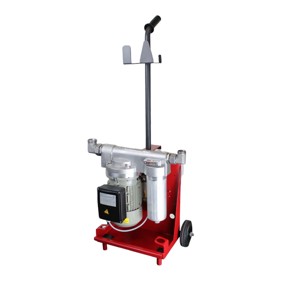
Page 33: Design And Function
HYDAC FILTER SYSTEMS GMBH Performance and product description | 3 3.7 Design and function The following components/operating elements can be found on the filter unit: Fig. 10: Components / Operating parts IN Inlet OUT Outlet BeWa MFU-30E 4073898a en-us web 33 / 88... - Page 34 160 Hose retainer 165 Cable holder 310 Electric motor 330 Terminal box with main switch 331 Connector cable with power plug 600 Filter bowl 710 Protective screen 900 Filter element 910 Empty element 34 / 88 BeWa MFU-30E 4073898a en-us web...
-
Page 35: Function
The filter unit has a motor-pump assembly (310) for which the vane pump is integrated directly in the connector head (110). The drive motor (310) is, depending on the version, an electric motor with alternating current. BeWa MFU-30E 4073898a en-us web 35 / 88... - Page 36 (150). – Filter bowl (600) for the filter element (not included in the scope of delivery). – A differential pressure indicator (133) for displaying the contamination level of the filter element. 36 / 88 BeWa MFU-30E 4073898a en-us web...
-
Page 37: Transportation / Storage
NOTICE! Hold the filter unit only at the push handle and the front grip strip to transport it. Fig. 12: Transporting the filtration unit Transport the filter unit only with the push handle and while rolling it along its own axis. BeWa MFU-30E 4073898a en-us web 37 / 88... -
Page 38: Storing The Filter Unit (>6 Months)
You will find the respective information on the prevention of damage to the filter unit during storage (>6 months) in this chapter. Remove and dispose of the used filter element and clean the inside of the filter bowl. 38 / 88 BeWa MFU-30E 4073898a en-us web... -
Page 39: Transporting/Storing The Filter Unit With Hoses And Lances
Insert both the lances into the holders for that purpose on the filter unit from the top. Fig. 13: Transporting/storing the filter unit BeWa MFU-30E 4073898a en-us web 39 / 88... -
Page 40: Setting Up / Assembly / Integration Of The Filter Unit
3. Secure the clip pin (112) by turning over the spring clip. O The mounting of the push handle is complete. Dismount the push handle by opening and pulling the clip pin. 40 / 88 BeWa MFU-30E 4073898a en-us web... -
Page 41: Avoiding Siphoning
After the filter unit is switched off, the height difference or pri- mary pressure can cause the flow to occur both in and against the feed direction and the fluid can leak uncontrollably. BeWa MFU-30E 4073898a en-us web 41 / 88... -
Page 42: Avoiding The Mixing Of Oils - Emptying The Filter Unit
– Modified response to water – More deposits due to additive reactions – More system contamination due to detached deposits – Changed water/air absorption and air release behavior – Greater tendency to foam 42 / 88 BeWa MFU-30E 4073898a en-us web... -
Page 43: Making The Electrical Connections
Depending on the version, the filter unit has a motor protec- tion switch in the terminal box along with a main switch to pro- tect it from electrical overload. BeWa MFU-30E 4073898a en-us web 43 / 88... -
Page 44: Connecting The Filter Unit With 24 V Dc
O The filter unit is electrically connected. Disconnecting To disconnect the battery clamps, proceed as follows: 8. Switch the filter unit off at the main switch 9. First release the black battery clamp. 44 / 88 BeWa MFU-30E 4073898a en-us web... - Page 45 HYDAC FILTER SYSTEMS GMBH Setting up / assembly / integration of the filter unit | 5 10. Then release the red battery clamp. O The disconnection of the battery clamps is complete. BeWa MFU-30E 4073898a en-us web 45 / 88...
- Page 46 5. Switch the filter unit on at the main switch. ð The motor pump group begins to pump. 6. Switch the filter unit off at the main switch. O The filter unit is electrically connected. 46 / 88 BeWa MFU-30E 4073898a en-us web...
-
Page 47: Connecting The Suction/Pressure Port
– Use a suction hose that is suitable for a vacuum of ≥ -0.5 bar (e.g. -1 bar). – Avoid constrictions in the connected hoses. This reduces the power and increases the risk of cavitation. BeWa MFU-30E 4073898a en-us web 47 / 88... - Page 48 – Ensure that the connecting lines (suction side / pressure side) do not transfer any voltage or cause vibrations on the unit. Use hoses or compensators if necessary. 48 / 88 BeWa MFU-30E 4073898a en-us web...
-
Page 49: Attaching/Connecting The Suction/Pressure Hoses (Accessories)
Secure the hose so that it cannot fall out or float. Check that no shut-off devices in the lines/hoses are ob- structed. Make sure there is a depressurized outlet. BeWa MFU-30E 4073898a en-us web 49 / 88... -
Page 50: Commissioning The Filter Unit
5 minutes of opera- tion, switch the filter unit off. Fill the motor-pump group with fluid through the suction hose and switch the filter unit on once again. O The commissioning is complete. 50 / 88 BeWa MFU-30E 4073898a en-us web... - Page 51 Empty the contents of the suction and pressure hoses into the respective containers and secure the cable and hoses as described in Chapter Transportation / Storage [} 37]. BeWa MFU-30E 4073898a en-us web 51 / 88...
-
Page 52: Manual Operation
Fig. 17: Main switch on terminal box with DC electric motor After switching the unit off at the main switch, depressurized oil can escape at the ports depending on the conditions or in- stallation. 52 / 88 BeWa MFU-30E 4073898a en-us web... -
Page 53: Observe The Optical Clogging Indicator
Check this clogging indicator daily during operation. Replace the filter element when there is a differential pressure of 3 bar Fig. 18: Visual clogging or as soon as the clogging indicator enters the red zone. indicator BeWa MFU-30E 4073898a en-us web 53 / 88... -
Page 54: Selecting The Operating Modes
- The pressure hose allows the cleaned oil to flow back into the reservoir, as far as possible at the top of the reservoir, but below the oil level, without the oil being enriched with air. 54 / 88 BeWa MFU-30E 4073898a en-us web... -
Page 55: Recirculation With Filtration/Dewatering
3. Connect the filter unit to the voltage source. 4. Switch the filter unit on at the main switch. BeWa MFU-30E 4073898a en-us web 55 / 88... - Page 56 O Recirculation with filtration/dewatering is complete. NOTICE Transport/storage after operation with dewatering The filtration unit will be damaged by corrosion u Pump/flush the filter unit fully with oil after operation with dewatering. 56 / 88 BeWa MFU-30E 4073898a en-us web...
-
Page 57: Circulation Pumping Without Filtration
3. Connect the filter unit to the voltage source. 4. Switch the filter unit on at the main switch. BeWa MFU-30E 4073898a en-us web 57 / 88... - Page 58 8. Empty the contents of the suction hose into the oil tank/ container. 9. Secure the cable and, if required, the hoses to the filter unit, see Transportation / Storage [} 37]. O Recirculation is complete. 58 / 88 BeWa MFU-30E 4073898a en-us web...
-
Page 59: Operation With Accessories
Screw the suction line filter on the suction hose, e.g. instead of the lance and hang this into the container to be cleaned. During operation with the suction line filter on the suction hose please note the permissible viscosity is ≤ 200 mm²/s. BeWa MFU-30E 4073898a en-us web 59 / 88... -
Page 60: Rectifying Malfunctions
Replace it closed. if necessary. There is air in Fill the vane the suction line pump through and the vane the suction hose/ pump. quick coupling. 60 / 88 BeWa MFU-30E 4073898a en-us web... - Page 61 The viscosity of Check the vis- the fluid is too cosity of the high. fluid. Heat the fluid to achieve the per- missible viscos- ity. BeWa MFU-30E 4073898a en-us web 61 / 88...
-
Page 62: Tab. 5 Error/Cause/Rectification
The running The protective Clean the pro- noise of the mo- screen is tective screen. tor-pump assem- clogged. bly becomes substantially louder. Tab. 5: Error/cause/rectification 62 / 88 BeWa MFU-30E 4073898a en-us web... -
Page 63: Performing Maintenance
Danger of bodily injury u The hydraulic system must be depressurized before per- forming any work on it. Depending on the model of the filter unit, the changing of the filter element is different, too. BeWa MFU-30E 4073898a en-us web 63 / 88... -
Page 64: Maintenance Table
Removing/in- stalling the pro- tective screen Checking/clean- ing the protective screen Changing the fil- ter element Checking/clean- ing the protective screen 1 - Operating personnel; 2 - Specialist personnel – Mechanical 64 / 88 BeWa MFU-30E 4073898a en-us web... -
Page 65: Changing The Filter Element
The filter element / empty element has two seal rings (901) + (902) installed. Before assembly, check for damage and also for the correct placement of the seal rings (901)+(902). BeWa MFU-30E 4073898a en-us web 65 / 88... - Page 66 3. Remove the pressure hose from the container. 4. Switch off the filter unit at the main switch and unplug the power connector. 66 / 88 BeWa MFU-30E 4073898a en-us web...
- Page 67 9. Clean the sealing surface on the connector head and the filter bowl. Also clean the inside of the filter bowl. BeWa MFU-30E 4073898a en-us web 67 / 88...
- Page 68 NOTICE! Damaged O-rings cause leakage in the filter bowl. 13. Insert the filter bowl along with the filter element from below to the connector head. 68 / 88 BeWa MFU-30E 4073898a en-us web...
- Page 69 = 24 mm to ≈ 40 Nm. 15. Switch on the filter unit and check for any leaks. O The replacement of the filter element is now complete. BeWa MFU-30E 4073898a en-us web 69 / 88...
-
Page 70: Removing/Installing The Protective Screen
The filter unit will be damaged/destroyed u Always operate the filter unit with a protective screen. 1x wrench = 50 mm 1x long-nosed pliers Fig. 22: Removing/installing the protective screen For removal, proceed as follows: 70 / 88 BeWa MFU-30E 4073898a en-us web... - Page 71 = 50 6. If necessary, mount the suction hose on the inlet con- nector (700). O The assembly of the protective screen is complete. BeWa MFU-30E 4073898a en-us web 71 / 88...
-
Page 72: Checking/Cleaning The Protective Screen
3. Check the protective screen for damage. NOTICE! If the web of the protective screen is dam- aged, replace it immediately. ð The cleaning of the strainer is complete. 72 / 88 BeWa MFU-30E 4073898a en-us web... - Page 73 HYDAC FILTER SYSTEMS GMBH Performing Maintenance | 8 4. Assemble the protective screen according to Chapter Removing/installing the protective screen [} 70]. O The assembly of the protective screen is complete BeWa MFU-30E 4073898a en-us web 73 / 88...
-
Page 74: Decommissioning / Disposal
Dispose of the dismounted individual parts/drained operating fluids/fluids in an environmentally friendly manner. Follow the respective national regulations. 74 / 88 BeWa MFU-30E 4073898a en-us web... -
Page 75: Ec Declaration Of Conformity
HYDAC SYSTEMS & SERVICES GMBH Friedrichsthaler Str. 15, Werk 13 66450 Neunkirchen - Heinitz Germany Telephone: +49 6897 509 01 Fax: +49 6897 509 324 E-mail: service@hydac.com Homepage: www.hydac.com Tab. 7: HYDAC Service Deutschland BeWa MFU-30E 4073898a en-us web 75 / 88... -
Page 76: Finding Spare Parts/Accessories
The following spare parts are available for your selection: Item Description Part no. Filter bowl 4171296 Protective screen 4331774 Filter element, see Finding the filter elements [} 77] Empty element, see Finding the filter elements [} 77] Tab. 8: Spare parts list 76 / 88 BeWa MFU-30E 4073898a en-us web... -
Page 77: Finding The Filter Elements
Empty element NX9xxxxx-F 4265963 Tab. 11: Empty element for circulation pumping To check online availability of replacement filter elements and/ or place an order, scan the QR code or select the link: https://spare-elements.hydac.com/ BeWa MFU-30E 4073898a en-us web 77 / 88... -
Page 78: Accessories List
Suction hose with lance, length = 2.5 m 1SN / 2TE 4510245 Pressure hose with lance, length = 2.5 m Thread: M45x2 / M36x2 ISO8434-1-28L ISO8434-1-28L M36x2 M36x2 ISO8434-1-35L ISO8434-1-35L M45x2 M45x2 78 / 88 BeWa MFU-30E 4073898a en-us web... - Page 79 Pressure hose with lance, length = 5 m Thread: M45x2 / M36x2 ISO8434-1-28L ISO8434-1-28L M36x2 M36x2 ISO8434-1-35L ISO8434-1-35L M45x2 M45x2 Suction line filter M45x2 4510248 (for installation on the suction hose only for viscosity <200 mm²/s) Tab. 12: Accessories list BeWa MFU-30E 4073898a en-us web 79 / 88...
- Page 80 Visual clogging indicator................Fig. 18 Example of application: Recirculation with filtration/dewatering ....Fig. 19 Empty element ..................Fig. 20 Example of application: Recirculation ............Fig. 21 Removing/installing the protective screen ..........Fig. 22 80 / 88 BeWa MFU-30E 4073898a en-us web...
- Page 81 Spare parts list ..................Tab. 9 Filter elements for filtering ................ Tab. 10 Filter elements for filtering and dewatering ..........Tab. 11 Empty element for circulation pumping ............ Tab. 12 Accessories list..................BeWa MFU-30E 4073898a en-us web 81 / 88...
-
Page 82: Glossary
The above 200 bar and meet the normal reaction is irreversible, that means thermal loads. HLP according to DIN 51524, Part 2: with active sub- stances for increasing corrosion 82 / 88 BeWa MFU-30E 4073898a en-us web... - Page 83 The equipment, sources and also based on mineral which is covered by this part of IEC oil. They are highly biologically BeWa MFU-30E 4073898a en-us web 83 / 88...
- Page 84 HV: with active substances for in- creasing corrosion protection, resis- tance to aging, reduction of wear due to scoring in mixed friction ar- eas and improvement in the viscos- ity-temperature behavior. 84 / 88 BeWa MFU-30E 4073898a en-us web...
-
Page 85: Index
42 Disposal 74 recycle 74 operating mode recirculation with filtration 55 exclusion of liability 12 recirculation with filtration/dewater- 55 recirculation without filtration 57 filter element select 54 Operation 51 BeWa MFU-30E 4073898a en-us web 85 / 88... - Page 86 Terms of Delivery 12 suction line filter on the suction hose the filter element permissible viscosity 59 replacing 66 suction line filter on the suction hose. 59 Support 75 use: technical data 26 86 / 88 BeWa MFU-30E 4073898a en-us web...
- Page 87 HYDAC FILTER SYSTEMS GMBH Index Intended 20 visual check 51 warranty 12 BeWa MFU-30E 4073898a en-us web 87 / 88...
- Page 88 www.hydac.com...
Need help?
Do you have a question about the MFU-30E and is the answer not in the manual?
Questions and answers