
Related Manuals for Atlas Copco HiLight V4


Summary of Contents for Atlas Copco HiLight V4
- Page 1 Instruction Manual Instruction Manual For Portable Light Tower Generators English HiLight V4 Engine Kubota Z482 HiLight V5+...
- Page 3 Instruction Manual For Portable Light Tower Generators HiLight V4 HiLight V5+ Original instructions Printed matter No. 9829 3827 02 ATLAS COPCO - PORTABLE ENERGY DIVISION www.atlascopco.com 04/2022...
- Page 4 Neglecting maintenance or making changes to the setup of the machine can result in major hazards, including fire risk. While every effort has been made to ensure that the information in this manual is correct, Atlas Copco does not assume responsibility for possible errors.
-
Page 5: Table Of Contents
Preface Deployment..........23 5.4.1 Levelling the trailer........23 Please read the following instructions carefully Main parts - HiLight V4 ......7 before starting to use your light tower. 5.4.2 Raising the tower ........23 5.4.3 Lowering the tower ........25 It is a solid, safe and reliable machine, built Main parts - HiLight V5+...... - Page 6 Disposal of materials........88 Maintenance..........71 16.3 Directive 2012/19/EU of the European 12.1 Maintenance schedule of HiLight V4 ..71 parliament and of the council on waste 12.2 Maintenance schedule for HiLight V5+..74 electrical and electronic equipment (WEEE) ..............88 Technical specifications ......
-
Page 7: Main Parts - Hilight V4
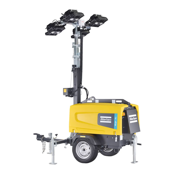
Main parts - HiLight V4 “The light tower provides an undercarriage (frame, axle and towbar) and 4 floodlights of 1000 W each or 4 LED floodlights of 350 W each. The light tower is very useful for construction sites where no electricity nor lighting is available.”... -
Page 8: Main Parts - Hilight V5
Main parts - HiLight V5+ - 8 -... -
Page 9: Safety Information
Do not position light tower unit and contact Atlas Copco. CAUTION under power lines. Crush hazard. - Ensure the trailer is well grounded, per all Ensure the light tower is in good operating condition: applicable regulations. -
Page 10: Engine Safety
Engine safety CAUTION DANGER Operator safety Risk of severe burn. Asphyxiation hazard. Before handling lights, allow - Operate the engine outdoors DANGER lights to cool for 15 minutes. and keep away from engine exhaust. Explosion hazard. - If operating in an enclosed - Keep engine, fuel, and other area, vent exhaust fumes to combustibles away from... -
Page 11: California Proposition 65
Service safety During servicing CAUTION Risk of severe burn. • Keep hands, feet, and loose clothing away from Before servicing moving parts on engine and generator. - Do not touch the engine, exhaust pipes, or areas near • Keep the light tower and all its components clean. the exhaust at rear of trailer. -
Page 12: Labels
Labels Labels provide instructions and information. They also warn of hazards. For convenience and safety, keep all labels in legible condition, replacing labels when damaged or missing. Replacement labels are available from the factory. Samples of labels and their descriptions are provided in section Label samples and descriptions. Label locations - 12 -... - Page 13 Label samples and descriptions Label Description Label Description 1092 6814 00 Decal: Electrical shock Decal: Tyre Pressure 1092 6819 00 Decal: Operation manual 1092 6805 00 Decal: Towing instruction - 13 -...
- Page 14 Label Description Label Description 1092 6829 00 Decal : High voltage Deacl : Flash 1092 6812 00 Decal : Light 1092 6813 00 Decal : Poison - 14 -...
- Page 15 Label Description Label Description 1094 2280 00 Decal : Danger electrical 1079 9919 51 Decal: Rotation direction power line Decal : Replace wire or winch 1092 6822 00 Decal : Fan - 15 -...
- Page 16 Label Description Label Description Fork lift Decal : Hot 1092 6806 00 Decal : Lifting hook 1092 6824 00 Decal : Grounding round - 16 -...
- Page 17 Label Description Label Description Decal : ATLAS COPCO black Decal : ATLAS COPCO white - 17 -...
-
Page 18: Assembly
Assembly Tow hitch Assemble loose parts before use Notice There are 3 options for tow hitch. Check and unload loose parts before unloading units - Pintle hook from container. - 2-inch-ball • A - Drawbar with towing hitch (option) - Combo hitch for a 2-inch-ball and pintle hook •... -
Page 19: Light Fixture Wiring
Light fixture wiring - 19 -... -
Page 20: Operation
Operation Safety b If necessary, attach a red flag to the end of the mast. Before operating the light tower, read and be familiar 2. Check tires, wheels, and lights: with this instruction manual. a Check tires for wear. Replace worn tires. Read and follow all safety instructions (see page 8). -
Page 21: During Towing
During towing Hoisting • Do not tow the trailer with any people, parts, The light tower may be hoisted by means of the hoist supplies, or additional equipment attached to it or ring or forklift slots mounted on the lifting beam. loaded onto it. -
Page 22: Location
Location Hoisting ring and forklift slots • To achieve the best possible light coverage, locate the light tower on the same level as the area to be lighted, or higher. • To reduce the risk of personal injury, ensure the surrounding area is in good order and free of debris. -
Page 23: Deployment
Deployment the locking pin snaps into position with an audible e Take the weather into account: do not raise or use “click.” the tower in high winds or an electrical storm. The tower can afford 80 km/h wind load. 7. Pull the jack locking pin and rotate the jack Levelling the trailer downward until the locking pin engages. - Page 24 2. To raise the tower and follow these instructions: a Remove the horizontal-lock pin from the transport cradle. b Rotate the handle of the drawbar-mounted winch to tighten the cable and raise the light tower mast. Raising the tower - 24 -...
-
Page 25: Lowering The Tower
Lowering the tower Before moving or storing the light tower, lower the mast and lock it in place. To lower the tower and use the following instructions. 1. Turn off the tower lights and the engine. For increased lamp life, allow the lights to cool for 15 minutes before proceeding. -
Page 26: Engine Operation
Engine operation Starting the engine 3. When the glow-plug indicator light goes out, turn and hold the key at the START position. 1. Before starting the engine: 4. Release the key as soon as the engine starts, or after a Observe all engine safety precautions in page 8. 10 seconds if the engine does not start. -
Page 27: Automatic Engine Shutdown
Stopping the engine • After the metal halide lamps are turned off, they Lamps that will not turn on will not turn on again until they are cool. The To stop the engine: If the lamps do not light when power is applied, lamps can take up to 15 minutes to cool. -
Page 28: Floodlight Lux Level - Hilight V5
Floodlight lux level - HiLight V5+ Lamps Rotation angle Inclination angle Case Angle Lamp 1 Lamp 2 Lamp 3 Lamp 4 Inclination Rotation Inclination Rotation 80-70 80-70 80-70 80-70 Inclination -180 Rotation Inclination Rotation - 28 -... - Page 29 Case 1 Case 2 60 m 50 m Average Lux: 23 Average Lux: 23 4000 m² 3600 m² - 29 -...
- Page 30 Case 3 Case 4 Average Lux: 20 Average Lux: 33 5000 m² 2500 m² Lux level: - 30 -...
-
Page 31: Maintenance
Maintenance Daily inspection Lamp replacement c Remove the screws securing the flange rings and remove the flange rings. When the light tower is in regular use, the following To replace a light bulb (lamp) and follow the d Remove the protective lamp cover with the gasket items should be checked daily: instructions below. -
Page 32: Wiring Diagrams
Wiring diagrams Lamp Positioning Transport mode DANGER • Horizontal position. High voltage. Contact with live electrical Tilting circuits will cause severe injury or death. • Release the safety screw. • Rotate the lamps as per your desired position. • Turn off power before servicing any component on the light tower. -
Page 33: Circuit Diagrams
Circuit diagrams 9829 3552 00-01 Applicable for HiLight V4, HiLight V5+, engine circuit - 33 -... - Page 34 9829 3552 00-02 Applicable for HiLight V4, engine control circuit Preheat Start B(30) BR(AC) R1(19) C(17) R2(50) Notes, 1, When emergency stop switch is applied, this wire shall be replaced by switch wire 2. For standard and CE cubicles, wires should comply with CE.
- Page 35 9829 3552 00-03 HiLight V4, HiLight V5+, - 35 -...
- Page 36 9829 3552 00-04 HiLight V4, - 36 -...
- Page 37 9829 3552 00-05/01 HiLight V4, HiLight V5+, AC - 37 -...
- Page 38 9829 3552 00-05/02 HiLight V4 - 38 -...
- Page 39 9829 3552 00-06/01 HiLight V4, HiLight V5+, - 39 -...
- Page 40 9829 3552 00-06/02 HiLight V4, - 40 -...
- Page 41 9829 3552 00-07 HiLight V4, HiLight V5+, - 41 -...
- Page 42 9829 3552 50-01 Applicable for HiLight V4, HiLight V5+, ECU engine circuit - 42 -...
- Page 43 9829 3552 50-02 Applicable for HiLight V4, HiLight V5+, ECU control circuit Preheat Start B(30) BR(AC) R1(19) C(17) R2(50) - 43 -...
- Page 44 9829 3552 50-03 Applicable for HiLight V4, HiLight V5+, ECU control circuit Speed Speed Speed Speed Sensor Sensor Sensor Select Warning Water temp. Sensor Signal +12V +BP 12V -BP 0V, power ground Solenoid- Solenoid+ IG-SW ST-SW signal Lamp -S10 -B11...
- Page 45 9829 3552 50-04 HiLight V4, HiLight V5+, - 45 -...
- Page 46 9829 3552 50-05 HiLight V5+, - 46 -...
- Page 47 9829 3552 50-06 HiLight V4, HiLight V5+, - 47 -...
- Page 48 9829 3552 50-07 HiLight V5+, - 48 -...
- Page 49 9829 3581 00-01 HiLight V4, - 49 -...
- Page 50 9829 3581 00-02 HiLight V5+, Applicable for engine circuit Notes, 1. For standard and CE cubicles, wires should be comply with CE 2. Other circuit refer to 9829355250 except 9829355250-02 - 50 -...
- Page 51 9829 3552 60-01 Applicable for control circuit HiLight V4, Preheat Start B(30) BR(AC) R1(19) C(17) R2(50) Notes, 1, When emergency stop switch is applied, this wire shall be replaced by switch wire 2. Engine control circuit refer to 9829355200-01. 3. All wires comply with CSA.
- Page 52 9829 3552 60-02 Applicable for HiLight V4, AC power circuit 120/240V 60Hz Notes, 1. Only for controller cubicle LC1003 MKII 2. All wires comply with CSA. - 52 -...
- Page 53 9829 3552 60-03 Applicable for HiLight V4, lamp circuit 120/240V 60Hz With Longxin coil cord, wire color 51 and 53 are black; 56 and 58 are red; 52,54,57 and 59 are white; 55 is green/yellow; or with Philatron coil cord, wire color 51 is red; 53 is black; 56 is brown; 58 is orange; 52 is blue; 54 is yellow; 57 is purple; 59 is white; 55 is green.
- Page 54 9829 3552 65-01 Applicable for ECU control circuit HiLight V5+, Preheat Start B(30) BR(AC) R1(19) C(17) R2(50) Notes, 1. When emergency stop switch is applied, this wire shall be replaced by switch wire 2. Control circuit see page 9829355250-01,9829355250-03 3. All wires comply with CSA - 54 -...
- Page 55 9829 3552 65-02 Applicable for ECU control circuit HiLight V5+, Preheat Start B(30) BR(AC) R1(19) C(17) R2(50) Notes, 1. When emergency stop switch is applied, this wire shall be replaced by switch wire 2. Control circuit see page 9829355250-01,9829355250-03 3. All wires comply with CSA - 55 -...
- Page 56 9829 3552 65-03 Applicable for HiLight V5+, LED circuit 120V 60Hz only With Longxin coil cord, wire color 51 and 53 are black; 56 and 58 are red; 52,54,57 and 59 are white; 55 is green/yellow; or with Philatron coil cord, wire color 51 is red; 53 is black; 56 is brown; 58 is orange; 52 is blue; 54 is yellow; 57 is purple; 59 is white; 55 is green. Line White Load...
-
Page 57: Wiring Diagrams
Wiring diagrams Electrical system - 57 -... - Page 58 - 58 -...
-
Page 59: Schematic Diagrams
Schematic diagrams 9829 3552 51_SHT 01 - 59 -... - Page 60 9829 3552 51_SHT 02 - 60 -...
- Page 61 9829 3552 51_SHT 03 - 61 -...
-
Page 62: Axle Maintenance Manual
Axle maintenance manual Axle - 62 -... -
Page 63: Safety Precautions
Wheel bolt tightening torque Safety precautions • Tighten shaft nut, then back to loose 1/2 turn (180 °), then tighten 1/4 turn (90 °). • Not allowed on the shaft tube welding or drilling. • Check the wheel functioning - is free to rotate, and Thread Hexagon Tightening torque... -
Page 64: Setting The Lc1003™ Controller
Setting the Lc1003™ controller DOWN: Is used for navigating the Controller settings should only be instrumentation, event log and performed by a qualified technician. STOP: Is used to activate Stop/Reset configuration screens and to go to the mode. When pressing the STOP next parameter level. -
Page 65: Module Display
Module display Icon overview Display Description Instrumentation icons Appears when the event log is Home page being displayed Display Description The home page is the page displayed when no other The default home page which Current time held in the unit page has been selected: displays Generator voltage and the Auto Run icon... -
Page 66: Mode Icons
Front panel editor (FPE) / Auto Run icons Navigation menu Display Description To enter the navigation menu, press both the UP and Appears when the unit is in the Display Description DOWN buttons simultaneously. front panel editor. To navigate to the desired page, select the Appears when a remote start input corresponding icon by pressing the UP and DOWN is active... -
Page 67: Event Log
To view the event log: Display Description 1. Press the UP and DOWN buttons simultaneously Event Log to display the navigation menu. 2. Once entered, cycle to the event log section (1) and enter. Event log 3. To view the event log, repeatedly press the UP or The Lc1003™... - Page 68 Menu flow Configuration Parameters – Scheduler Enable Scheduler On (1), Off (0) Schedule Run On or Off On (1), Load Off (0) Schedule Period Weekly (0), Monthly (1) Scheduler (1) 0:00:00 Start Time Scheduler (1) Start Day (1=Monday) Scheduler (1) 1,2,3,4 Start Week Scheduler (1) Duration...
- Page 69 Setting the Lc1003™ clock Setting the Lc1003™ timer 907 Scheduler duration Set the desired time period. When this value is set, 1. Enter the weekly timer menu by pressing the 1. Enter the weekly timer menu as described above. Event 1 is closed. STOP and AUTO button simultaneously.
- Page 70 Setting the sensitivity regulator There are 2 blinking levels: The photocell sensitivity regulator is used for – Level 1: slow blinking ASM (Auto Rise and Lower Safety Mast) regulating the luminosity sensitivity level of the The photocell detects there is enough light, The ASM option provides the possibility to not only switch on/off the floodlights automatically, but also photocell.
-
Page 71: Maintenance
3002 6076 30 for the most important sub-assemblies, Atlas Copco has developed service kits that combine all wear parts. These service kits offer you the benefits of genuine parts, save on administration costs and are offered at reduces price, compared to the loose components. Refer to the parts list for more information on the contents of the service kit. - Page 72 Check rubber flexibles Check emergency stop Clean radiator Replace air filter element Check/Replace safety cartridge Inspection by Atlas Copco service technician Inspect starter motor Inspect waterpump Inspect alternator Check engine protective devices Check valve in the fuel return line (for mechanical injection system)
- Page 73 Check torque of wheel nuts Notes : (1) More frequently when operating in a dusty environment. (2) HiLight V4 add 2L oil, HiLight V5+ add 2.5L oil. (3) After a days work. (4) Change coolant every 2 years, coolant volume is 4L.
-
Page 74: Maintenance Schedule For Hilight V5
3002 6095 30 For the most important sub-assemblies, Atlas Copco has developed service kits that combine all wear parts. These service kits offer you the benefits of genuine parts, save on administration costs and are offered at reduces price, compared to the loose components. Refer to the parts list for more information on the contents of the service kit. - Page 75 Check rubber flexibles Check emergency stop Clean radiator Replace air filter element Check/Replace safety cartridge Inspection by Atlas Copco service technician Inspect starter motor Inspect waterpump Inspect alternator Check engine protective devices Check valve in the fuel return line (for mechanical injection system)
- Page 76 Check torque of wheel nuts Notes : (1) More frequently when operating in a dusty environment. (2) HiLight V4 add 2L oil, HiLight V5+ add 2.5L oil. (3) After a days work. (4) Change coolant every 2 years, coolant volume is 4L.
- Page 77 COIL CORD 1092872301 LAMP 1000W MH 1092629700 KEY SWITCH 1092684400 BULB LIGHT TOWER 1000W 1310072643 1094190004 COIL CORD 1092872301 HOUR METER 1092049817 KEY SWITCH 1092684400 BATTERY HILIGHT V5+ 1092852000 1094190004 HOUR METER 1092049817 BATTERY HILIGHT V4 1092852000 - 77 -...
-
Page 78: Technical Specifications
Technical specifications Reference conditions 1) 4) HiLight V4 50Hz HiLight V4 60Hz HiLight V5+ 50Hz HiLight V5+ 60Hz 1.Rated frequency 2.Rated speed 3000 3600 1500 1800 3.Generator service duty 4.Absolute inlet pressure 5.Relative air humidity 6.Air inlet temperature °C Limitations 2) 1.Maximum ambient temperature... - Page 79 HiLight V4 50Hz HiLight V4 60Hz HiLight V5+ 50Hz HiLight V5+ 60Hz Fuel consumption at 1 lamp on kg/h 1.23 1.52 0.45 0.56 Fuel consumption at 2 lamps on kg/h 1.40 1.68 0.52 0.59 Fuel consumption at 3 lamps on kg/h 1.59...
- Page 80 Design data 4) HiLight V4 50Hz HiLight V4 60Hz HiLight V5+ 50Hz HiLight V5+ 60Hz Alternator EN50081-1 EN50081-1 EN50081-1 EN50081-1 1.Standard EN50082-1 EN50082-1 EN50082-1 EN50082-1 2.Make Sincro Sincro Mecc Alte Mecc Alte 3.Model EK 2 MCT EK 2 MCT LT3N-75 LT3N-75 4.Rated output,class H temp.
-
Page 81: Circuit Breaker
HiLight V4 50Hz HiLight V4 60Hz HiLight V5+ 50Hz HiLight V5+ 60Hz 10.Speed governing mechanical mechanical mechanical mechanical 11.Capacity of oil sump 12.Electrical system Power circuit Circuit-breaker 1.Number of poles 2.Thermal release 31.25 31.25 12.5 12.5 (b) (c) 3.Magnetic release 1.25xIn... - Page 82 Notes 1) Reference conditions for engine performance to ISO 3046-1 / GB/T 6072.1 2) See derating diagram or consult the factory for other conditions 3) At reference conditions unless otherwise stated 4) Rating Definition (ISO 8528-1 / GB/T 2820.1): Limited Time Power is the maximum electrical power which a generating set is capable of delivering (at variable load), in the event of a utility power failure (for up to 500 hours per year of which a maximum of 300 hours is continuous running).
- Page 83 DERATING FACTOR LIGHT TOWER (%) 50 Hz 60 Hz LED 50/60 Hz For use of light tower outside these conditions, please contact Atlas Copco - 83 -...
-
Page 84: Options
Options Spark arresters Tow hitch Towing hitch combo IMPORTANT There are 3 options for tow hitch. State and local safety codes specify that, in certain - Pintle hook locations, internal combustion engines that use - 2-inch-ball hydrocarbon fuels must be used with spark arrestors. - Combo hitch for a 2-inch-ball and pintle hook A spark arresters is a device constructed of non- For cambo hitch option only:... -
Page 85: Towing Hitch Ring 2.5 Inch
Towing hitch ring 2.5 inch Cubicle ELCB with universal Road light system socket 230V 50Hz Cubicle ELCB without socket 230V 50Hz Control panels E-Stop The light tower control panel comprises: • Circuit breakers for engaging power. Cubicle with universal socket •... -
Page 86: Earthing Pin
Earthing pin Battery isolator Adjustable towing support DC E-winch - 86 -... -
Page 87: Data Plate
Data plate 1. Name of manufacturer 2. Model 3. Serial number 4. Vehicle identification number 5. Gross vehicle weight rating 6. Gross axle weight rating 7. Tire number 8. Cold pressure 9. Dimension 10. Manufacturing year WEEE symbol Code - 87 -... -
Page 88: Disposal
(for example sand, sawdust) and recyclable materials. dispose it according the applicable local disposal Your Atlas Copco generator consists for the most part regulations. Do not drain into the sewage system or For more information check with your local waste of metallic materials, that can be remelted in surface water. -
Page 89: Dimensions Drawing - Hilight V5
Dimensions drawing - HiLight V5+ - 89 -... - Page 90 - 90 -...
-
Page 91: Dimensions Drawing - Hilight V4
Dimensions drawing - HiLight V4 - 91 -...
Need help?
Do you have a question about the HiLight V4 and is the answer not in the manual?
Questions and answers