
Related Manuals for Atlas Copco HiLight V5+


Summary of Contents for Atlas Copco HiLight V5+
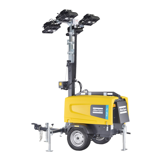
- Page 1 Instruction Manual Instruction Manual for portable generators of lighting towers English HiLight V5+ Motor Kubota Z482 - 1-...
- Page 2 Instruction Manual for portable generators of lighting towers HiLight V5+ Notice This manual solely applies to: Lighting Towers starting from part number BQDXXXXXX. No. 1028 9252 36 - 12/2021 Ed. 00 Web-site: http://www.atlascopco.com...
- Page 3 The effectiveness of these warranties is conditioned to immediate written communication of the defect verified by the Buyer to Atlas Copco, and any intervention on the product or equipment by the Buyer or third parties must not be done, under penalty of voiding the warranty.
- Page 4 Negligence in maintenance or changes to the machine setup may result in risk of major accidents, including the risk of fires. Despite our best efforts to ensure the accuracy of the information in this manual, Atlas Copco does not take any responsibility for eventual errors.
-
Page 5: Table Of Contents
Before you start using the machine, please carefully read the instructions below. While every effort has been made to ensure that the information in this manual is correct, Atlas Copco cannot be held responsible for possible errors. Atlas Copco reserves the right to make changes without prior notice. -
Page 6: Safety Precautions For Portable
Read these instructions carefully and strictly comply with them before moving, lifting, using and maintaining or repairing the machine. Introduction Atlas Copco policy is based on the supply of effective, safe Specialization level 2: Mechanic technician – putting people at risk of electric, mechanic or chemical and reliable products to its clients. - Page 7 If any instruction in this manual is not in compliance with Machines and the equipment should always be Take all necessary precautions against fires. Be local laws, the safer recommendations should be applied. clean, i.e. free of oil, dust or other residues. careful when handling fuel, oil and antifreeze fluid, since these substances are flammable.
- Page 8 Safety standards during transport air outlets and transmission cooling system is not reused. If this air circulates, it may cause the and installation. machine to overheat; and if it enters the combustion To lift the machine, all loose or hinged parts must be zone, it will reduce engine power.
- Page 9 Safety standards during use and to the maintenance table. – above 95 dB(A): warning(s) sign(s) at entrance(s) should have the additional recommendation Attach guards to all moving or rotating parts which operation. that even occasional visitors must use hearing are not duly protected and may present risks to When using the machine in environments with fire protective equipment (PPE), personnel.
- Page 10 The door can however, invisible dust does not indicate the absence be kept open for a short period, only in case of e.g. Parts must be replaced by genuine Atlas Copco spare of more dangerous particles in the air. inspection or adjustment.
- Page 11 Use only lubricants recommended or approved by Atlas Copco or by the machine manufacturer. Ensure the selected lubricants comply with safety regulations, especially those relating to the risk of explosion or fire, and the possibility of decomposition or creation of hazardous gases.
- Page 12 Safety when using tools Therefore: – never smoke near batteries charging or recently charged Use the right tool for each task. By knowing which tool batteries, to use and its limitations, many accidents can be avoided. – never cut off voltage circuits at the battery terminals, Some special maintenance tools are available for specific since it usually causes a spark.
-
Page 13: Main Parts
Main parts Cooler Cubicle Fuel tank Lamp Column Engine Mast Ceiling Battery Door Frame Undercarriage Drawbar Support/ stand - 13-... -
Page 14: Safety Information
Contact with overhead power WARNING mast, stop immediately, move away from the lines will cause serious injury or equipment and contact Atlas Copco. death. Danger of crushing. Do not place the lighting tower – Make sure the trailer is properly grounded, in When operating or working on under the power lines. -
Page 15: Motor Safety
Motor safety Operator safety DANGER: Choking hazard. WARNING DANGER: – Operate the engine outdoors Severe burns hazard. Explosion hazard. and keep away from the engine exhaust. Before handling the lights, let – Keep the engine, fuel, and them cool for 15 minutes. –... -
Page 16: Service Safety
Service safety Before maintenance • Keep your hands, feet and loose clothing away from moving parts of the engine and generator. • Keep the lighting tower and all its components clean. WARNING DANGER: • Keep the labels legible. Replace damaged or missing labels. -
Page 17: Labels
Labels The labels provide instructions and information. They also warn of dangers. For convenience and safety, keep all labels legible, replacing them when damaged or missing. (Replacement labels are available at the factory.) Sample labels and their descriptions are provided in Table 1.1. Figure 1.1 Label location (1028925098) - 17-... - Page 18 Table 1.1 Samples of labels and descriptions Label Description Label Description 1028 9250 03 Electric Shock Warning Label 1079 990 3 61 Warning label (do not wash) 1028 9250 08 Electric Panel instruction Label 0690 9110 03 Flammable liquid Label - 18-...
- Page 19 Label Description Label Description 1028 7542 07 1028 9252 93 Diesel label Bar Instruction Label 1028 8676 02 1028 9252 94 Lamp radiation label Steel cable instruction label - 19 -...
- Page 20 Label Description Label Description 1028 8676 00 0690 1132 01 Electric Lines Label Atlas Copco logo 1028 9250 10 1094 3147 00 Maintenance Kit Label HiLight V5+ label - 20 -...
- Page 21 Label Description Label Description 1028 9250 98 1028 9250 02 Rolling Instruction Label HiLight V5+ Label Kit Grounding label - 21 -...
-
Page 22: Tow Bar Coupling
Tow bar coupling Eyebolt When the lighting tower leaves the factory, the tow bar is set to use the eyebolt by means of a hooked vehicle. Loose parts During transport, the parts below will be disassembled. – Drawbar with tow bar coupling –... -
Page 23: Lighting Fixture Wiring
Lighting fixture wiring Coiled wire - Brown - Phase Lamp 1 – cable 51 Coiled wire - Blue - Neutral Lamp 1 – cable 52 Lamp 1 Coiled wire - Brown - Phase Lamp 2 – cable 53 Lamp 2 Coiled wire - Blue - Neutral Lamp 2 –... -
Page 24: Operation ������������������������������������������������ 24 Maintenance
Operation Safety Towing and lifting Before operating the lighting tower, read and familiarize Before towing yourself with this instruction manual. Before towing, prepare the lighting tower as follows. Read and follow all safety instructions (see page 8). Lower the lighting tower: WARNING Check if the mast of the lighting tower is lowered and secured with the rotation lock. -
Page 25: During Towing
Inspect the tow bar coupling and coupling for wear After towing Lifting and damage. Replace or repair it, if required. Loosen the vehicle’s tow bar coupling as follows: The lighting tower can be lifted by means of the hoisting Check if the rear and side stands are up, the eye or grooves of the forklift mounted on the hoisting Locate the leveling stand on the trailer drawbar at stabilizers are retracted and all is secured with... -
Page 26: Location
Figure 3.2 Hoisting Eye and Forklift Slots Location • For the best possible light coverage, place the lighting tower at the same level as the area to be illuminated, or higher. • To reduce the risk of personal injury, make sure that the surrounding area is in good condition and free of debris. -
Page 27: Installation
Installation Pull the locking pin on the stand and rotate it down Press the button when done. until the locking pin engages. Do not lower the stand Make sure the trailer wheels are locked or yet. with shims applied. Leveling the trailer Repeat the previous two steps for the other stabilizer, Level the trailer and extend the stabilizers Before raising and extending the lighting tower mast, the... - Page 28 1 – Ratchet mounted to the mast Figure 3.3 Grounding beam 2 – Rotation Lock Figure 3.5 Lifting the tower - 28-...
-
Page 29: Lowering The Tower ���������������������������������� 29 Dimensional
Lowering the tower Before moving or storing the lighting tower, lower the mast and lock it in place. To lower the tower, refer to Figure 3.6 and follow the instructions below. 1 - Switches Turn off the tower lights and the engine. To increase the service life of the lamp, allow the lights to cool for 15 minutes before continuing. -
Page 30: Engine Operation
Engine operation • Do not start the engine while this indicator is on. WARNING • Start the engine immediately after the light goes out. Starting the engine The engine may overheat and damage the When the glow plug indicator light is off, turn and Before starting the engine: starter. -
Page 31: Automatic Engine Shutdown
Lamps not switching on Turn off the engine Lights To turn off the engine: If the lamps do not switch on when power is applied, make Turning the lights on Turn off the lights and external devices connected to sure that the appropriate circuit breakers are set to ON. If To turn the lights on, first switch the main circuit breaker the power receptacle. - Page 32 Spotlight lux level - HiLight V5 + Lamps Rotation angle Tilting angle Case Angle Lamp 1 Lamp 2 Lamp 3 Lamp 4 Tilting Rotation Tilting Rotation Tilting 80-70 80-70 80-70 80-70 Rotation -180 Tilting Rotation - 32-...
- Page 33 Case 1 Case 2 Average Lux: 23 Average Lux: 23 4000 m² 3600 m² - 33-...
- Page 34 Case 1 Case 2 Average Lux: 20 Average Lux: 33 5000 m² 2500 m² Lux level - 34-...
-
Page 35: Daily Inspection
Maintenance Daily inspection Engine maintenance Lamp position When the lighting tower is used regularly, the following For engine related maintenance and repairs, refer to the Transport method items should be checked daily: engine instruction manual. • Horizontal position. • Check fluid levels and look for leaks. Spare parts Tilting •... - Page 36 3002 6095 30 for the most important subassemblies, Atlas Copco has developed maintenance kits that combine all wear parts. These maintenance kits offer the benefits of the original parts, save on management costs and are offered at reduced prices, compared to the individual components. Refer to the parts list for more information on the contents of the maintenance kit.
- Page 37 Check the rubber hoses Check the emergency stop Clean radiator Replace the air filter element Check/replace the safety cartridge Inspection by Atlas Copco service technician Inspect the starter Inspect the water pump Inspect alternator Check the engine safety devices Check valve in the fuel return line (for injection system)
-
Page 38: Technical Specifications
Technical specifications Technical specifications for HiLight V5+ units Readings on indicating instruments Indicator Reading Unit Ammeter L3 (P3) Less than the max. rated value Voltmeter (P4) Less than the max. rated value Switches setting Switch Function Unit Engine oil pressure Total stop 0.5 bar Engine coolant temperature... - Page 39 HiLight V5+ Limits 2) Maximum ambient temperature ......................50°C Maximum height ............................ 3500 m Maximum relative humidity ........................85% Minimum starting temperature ......................-10°C Performance data 2) 3) 5) Rated active power (4 lamps) ........................ 1.5 kW Rated active power (4 lamps + sockets) 3.8 kW Rated power factor (with 4 lamps) ......................
- Page 40 HiLight V5+ Design data 4) Alternador Standard ..............................EN50081-1 ............................... EN50082-1 Manufacturer ............................Mecc Alte Model ..............................LT3N-75 Rated outlet, temperature increase of class H ..................4,5 kVA Protection level ............................IP 21 Engine 4) Protection level ............................IP 21 Standard ..............................
- Page 41 HiLight V5+ Speed control ............................mechanical Electrical system ............................ 12 VCC Emission compliance ..........................no emissions Current circuit Circuit breaker, 230V Number of poles ............................. 1 Notes (1) Reference conditions for engine performance according to ISO 3046-1. (2) Refer to rated capacity reduction diagram or consult factory for other conditions. (3) Under reference conditions, unless otherwise stated.
- Page 42 Normal capacity reduction Lighting Tower (%) LED 60Hz To use the lighting tower in conditions other than those specified, please contact Atlas Copco. - 42-...
- Page 43 Electric Diagrams Applicable for V5+, ECU engine circuit Electric diagram - motor circuit, 1028 9251 04, sheet 01 - 43-...
- Page 44 Applicable for V5+, ECU control circuit Preheat Start B(30) BR(AC) R1(19) C(17) R2(50) Electric diagram - motor circuit, 1028 9251 04, sheet 02 - 44-...
- Page 45 Applicable for V5+, ECU control circuit Speed Speed Speed Sensor Sensor Sensor Warning Water temp. Sensor Signal +12V +BP 12V -BP 0V, power ground Solenoid- Solenoid+ IG-SW Lamp ST-SW signal -S10 -B11 All materials supplied are in compliance with the requirements of the List of Prohibited Substances Electric diagram - motor circuit, 1028 9251 04, sheet 03 - 45-...
- Page 46 Applicable for HILIGHT V5+, AC power circuit 220V 60Hz for Brazilian socket All materials supplied are in compliance with the requirements of the List of Prohibited Substances Notes, 1. Wires should comply with the Brazilian standards. Electric diagram - motor circuit, 1028 9251 04, sheet 04 - 46-...
- Page 47 Applicable for V5+, LED AC lamp circuit 220V 60Hz for Brazilian socket Notes, 1. Wires should comply with the Brazilian standards. All materials supplied are in compliance with the requirements of the List of Prohibited Substances Electric diagram - motor circuit, 1028 9251 04, sheet 05 - 47-...
- Page 48 Applicable for HILIGHT V5+, AC power circuit 120V 60Hz for Brazilian socket All materials supplied are in compliance with the requirements of the List of Prohibited Substances Notes, 1. Wires should comply with the Brazilian standards. Electric diagram - motor circuit, 1028 9251 04, sheet 06 - 48-...
- Page 49 Applicable for V5+, LED AC lamp circuit 120V 60Hz for Brazilian socket Notes, 1. Wires should comply with the Brazilian standards. All materials supplied are in compliance with the requirements of the List of Prohibited Substances Electric diagram - motor circuit, 1028 9251 04, sheet 07 - 49-...
- Page 50 Electric diagram - alternator connections, sheet 01 - 50-...
- Page 51 Electric diagram - alternator connections, sheet 02 - 51-...
- Page 52 Dimensional 1175 E=1265 Lifting eye(Ø50) Service door Cleaning Cooler Cooling Air Inlet Emergency Stop Data Plate Cooling Air F=1421 Outlet FRAME DRAIN 1081 Exhaust Air Outlet I=1939 K=966 H=934 B=1180 A=2905 Maintenance Space ( 1 : 10 ) 2850 Center of Gravity Ø64 R697 R697...
- Page 53 J=2392(MAX) 1591 - 53 -...
- Page 54 1175 1265 Lifting eye(Ø50) Service door Cleaning Cooler Cooling Air Inlet Emergency Stop Data Plate Cooling Air R1223 Outlet Exhaust Air Outlet FRAME DRAIN E=1162 1775 B=1332 F=1487 A = 2905 Maintenance Space ( 1 : 10 ) 2850 Center of Gravity Ø64 R697 R697...
- Page 55 1364 H = 2392(MAX) - 55 -...
- Page 56 NOTES...
- Page 57 NOTES...
- Page 58 NOTES...
- Page 59 NOTES...
- Page 60 NOTES...
- Page 61 NOTES...
- Page 62 NOTES...
- Page 63 Atlas Copco Brasil Ltda. - Compressor Technique Alameda Araguaia, 2700 - Tamboré - Barueri - SP - CEP 06455-000 Phone: (11) 3478-8700 - Fax: (11) 4195-7090 CNPJ: 57.029.431/0001-06 Visit us at www.atlascopco.com.br...
Need help?
Do you have a question about the HiLight V5+ and is the answer not in the manual?
Questions and answers