
Related Manuals for Atlas Copco HiLight B6+ Kd ESF


Summary of Contents for Atlas Copco HiLight B6+ Kd ESF
- Page 1 Instruction Manual User and maintenance manual for light towers English HiLight B6+ Kd ESF Z482...
- Page 3 HiLight B6+ Kd ESF User and maintenance manual for light towers User and maintenance manual .............. 5 Circuit diagrams ..................93 Original instructions Printed matter N° 2960 7090 00 ATLAS COPCO - POWER AND FLOW DIVISION www.atlascopco.com 09/2021...
- Page 4 While every effort has been made to ensure that the information in this manual is correct, Atlas Copco does not assume responsibility for possible errors. Copyright 2021, Grupos Electrógenos Europa, S.A.U., Zaragoza, Spain. Any unauthorized use or copying of the contents or any part thereof is prohibited.
-
Page 5: Table Of Contents
Please read the following instructions carefully before starting to use your machine. While every effort has been made to ensure that the information in this manual is correct, Atlas Copco does not assume responsibility for possible errors. Atlas Copco reserves the right to make changes without prior notice. - Page 6 Setting the Smart Mast™ 5.5.3 Servicing air filter engine....60 7.4.3 Auto start with photocell on mast controller ..........44 head ...........73 5.5.4 Air cooling circuit ........61 4.5.1 Push buttons ........44 7.4.4 Auto tilt ..........75 5.5.5 Replacing the LEDs ......61 4.5.2 Module display ........45 7.4.5 MSA connector........75 5.5.6...
- Page 7 10.5 Dimension drawing......90 10.6 Conversion list of SI units into British units ........92 10.7 Data plate..........92 - 7 -...
-
Page 8: Safety Precautions
The policy of Atlas Copco is to provide the users of their Atlas Copco equipment. It is the responsibility of unsafe operating conditions. Take necessary steps to equipment with safe, reliable and efficient products. -
Page 9: General Safety Precautions
The manufacturer does not accept any liability for any All regulating and safety devices shall be General safety precautions damage arising from the use of non-original parts and for maintained with due care to ensure that they The owner is responsible for maintaining the unit in modifications, additions or conversions made without function properly. -
Page 10: Safety During Transport And Installation
If required, a floor is not level or can vary in inclination, consult lifting beam shall be applied between hoist and Atlas Copco. To lift a unit, all loose or pivoting parts, e.g. doors and load. -
Page 11: Safety During Use And Operation
- above 85 dB(A): room to be classified as a noise- appropriate protection, at least safety glasses, for otherwise stated in the Atlas Copco Instruction hazardous area and an obvious warning shall be the operator as well as for any bystander. Do not Book (AIB). - Page 12 15 Safety shoes should be compulsory in any 22 Whenever an abnormal condition arises, e.g. 28 When deploying the light tower mast, keep in mind workshop and if there is a risk, however small, of excessive vibration, noise, odour, etc., switch the following safety precautions: falling objects, wearing of a safety helmet should be circuit breakers to OFF and stop the engine.
-
Page 13: Safety During Maintenance And Repair
Parts shall only be replaced by genuine Atlas Copco before carrying out such operations. Disconnect the that the oil pump and the fan function properly. -
Page 14: Tool Applications Safety
Tool applications safety Battery safety precautions Apply the proper tool for each job. With the knowledge When servicing batteries, always wear protecting of correct tool use and knowing the limitations of tools, clothing and glasses. along with some common sense, many accidents can be The electrolyte in batteries is a sulphuric acid prevented. -
Page 15: Main Parts
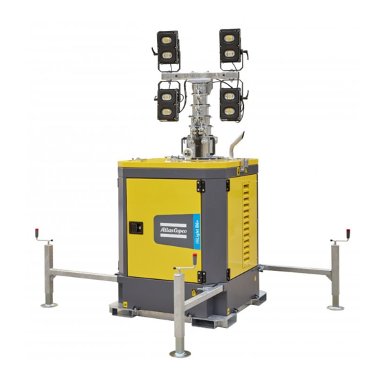
Main parts General description The HiLight B6+ light tower provides a spillage free frame and 4 LED floodlights of 350 W each. The HiLight B6+ is very useful for construction sites where no electricity nor lighting is available. Control panel Data plate Earth pin (optional) Floodlights... -
Page 16: Markings
Markings Use PAROIL E only. Markings provide instructions and information. They also warn of hazards. For convenience and safety, Indicates that the mast should not be keep all markings in legible condition, replacing them extended near electric wires. when damaged or missing. Replacement markings are Indicates the sound power level in available from the factory. - Page 17 Indicates Arc flash and shock Indicates the earthing connections on hazard. Follow all requirements the light tower. in NFPA 70E for safe work practices and for Personal Protective Equipment. Indicates the danger of touching rotating parts of the unit. Warning and information label on Arc flash hazard and appropriate PPE requirement.
-
Page 18: Mechanical Features
Mechanical features 2.3.4 Bodywork 2.3.7 Filler caps The alternator, the engine, the cooling system, etc. are The fuel filler cap and oil filler cap are located inside The mechanical features described in this chapter are enclosed in a sound-insulated bodywork that can be the unit. -
Page 19: Electrical Features
Electrical features A1 ..Lc1003™ digital controller S20..REMOTE/ON/OFF switch Position : REMOTE START, for Auto The electrical features described in this chapter are F10 ..Fuse 10A Photocell or weekly timer standard provided on this light tower. For all optional The fuse trips when the current from the start option electrical features, see chapter “Overview of the... - Page 20 2.4.1.2 Units with Smart Mast™ A1 ..Digital controller Features of the controller The dedicated controller provides unique features and F10 ..Fuse 10A Overview control panel benefits for light tower application, such as: The fuse trips when the current from the To operate the light tower a control panel is installed.
-
Page 21: Emergency Stop Button
2.4.2 Emergency stop button S2 ..Emergency stop button Push the button to stop the light tower in case of an emergency. When the button is pressed, it must be unlocked by rotating it clockwise, before the light tower can be restarted. -
Page 22: Installation And Connection
Installation and connection To be able to lift the light tower by means of a forklift, Lifting Positioning and transport forklift slots (2) are provided in the frame at each side The lifting eye (1), to lift the light tower by means of The operator is expected to apply all of the unit. - Page 23 4. Once the stabilizers (3) have been extended, 6. Once the light tower is correctly positioned, install Check the levels (5) on top of the release the locking pin (1) to lock them in a suitable earthing (e.g. the optional earth pin (6)) light tower to ensure that the unit is position.
-
Page 24: Positioning For Transport
2. Use the handle at the top of each foot to retract the 3.2.2 Positioning for transport 4 feet (2). 1. Make sure the mast is lowered completely and turned 90° (1). See also chapter “Lowering the mast” on page 34. Adjust the height of the supporting feet gradually in order to ensure the stability of the unit. -
Page 25: Transportation And Positioning Of The
3.2.3 Transportation and positioning Schematic overview: of the light tower onto vehicles Due to its compact and optimized design, the Transport of one single unit: HiLight B6+ offers a great transport efficiency. The light tower can be easily lifted and moved to difficult areas thanks to its central lifting eye and double forklift pockets in its frame. -
Page 26: Installation
Atlas The light tower is wired for a TN- Copco dealer. Consult Atlas Copco for measures against the adverse system to IEC 364-3, i.e. one point in influence of non-linear loads. the power source directly earthed - 3.3.2... -
Page 27: Operating Instructions
Operating instructions Before starting Operating the light tower – Perform all daily checks and maintenance as Carefully read follow In your own interest, always strictly specified in the “Maintenance schedule” on page sequence operating observe relevant safety instructions in the Engine's manual instructions. -
Page 28: Before The Engine Is Started
4.2.1 Before the engine is started 4.2.1.2 Units with Smart Mast™ 4.2.2 Starting the engine 1. Before starting the engine, check that all the 4.2.1.1 Units with Lc1003™ controller 4.2.2.1 Units with Lc1003™ controller automatic switches (general ELCB, sockets 1. Before starting the engine, check that all the 1. -
Page 29: Positioning The Floodlights
3. Select one of the configured positions and tighten 4.2.2.2 Units with Smart Mast™ 4.2.3 Positioning the floodlights the screw. 1. Push the START button (2) on the controller. Rotation 4. Tighten the central handle again. 2. Once the machine starts, the controller will check 1. -
Page 30: Extending The Mast
4.2.4 Extending the mast optional “Photocell” provided and the Auto start lighting level option is enabled, the mast will be extended automatically. Lc1003 Before extending the mast, and in particular when the Auto start lighting level option is enabled, make sure that the lighting tower is AUTO properly positioned, away from overhead power cables or other... -
Page 31: Rotating The Mast
4.2.4.2 Units with Smart Mast™ 4.2.6 Switching on/off the floodlights 4.2.5 Rotating the mast 1. Switch ON the main circuit breaker (Q1) and 4.2.6.1 Switching on the floodlights 1. Unlock the locking pin (1) of the mast (located on make sure all other breakers are switched OFF manually its rotating base) and rotate the light tower using (Q2-6). - Page 32 4.2.6.2 Switching off the floodlights Units with Smart Mast™ When the light tower is connected to manually the mains (“External power input 1. Select OFF (2) in the Lighting menu of the To switch the lights off manually, follow the (230 VAC), with battery charger”...
- Page 33 3. Switch ON the 4 circuit breakers (Q2-5) (2). 4.2.6.3 Switching on/off the floodlights When the light tower is connected to automatically the mains (“External power input (230 VAC), with battery charger” Units with Lc1003™ option, S10 in position 2, see section 7.4.6.) all lights will ignite at the Only applicable with timer or same time, as soon as circuit...
-
Page 34: Lowering The Mast
4.2.7 Lowering the mast Mind your head while lowering the 4.2.7.1 Units with Lc1003™ mast! 1. If the floodlights are not to be used again, lower When lowering the mast, check that the mast using the DOWN button on the control the power cord on the mast (spiral panel (1). -
Page 35: Stopping The Engine
6. If the optional External power input (230 VAC) is 4.2.8 Stopping the engine 4.2.8.2 Units with Smart Mast™ installed, switch S10 to O (OFF) (5). See also 1. Lower the mast. See section 4.2.7. Follow the instructions below to switch the engine off chapter “External power input (230 VAC), with correctly: 2. - Page 36 3. Push the STOP button (3) on the control module Should an emergency arise, it is also to go into cool down. possible to stop the machine by 4. After cool down, which takes approx. 30 sec., pressing the EMERGENCY 'STOP' push the POWER button (1) on the control button (6).
-
Page 37: Connecting Appliances
4. Switch on circuit breaker Q6 (2). Connecting appliances Avoid long low-load periods (< 30%). In this case, an output Keep in mind that this machine is a drop and higher oil consumption of light tower, not a generator set! the engine could occur. -
Page 38: Setting The Lc1003™ Controller
Setting the Lc1003™ controller Following LEDs are used on the Lc1003™: AUTO: Is used to activate Auto Controller settings should only be mode. performed by a qualified technician. It is also used for floodlight operation: 4.4.1 Push button and LED functions –... -
Page 39: Module Display
4.4.2 Module display 4.4.3 Icon overview Display Description 4.4.2.1 Home page 4.4.3.1 Instrumentation icons Fuel sender instrumentation screen The home page is the page displayed when no other Display Description page has been selected: The default home page which Appears when the event log is being displayed displays Generator voltage and the Auto Run icon... - Page 40 4.4.3.2 Active configuration 4.4.3.4 Mode icons 4.4.3.5 Light output icons Display Description Display Description Display Description Appears when the corresponding Appears when the main Appears when the engine is at rest light output has been configured configuration is selected. and the unit is in stop mode. and is not active.
-
Page 41: Navigation Menu
To view the event log: 4.4.4 Navigation menu Display Description To enter the navigation menu, press both the UP and 1. Press the UP and DOWN buttons simultaneously DOWN buttons simultaneously. Event Log to display the navigation menu. To navigate to the desired page, select the 2. -
Page 42: Setting The Lc1003™ Scheduler
4.4.6 Setting the Lc1003™ scheduler 4.4.6.2 Schedule period 4.4.6.4 Run mode Choose between a Weekly, Monthly or Daily To access the scheduler editor, navigate to one of the repetition of the schedule. scheduler pages and press and hold the STOP/ RESET MODE button. - Page 43 4.4.6.6 Start day 4.4.6.8 Duration Select the day of the week: – 1= Monday – 2= Tuesday – 3= Wednesday – 4= Thursday – 5= Friday – 6= Saturday – 7= Sunday 4.4.6.7 Start week Select the week of the month (1, 2, 3, 4). - 43 -...
-
Page 44: Setting The Smart Mast™ Controller
Setting the Smart Mast™ controller STOP: This button will initiate the ALARMS: This button will enter Controller settings should only be cool down/stopping sequences if the the Alarms View when not already performed by a qualified technician. controller is in normal running in the Alarms View, or when Smart Mast™... -
Page 45: Module Display
4.5.2 Module display 4.5.2.1 Main view Operation The main view is the page displayed when no other In this tab, the functioning mode can be selected: Main data is always such as fuel consumption, Smart page has been selected. Mast™ status and working mode is always shown. –... -
Page 46: Icon Overview
4.5.3 Icon overview 4.5.3.2 Mode icons 4.5.3.4 Alarm icons Display Description 4.5.3.1 Instrumentation icons Display Description Appears when the unit is set to Active and acknowledged alarm. Display Description operate in manual mode. Appears when Automast is active Active and not-acknowledged non- Appears when the unit is set to shutdown alarm. -
Page 47: Lighting Menu
4.5.4 Lighting menu 4.5.4.2 Light 4.5.4.3 Lighting level This setting refers to the starting mode of the The target lighting level is selected with 3 icons To enter the lighting menu, use the NAVIGATION floodlight. representing: buttons on the main screen and press ENTER to select. -
Page 48: Mast Stability Menu
4.5.5 Mast stability menu 4.5.5.1 Auto mast 4.5.5.4 Mast blocked In this menu, the user can enable or disable the auto This indicates that the mast is blocked due to a high To enter the mast stability menu, use the mast feature. -
Page 49: Scheduler Menu
Fleetlink module has been installed in the light tower. reacts equally as to the soft alarm. If the The scheduler can contain up to 70 events, with Fleetlink is an Atlas Copco GPRS/GPS module that oscillations decrease or do not reach the safety multiple events working simultaneously. -
Page 50: Periodic Maintenance
1636 3105 95 For the most important sub-assemblies, Atlas Copco has developed service kits that combine all wear parts. These service kits offer you the benefits of genuine parts, save on administration costs and are offered at reduced price, compared to the loose components. Refer to the parts list for more information on the contents of the service kits. - Page 51 50 hours after Maintenance schedule Daily Every 100 hours Every 600 hours Yearly start-up Service pack 1636 3105 95 Inspect/Adjust fan/alternator belt Replace alternator belt Check/test emergency stop (13) Clean radiator (1) Drain condensate and water from spillage-free frame (8) Check for leaks in engine-, air-, oil-, or fuel system (8) Hoses and clamps - Inspect/Replace Check electrical system cables for wear...
- Page 52 Grease cylinder rotule Change hydraulic oil General Inspection by Atlas Copco Service technician Light towers in stand-by application have to be tested on a regular basis. At least once a month the engine should run for minimum 30 minutes at a high load (50% - 70%) that the engine reaches its operating temperature.
-
Page 53: Precautions
The order number of the Service Packs are listed in (6) See section oil specification. engine is running. the Atlas Copco Parts list (ASL). Order Service Packs at your local Atlas Copco dealer. (7) The following part numbers can be ordered from –... -
Page 54: Preventing Low Loads
– Low combustion temperature: this will result in For more info, please contact your Atlas Copco Preventing low loads insufficiently burnt fuel, which will cause diluting Service Center. of the lube oil. Also, unburnt fuel and lube oil can 5.2.1... -
Page 55: Maintenance Of The Alternator
– Do not smoke and maintain a safe distance from Maintenance of the Engine maintenance flames and sparks while maintenance is being alternator procedures carried out and when fuels and solvents are being The alternator does not require any specific general used. -
Page 56: Engine Oil System
4. If the oil level is close to the MIN level indicator, 5.4.2 Engine oil system 5.4.2.1 Engine oil level check top up engine oil to the MAX level indicator. 1. Make sure the light tower is standing level. 2. Switch off the engine and wait several minutes till all engine oil has been collected in the crank housing. - Page 57 5.4.2.2 Changing the engine oil 5.4.2.3 Cleaning the oil filter 1. Start the engine and let it run for a while to warm 1. Remove the oil filter (1). 2. Stop the engine. 3. Remove the plug (1) from the oil drain hose (2). 2.
-
Page 58: Adjustments And Service Procedures
Adjustments and service 5.5.1.1 Electrolyte 5.5.1.3 Recharging a battery Before and after charging a battery, always check the procedures Read safety instructions electrolyte level in each cell; if required, top up with carefully. distilled water only. When charging batteries, each 5.5.1 Battery care cell must be open, i.e. -
Page 59: Replacing The Fuel Filters
– Loosen the hose clamps and remove them from 5.5.1.5 Periodic battery service 5.5.2 Replacing the fuel filters the pre filter (1). – Keep the battery clean and dry. – Unscrew the filter element (2) from the adapter – Keep the electrolyte level at 10 to 15 mm above head. -
Page 60: Servicing Air Filter Engine
Servicing air filter engine 5.5.3.2 Recommendation 5.5.3.4 Replacing the air filter element – Remove the dust trap (1). Clean the trap. The Atlas Copco air filters are 5.5.3.1 Main parts specially designed this – Remove the element (3) from the housing (4). -
Page 61: Air Cooling Circuit
5.5.4 Air cooling circuit 5.5.5 Replacing the LEDs Check every day that none of the air 1. Loosen and remove the 6 screws (1) and remove cooling circuits are clogged with the protection lenses (2) in front of the LEDs. dust or other particles. -
Page 62: Ordering Spare Parts
The viscosity grade should correspond to the ambient temperature and ISO 3448, as follows. Specifications PAROIL PAROIL from Atlas Copco is the ONLY oil tested Engine Type of lubricant and approved for use in all engines built into Atlas Copco compressors, generators and light towers. - Page 63 PAROIL provides wear protection under extreme PAROIL Extra conditions. Powerful oxidation resistance, high PAROIL Extra is a synthetic ultra high performance chemical stability and rust- inhibiting additives help diesel engine oil with a high viscosity-index. Atlas reduce corrosion, even within engines left idle for Copco PAROIL Extra is designed to provide extended periods.
-
Page 64: Checks And Troubleshooting
Checks and Engine troubleshooting troubleshooting Refer to the Engine Operation manual for engine troubleshooting. Never perform a test run with connected power cables. Never Solving controller alarms touch electrical connector without a voltage check. 6.2.1 General When a failure occurs, always If an alarm condition occurs, an icon is displayed in report what you experienced before, the Alarm Icon section of the Lc1003™... -
Page 65: Alarm Overview
6.2.2 Alarm overview 6.2.2.1 Warning alarm icons Warnings are non-critical alarm conditions and do not affect the operation of the light tower, they serve to draw the operators attention to an undesirable condition. By default, warning alarms are self-resetting when the fault condition is removed. Display Description Reason... - Page 66 Display Description Reason The generator output frequency has fallen below the pre-set pre-alarm setting after the Safety Generator Under Frequency On timer has expired. Generator Over Frequency The generator output frequency has risen above the pre-set pre-alarm setting. Immediate Over Current The measured current has risen above the configured trip level.
- Page 67 6.2.2.2 Electrical trip alarm icons Electrical trips are latching and stop the light tower, but in a controlled manner. On initiation of the electrical trip condition the Lc1003™ module de-energises all the ‘Light Output’ outputs to remove the load from the light tower. Once this has occurred the Lc1003™ module starts the Cooling timer and allows the engine to cool off- load before shutting down the engine.
- Page 68 6.2.2.3 Shutdown alarm icons Shutdown alarms are latching and immediately stop the light tower. On initiation of the shutdown condition the Lc1003™ module de-energises all the ‘Light Output’ outputs to remove the load from the light tower. Once this has occurred, the Lc1003™ module shuts the light tower down immediately to prevent further damage. The alarm must be accepted and cleared, and the fault removed to reset the Lc1003™...
- Page 69 Display Description Reason Battery Over Voltage The DC supply has risen above the high volts setting level. The generator output voltage has fallen below the pre-set pre-alarm setting after the Safety On Generator Under Voltage timer has expired Generator Over Voltage The generator output voltage has risen above the pre-set pre-alarm setting.
- Page 70 Display Description Reason Oil Filter Maintenance Alarm Maintenance due for oil filter. Air Filter Maintenance Alarm Maintenance due for air filter Fuel Filter Maintenance Alarm Maintenance due for fuel filter. - 70 -...
-
Page 71: Options Available For Hilight B6+ Units
Options available for Description of the Overview of the electrical mechanical options options HiLight B6+ units The following electrical options are available: 7.2.1 Spark arrester Overview of the mechanical – Power output connections (230V/16A) options – Power output connections (120V/20A) The following mechanical options are available: –... -
Page 72: Description Of The Electrical Options
If the power demand exceeds 2700 W, the Lc1003™ Description of the electrical X1 ..1-phase outlet socket (230 V) controller will stop the HiLight B6+ (high power Provides phase L, neutral and earthing. options shutdown). 3 different versions are available: 7.4.1 Power output connections The power of the hydraulic pump... -
Page 73: Power Output Connections
7.4.2 Power output connections 7.4.3 Auto start with photocell on (120V/20A) mast head Following 120V sockets are also available as an option: – Socket GFCI Duplex 20A P7.1 – Twist Lock Socket 60Hz 20A Lc1003 AUTO The photocell measures the luminosity and can be activated by sunlight. - Page 74 There are 2 blinking levels: Setting the sensitivity regulator ASM (Auto Rise and Lower Safety Mast) The photocell sensitivity regulator is used for – Level 1: slow blinking The ASM option provides the possibility to not only regulating the luminosity sensitivity level of the switch on/off the floodlights automatically, but also The photocell detects there is enough light, photocell.
-
Page 75: Auto Tilt
To enable automatic mast operation, proceed as 7.4.4 Auto tilt 7.4.5 MSA connector follows: The auto tilt option allows to set the inclination angle The MSA connector is located in the cubicle and of the floodlights via the control panel. allows remote emergency stops. -
Page 76: External Power Input (230 Vac), With Battery Charger
7.4.6 External power input (230 VAC), 7.4.7 Override fuel shutdown 7.4.8 Earth pin with battery charger With this option installed, the floodlights will switch The earth pin (1), to be connected to the light tower’s off automatically one by one when the unit is running earth terminal is located at the bottom of the frame on Overview out of fuel (<... -
Page 77: Battery Switch
7.4.9 Battery switch 7.4.10 Fleetlink The battery switch (1) is installed near the battery and Fleetlink is an intelligent telematics system that helps allows to disconnect the battery power. optimize fleet usage, reduce maintenance cost, ultimately saving time and money. It allows to manage the unit conveniently wherever it is, always helping with the latest fleet information. -
Page 78: Storage Of The Light Tower
Storage of the light tower Storage Preparing for operation after storage – Store the light tower horizontally in a dry, frost- free room which is well ventilated. Before operating the light tower again, remove the wrapping, VCI paper and silica gel bags and check the –... -
Page 79: Disposal
(for example sand, sawdust) and recyclable materials. dispose it according the applicable local disposal Your Atlas Copco light tower mainly consists of regulations. Do not drain into the sewage system or metallic materials, that can be re-melted in steelworks surface water. -
Page 80: Technical Specifications Of The Light Tower
Technical specifications of the light tower 10.1 Technical specifications of the engine/alternator/unit 50 Hz (230V - 1ph) 60 Hz (120V - 1ph) Rated frequency 50 Hz 60 Hz Reference conditions 1) Rated speed 1500 rpm 1800 rpm Generator service duty Absolute air inlet pressure 1 bar(a) 1 bar(a) - Page 81 Single step load capability 100% 100% 2.58 kW 2.85 kW Mode of operation Application data Site land use land use Operation single single Start-up and control mode manual/auto manual/auto Start-up time unspecified unspecified Mobility/Config. acc. to ISO 8528-1:1993 transportable transportable Mounting fully resilient fully resilient...
- Page 82 Insulation stator class Insulation rotor class Number of wires Circuit-breaker 1ph: Electrical power circuit Number of poles Thermal release (lt) Fault current protection, residual current release, Idn 0.03 A 0.03 A Circuit-breaker 1ph: Number of poles Thermal release (lt) Magnetic release (lm) C curve C curve Circuit-breaker 1ph:...
- Page 83 Notes Reference conditions for engine performance to ISO 3046-1. See derating diagram in the graph section or consult the factory for other conditions. At reference conditions unless otherwise stated. Rating definition (ISO 8528-1): LTP: Limited Time Power is the maximum electrical power which a generating set is capable of delivering (at variable load), in the event of a utility power failure (for up to 500 hours per year of which a maximum of 300 hours is continuous running).
- Page 84 1500 84.0 2000 78.9 2500 74.1 3000 69.6 3500 65.4 For use of the light tower outside these conditions, please contact Atlas Copco. Derating table (in %) 60 Hz - Humidity 30% Temperature Height (°C) (kPa) 101.3 110% 109% 107%...
-
Page 85: 10.2 Critical Bolt Connections
10.2 Critical bolt connections Allowed Applicable Torque Additional Parts to assembly Dimension Quality deviation standard (Nm) treatment (Nm) Rotation system (central disc) AC - STD 4369 ± 29 Mast - rotation system AC - STD 4369 ± 5 Rotation system (canopy point) AC - STD 4369 ±... -
Page 86: 10.3 Average Illumination Versus Distance
10.3 Average illumination versus distance Administrative jobs Manual jobs Earth moving - 86 -... -
Page 87: 10.4 Floodlight Lux Level
10.4 Floodlight lux level Lamps Rotation angle Inclination angle Case Angle Lamp 1 Lamp 2 Lamp 3 Lamp 4 Inclination Rotation Inclination Rotation 80-70 80-70 80-70 80-70 Inclination -180 Rotation Inclination Rotation - 87 -... - Page 88 Case 1 Case 2 50 m 60 m Average Lux: 23 Average Lux: 23 4000 m² 3600 m² - 88 -...
- Page 89 Case 3 Case 4 Average Lux: 20 Average Lux: 33 5000 m² 2500 m² Lux level: - 89 -...
- Page 90 10.5 Dimension drawing - 90 -...
- Page 91 - 91 -...
- Page 92 10.6 Conversion list of SI units 10.7 Data plate Name of manufacturer into British units Maximum permitted total weight of the vehicle Machine type 1 bar 14.504 psi Mode of operation 0.035 oz Model number MASA (Kg) 1 kg 2.205 lbs Frequency 1 km/h 0.621 mile/h...
- Page 93 Circuit diagrams - 93 -...
- Page 94 1640 0665 51_01 Applicable for HiLight B6+, Controller Circuit S20 - Configuration (03) 11.1 X11 11.1 REMOTE to Circ.Diagr POWER 11.2 Fuses F1-F2, Current Transfo. 11.2 (03) (04) Lc1003 MKII K115 K114 (04) K120 K114 K115 K100 K115 K114 K116 (06) 40 41 20 21...
- Page 95 Mast up push button Generator control unit Mast down push button Fuel level sensor Spiral cable Capacitor 10µF Connector wire harness Diode Auxiliary terminals Diode Connector lighting Diode MSA 3P connector Preheat resistor Mast down solenoid Fuse 10A DC Fuse 2A DC - Fleetlink (03) Optional Mains connection Battery 12Vdc...
- Page 96 1640 0665 51_02 Applicable for HiLight B6+, Power Circuit Wire size Colour code (03) 230V 50Hz a = 1 mm² 0 = black Mains b = 1.5mm² 1 = brown 230V - 50Hz c = 2.5mm² 2 = red d = 4 mm² 3 = orange e = 6 mm²...
- Page 97 Actuator Controller Capacitor (alternator) F1-F2 Fuses 2A Alternator K101-K104 Light control relay K120 Mains relay Autotilt actuator Pump Earth leakage 25A/30mA Circuit breaker 6A Circuit breaker 6A Circuit breaker 6A Circuit breaker 6A Circuit breaker 10A Circuit Breaker 2A, 2P GENSET/OFF/MAINS switch Autotilt switch up/down Earth leakage test button...
- Page 98 1640 0665 51_03 Applicable for HiLight B6+, Mains Connection (optional) ECU Kubota Wire size Colour code X20 22 16 17 18 19 1 20 2 43 36 41 9 44 21 13 a = 1 mm² 0 = black b = 1.5mm² 1 = brown c = 2.5mm²...
- Page 99 Coolant temperature sensor Speed sensor Fuel stop solenoid Connector wire harness ECU connector - 99 -...
- Page 100 1636 0211 79 Applicable for HiLight B6+, Smart Mast™ Xc2003 (03) 11.1 X1_DI X1_AI X2_DI X2_DO 11.2 11.1 11.2 K114 X11 X11 22 14 40 41 Cubicle Canopy BE-2 RD-1 BE-1 BN-1 BN-2 RD-2 PWM + PWM - (05) IN_5 (08) - Optional MSA connector FM01...
- Page 101 50Hz Mains 230V - 50Hz (03) X8 1 X8 3.1 9-11 (02) (03) 30mA b6 b54 b6 b54 b6 b54 K110 K115 Cubicle Mast b6 b54 b6 b54 W2 U2 - 101 -...
- Page 102 ECU Kubota X20 22 16 17 18 19 1 20 2 43 36 41 9 44 21 13 to Circ.Diagr ENGINE Control Module - 102 -...
- Page 103 Resistor 12kΩ c = 2.5mm² 4 = yellow Controller - Xc2003 Resistor 39Ω d = 4mm² 5 = green Resistor 120Ω e = 6mm² 6 = blue Fuel level sensor Battery switch f = 10mm² 7 = purple Coolant temperature sensor Emergency stop g = 16mm²...
- Page 104 1640 0367 80 Applicable for HiLight B6+, Smart Mast™ OPTION - 03 OPTION - 08 BASIC PART -OP +OP CANAL 60 x 25 OPTION - 11 BASIC PART OPTION - 02A BASIC PART K115 K100 K114 K116 K130 STABILITY CANAL 60 x 25 BASIC PART OPTION - 02A OPTION - 02C...
- Page 105 Options Basic parts smart mast Breaker earth leakage- type AC Breaker earth leakage- type A Power output connections - CEE Power output connections - RIM Power output connections - PIN External power input Battery switch Override fuel shutdown MSA connector Fleet link - 105 -...
- Page 106 KEEP THESE CONNECTIONS FREE FOR USE BY ESF OR CUSTOMER. IN THESE AREAS THE CABLE TRAY IS INTERRUPTED TO FACILITATE CONNECTIONS IN ESF. -X16 - 106 -...
- Page 107 LEFT SIDE RIGHT SIDE NOTE 1 BASIC PART Rear view mm² mm² TUBULAR TUBULAR ORANGE mm² ORANGE mm² TUBULAR TUBULAR NOTE 1 mm² TUBULAR TUBULAR ORANGE mm² ORANGE mm² NOTE 2 TUBULAR TUBULAR NOTE 3 BASIC PART ORANGE mm² ORANGE mm²...
- Page 108 1640 0364 70 Applicable for HiLight B6+, Smart Mast™ COMPONENTS LAYOUT ELECTRICAL CONNECTIONS DETAILS CABLE NAME LABEL spiral cable W10 - CABLE CUT VIEW RD-1 RD-1 BE-2 RD-2 RD-2 BE-2 BE-1 BK-1 BK-1 BE-1 YE/GR BK-2 BK-2 YE/GR BN-2 BN-1 BN-1 BN-2 USE FORK TERMINAL...
- Page 109 Resistor 120Ω Connector female 10P+PE X21..X24 Connector female 3P X31..X34 Connector female 2P X41, X42 Connector female 5P M12 COLISSION SENSOR INCLINATION SENSOR - 109 -...
- Page 110 - 110 -...
- Page 111 A company within the Atlas Copco Group Postal address Phone: +34 902 110 316 V.A.T A50324680 Poligono Pitarco II, Parcela 20 Fax: +34 902 110 318 50450 Muel ZARAGOZA For info, please contact your local Atlas Copco representative Spain www.atlas copco.com p.1(10) - 111 -...
- Page 112 A company within the Atlas Copco Group Postal address Phone: +34 902 110 316 V.A.T A50324680 Poligono Pitarco II, Parcela 20 Fax: +34 902 110 318 50450 Muel ZARAGOZA For info, please contact your local Atlas Copco representative Spain www.atlas copco.com p.2(10) - 112 -...
Need help?
Do you have a question about the HiLight B6+ Kd ESF and is the answer not in the manual?
Questions and answers