Nibe FIGHTER 310P Manual
- Service instructions manual (9 pages) ,
- Installation and maintenance instruction (36 pages) ,
- Installation and maintenance instructions manual (32 pages)
Advertisement
- 1 General
- 2 System description
- 3 Front panel
- 4 Functions on the front panel
- 5 Room temperature
- 6 Maintenance routines
- 7 General points for the installation engineer
- 8 Pipe connections
- 9 Ventilation connection
- 10 Electrical connections
- 11 Commissioning and adjusting
- 12 Setting the automatic heating control system
- 13 Dealing with malfunctions
- 14 Service
- 15 Component locations
- 16 Electrical circuit diagram
- 17 List of components
- 18 Dimensions
- 19 Technical specifications
- 20 Accessories
- 21 Documents / Resources
General
In order to get the ultimate benefit from your heat pump FIGHTER 310P you should read through the For Home Owners section in this Installation and Maintenance Instruction".
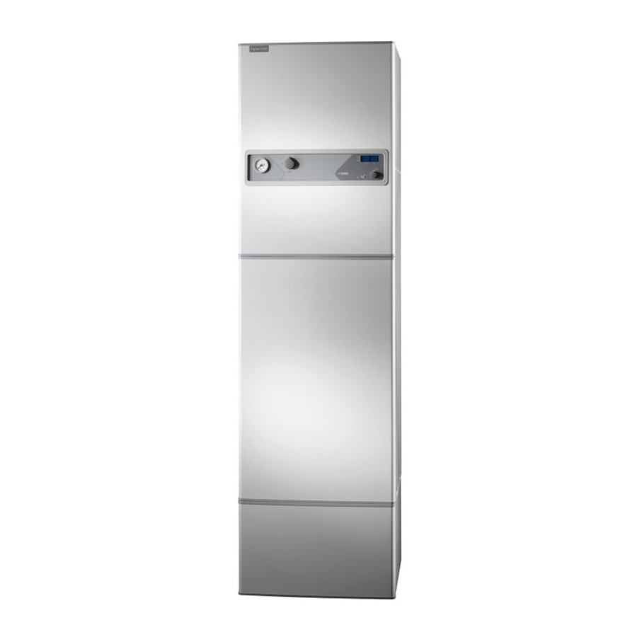
FIGHTER 310P is an exhaust air heat pump. This means that it collects the energy in the ventilation air and uses it for hot water and room heating.
A microprocessor ensures that the heat pump always works efficiently.
FIGHTER 310P is a Swedish-made quality product which will last a long time and run reliably without unpleasant surprises.
To be filled in when the heat pump has been installed
| The serial number (103), should always be stated with all correspondence with NIBE. 089_ _ _ _ _ _ _ _ _ _ _ |
| Installation date |
| Installation engineers |
| Chosen power rating, immersion heater |
| Circulation pump setting |
| Fan rating |
| Selected fan curve |
| Set damper angle |
| Setting "Heating curve selection" |
| Setting "Heating curve offset" |
System description
Principle of operation
FIGHTER 310P comprises an electric boiler with a copper lined water heater and a heat pump which recovers energy from the ventilation air. The recovered energy is supplied to the heat pump. The heat pump must be installed in a ventilation system intended for mechanical exhaust air.
The output of the immersion heater is max 9.0 kW (Supplied output of 8.0 kW). 13,5 kW available as an extra option.
When the exhaust air at room temperature passes through the evaporator, the refrigerant evaporates because of its low boiling point. In this way the heat in the room air is transferred to the refrigerant.
The refrigerant is then compressed in a compressor, causing the temperature to rise considerably.
The warm refrigerant is fed to the condenser, which is in the boiler water. Here the refrigerant gives off its heat to the boiler water, so that its temperature drops and the refrigerant changes state from gas to liquid.
The refrigerant then goes via filters to the expansion valve, where the pressure and temperature are further reduced.
The refrigerant has now completed its circulation and returns to the evaporator.

System diagram

Front panel
Upper (visible) part of the front panel
 part of the front panel")
Lower (hidden) part of the front panel
 part of the front panel")
Functions on the front panel
Visible functions
- Pressure gauge
Here the radiator circuit pressure is displayed. Gauge graduation is 0 - 4 bar. Normal pressure is 0.5 - 1.5 bar. - Power switch
with 3 modes 0 - 1 - R:
0 Heat pump off.
1 Normal mode. All control functions connected.
R Standby. This mode is used during start up and with any operating disruptions. - Indicator lamps
![]()
Upper lamp
Lit Compressor is operational.
Flashing –
Not lit Compressor is not operational.
Centre lamp
Lit Automatic defrosting.
Flashing – Not lit Normal mode.
Lower lamp
Lit Immersion heater is operational.
Flashing Parts of the immersion heater are disabled by an external controller (load monitor, etc).
Not lit Immersion heater is not operational. - Numerical display
In normal mode the boiler temperature is displayed here. The two digits on the left indicate the "channel number" and the two on the right the reading/setting of that channel.
In the event of a malfunction, an error message is displayed alternately with channel number and value. See "Dealing with malfunctions" — "Indications on the numerical display".
NOTE! When switching from Standby mode "R" to normal mode "1" the numerical display can remain dimmed for a brief period. This can also occur at extremely low outdoor temperatures. - Extra hot water
Pressing the "Extra hot water" button raises the boiler temperature to about 60°C, giving increased water capacity for about 24 hours. In this mode, the built-in lamp is constantly lit.
Pressing the button again gives a permanent function which raises temperature of the hot water at regular intervals. In this mode, the built-in lamp flashes.
Pressing the button again resets the above functions. - Heating curve offset
With the "Heating curve offset" button you can change the offset of the heating curve and thus the room temperature.

Hidden functions
- Operating mode indications
![]()
The two lamps next to the operating mode selector indicate the chosen operating mode. This should not be confused with the indicating lamps in the numerical display.
Uppermost lamp "Immersion heater"
Lit The immersion heater may be connected if necessary, i.e. when the compressor cannot single handed cover the heating requirement.
Not lit The immersion heater is disabled.
Bottom lamp "Circulation pump"
Lit The circulation pump is operational.
Not lit The circulation pump is not operational. The shunt is valve is also closed in this position. - Operating mode
When the heat pump is started, all functions (immersion heater, circulation pump and automatic heating control system) are running.
Pressing the "Operating mode" button once disables the immersion heater.
Pressing it once more stops the circulation pump as well.
Pressing it yet again reconnects the immersion heater and the circulation pump. - Channel selection
Use the "Channel selection" button to browse forward through the display window channels to see the required reading or setting. Available readings/settings include:- Boiler temperature
- Flow temperature
- Outdoor temperature

- Extract air temperature
Normally the display always shows Channel 1. When you have browsed through the channels, channel 1 returns after a while.
- Heating curve selection
Use the "Heating curve selection" knob to set the automatic heating control system; see under "Room temperature".
Room temperature
Automatic heating control system
The indoor temperature depends on several factors. During the hot season, solar radiation and heat given off by people and equipment are sufficient to keep the house warm. When it gets colder outside, the heating system must be started. The colder its gets, the hotter the radiators must be.
This adjustment is made automatically, however the basic settings must first be made on the boiler, see the section "Room temperature" "Default setting".

Default setting
The basic heating is set with the "Heating curve selection" knob and with the "Heating curve offset" knob.
If you do not know the correct settings use the basic data from the map opposite.
If the required room temperature is not obtained, readjustment may be necessary.
NOTE! Wait one day between settings so that the temperatures have time to stabilise.
Readjustment of basic settings.
Cold weather conditions
If the room temperature is low, increase the heating curve selection setting by one step.
If the room temperature is high, reduce the heating curve selection setting by one step.
Warm weather conditions
If the room temperature is low, increase the heating curve offset setting by one step.
If the room temperature is high, reduce the heating curve offset setting by one step.
Changing the room temperature
Changing the room temperature manually.
If you want to temporarily or permanently lower or raise the indoor temperature relative to the previously set temperature, turn the "Heating curve offset" knob anticlockwise or clockwise respectively. One scale marking corresponds to a change of about one degree in the room temperature.
NOTE! An increase in the room temperature may be inhibited by the radiator or floor heating thermostats, if so these must be turned up.
Basic values for the automatic heating control system
The values stated on the map apply for the "Heating The lower values in the north of Sweden are due to curve selection". the lower design outdoor temperature.
The first value applies for low temperature * radiator systems. "Heating curve offset" is set to -2.
The value in brackets refers to floor heating systems** installed in concrete floor structures. When the system is Installed in a timber floor structure you can use the number before the brackets, but this value must be reduced by two units. In these cases the "Heating curve offset" is set to -1.
The map values are usually a good starting point and concern an approximate room temperature of 20°C. The values can be adjusted later if necessary.
The lower values in the north of Sweden are due to the lower design outdoor temperature.
Examples of basic data selection:

- House with low temperature* radiator systems
Markaryd = Area 10 (5). Set the "Heating curve selection" knob to 10 and the "Heating curve offset" knob to -2. - House with floor heating** installed in a concrete floor structure
Markaryd = Area 10 (5). Set the "Heating curve selection" knob to 5 and the "Heating curve offset" knob to -1". - House with floor heating** installed in a timber floor structure
Markaryd = Area 10 (5). Set the "Heating curve selection" knob to 8 (10-2=8) and the "Heating curve offset" knob to -1".
* A low temperature radiator systems refers to a system where the flow temperature needs to be 55°C on the coldest day.
** Floor heating can be dimensioned very differently. Examples 2 and 3 above refer to a system where the flow temperature needs to be approximately 35 - 40°C resp 45 - 50°C on the coldest day.
Maintenance routines
The heat pump and its ventilation ducting require some regular maintenance when the following points should be checked.
The numbers in brackets refer to the section "Component locations".
Cleaning the air filter
The heat pump air filter should be cleaned regularly about three times a year) by taking it out and shaking off any dirt. If the filter is very dirty, turn it upside-down and wash it carefully with water.

- Set the switch to "0".
- Open the upper front cover by pulling it out by the lower edge, then lifting it up.
- Release the filter holder by turning the two black knobs a quarter of a turn anticlockwise.
- Pull out the holder, take out the filter and shake off any dirt. Check that the filter is not damaged. New original filters can be ordered from NIBE.
- Assembly takes place in the reverse order.
The interval between cleaning operations varies and depends on the amount of dust in the exhaust air. The intervals must not be so long that an alarm code "A-01" appears on the numerical display. If this happens, the filter is clogged and must be cleaned without delay.
Cleaning the fan
Clean the fan once a year by taking it out of the heat pump and carefully brushing the vanes clean.

- Set the switch to "0".
- Open the upper front cover by pulling it out by the lower edge, then lifting it up.
- To open the inner right cover, unscrew the screws in the outer edges of the cover.
- The fan is removed by unscrewing the four screws as illustrated and disconnecting the fan cable connector.
- After removing the fan check the condensation tray under the evaporator. At the same time, check that the condensation hose connection is not blocked.
- Assembly takes place in the reverse order.
NOTE! Avoid distorting the fan blades as this causes imbalance. Do not use water or detergents.
Cleaning the ventilation devices

The building's ventilation devices should be cleaned regularly with a small brush to keep the correct ventilation.
The device settings must not be changed.
NOTE! If you take down more than one ventilation device for cleaning, do not mix them up.
Check that the ventilation opening (84) behind the lower front cover is not blocked. Clean if necessary.
Checking the safety valves

FIGHTER 310P has two safety valves, one for the heating system and one for the water heater.
The heating system safety valve (52) must be completely tight, but the hot water safety valve(47) may occasionally release some water after hot water has been used. This is because the cold water which enters the water heater to replace the hot water expands when heated, causing the pressure to rise and the safety valve to open.
Both safety valves must be checked about four times a year. Check one valve at a time as follows:
- Open the valve.
- Check that water flows through the valve.
- Close the valve.
- The heating system may need to be refilled after checking the safety valve (52), see the section "Commissioning and adjustment" "Filling of the heating system".
Pressure gauge
The pressure gauge reading should be between the initial pressure of the expansion vessel (normally 0.5 bar) and 2.5 bar (25 mvp). See "Commissioning and adjusting"
Extract air temperature

Check that the temperature of the extract air (channels 5) is clearly lower than the room temperature when the compressor is operational, also see section "Dealing with malfunctions" "High extract air temperature". It is normal that the extract air temperature varies.
General points for the installation engineer
Transport and storage
The heat pump should be transported and stored vertically in the dry.
Handling
 The heat pump contains highly inflammable refrigerant. Special care should be exercised during handling, installation, service, cleaning and scrapping to avoid damage to the refrigerant system and in doing so reduce the risk of leakage.
Setting up the heat pump
The heat pump should preferably be erected with its back about 10 mm from an outside wall in a utility room or similar, to minimise noise nuisance. If this is not possible, a wall that backs on to a bedroom or some other room where noise would be a problem should be avoided. Irrespective of the placement the wall should be sound insulated.
NOTE! The distance between the heat pump and the wall should be at least 10 mm.
Route pipes so they are not fixed to an internal wall that backs on to a bedroom or living room.
Maximum boiler and radiator volumes

The volume of the expansion vessel (85) is 12 litres and it is pressurised as standard to 0.5 bar (5 mvp). As a result, the maximum permitted height "H" between the vessel and the highest radiator is 5 metres; see figure
If the standard initial pressure in the pressure vessel is not high enough it can be increased by adding air via the valve in the expansion vessel. The initial pressure of the expansion vessel must be stated in the inspection document.
Any change in the initial pressure affects the ability of the expansion vessel to handle the expansion of the water.
The maximum system volume excluding the boiler is 285 litres at the above initial pressure.
Inspection of the installation
Current regulations require the heating installation to be inspected before it is commissioned. The inspection must be carried out by a suitably qualified person. The above applies to installations with a closed expansion vessel. A new inspection must be made when changing the heat pump or the expansion vessel.
Temperatures in FIGHTER 310P
Normal temperature levels in boiler or water heater.

The temperature of the hot water in the water heater may vary between about 50 and 65°C.
The "Extra hot water" knob (18) on the front panel is used to increase the hot water capacity.
Pipe connections
General
Pipe installation must be carried out in accordance with current norms and directives.
The system requires low-temperature dimensioning of the radiator circuit. At DUT, the highest recommended temperatures are 55°C on the flow line and 45°C on the return line.
When the circulation pump is running, the flow in the radiator circuit must not be completely stopped. In other words, in a system where the radiator flow might stop because all the thermostatic valves close, there must be a bypass valve to protect the circulation pump.
The total volume is 240 litres, with 170 litres in the water heater and 70 litres in the double-jacket space.
The pressure vessel in the FIGHTER 310P is approved for max 9.0 bar (0.9 MPa) in the water heater and 2.5 bar (0.25 MPa) in the double jacket space.
Overflow water from the evaporator collection tray and safety valves goes via non-pressurised collecting pipes to a drain so that hot water splashes cannot cause injury.
NOTE!
The pipework must be flushed before the heat pump is connected, so that any contaminants do not damage the components parts.
Docking
Other heat sources can be docked to the FIGHTER 310P Accessories are needed. Contact NIBE AB for information.
Pump and pressure drop diagrams

Ventilation connection
Ventilation flow
FIGHTER 310P is connected so that all ventilation air except the kitchen fan passes the evaporator (62) in the heat pump. The lowest ventilation flow according to current standards is 0.35 l/s per m2 floor area. For optimum heat pump performance the ventilation flow should not be less than 100 m3/h. (28 l/s).
The heat pump's installation area should be ventilated by at least 36 m3/h (10 l/s).
FIGHTER 310P is equipped with a ventilation opening in the base. As a result, an air flow of about 5 m3/h (1,4 l/s) is taken directly from the room where the heat pump is installed.
Changing the ventilation capacity is described under "Electrical connection" "Setting the fan capacity". See also "Circuit diagram". The numbering of the curves refers to the connection pins of the fan transformer.
Fan diagram
The diagram below show the available ventilation capacity.

Duct installation
To prevent fan noise being transferred to the exhaust air devices, it may be a good idea to install a silencer in the duct. This is especially important if there are exhaust air devices in bedrooms.
Because the heat pump contains a flammable refrigerant in the form of propane (R290), the air ducting system must be earthed. This is done by making a sound electrical connection to the exhaust air and vented air ducts with the two earthing cables supplied. The cables must then be connected to the earthing studs on top of the top cover.
Connections should be made via flexible hoses, which must be installed so that they are easy to replace. The extract air duct must be provided with diffusiontight insulation over its entire length. Provision must be made for inspection of the duct. Make sure that there are no reductions of cross-sectional area in the form of creases, tight bends etc, since this will reduce the ventilation capacity. All joins in the ducting must be sealed and pop-riveted to prevent leakage.
The air duct system should, at a minimum, be of air tightness class B.
NOTE!
A duct in a masonry chimney stack must not be used for extract air.
Exhaust air duct
Exhaust air duct must not be connected to FIGHTER 310P.
Adjustment
To obtain the necessary air exchange in every room of the house, the exhaust air devices must be correctly positioned and adjusted. A defective ventilation installation may lead to reduced heat pump efficiency and thus poorer operating economy, and may result in damage to the house.
Electrical connections
Connection
All electrical equipment except for the outdoor sensor has been connected at the factory.
Disconnect the heat pump before insulation testing the house wiring.
NOTE!
The switch (8) must not be moved from "0" until the boiler has been filled with water. The temperature limiter, thermostat, compressor and the immersion heater can otherwise be damaged.
The supply to the heat pump is connected to terminal (9) via a strain relief. Connection must not be carried out without the permission of the electricity supplier and under the supervision of a qualified electrician. The cable entry conduit is dimensioned for cable with a max Ø 19 mm.
The power is controlled via a contactor which is operated by a microprocessor.
The temperature limiter (6) cuts off the supply to the immersion heater if the temperature rises to between 90 and 100°C; it can be manually reset by pressing the button on the temperature limiter.
NOTE!
Reset the temperature limiter, it may have tripped during transport.
The automatic heating control system, circulation pump (16) and its cabling, are internally fuse protected with a miniature circuit breaker (7).
NOTE! Electrical installation and service must be carried out under the supervision of a qualified electrician. The electrical installation and wiring must conform to current regulations.
Power rating as set at the factory
As standard the output power of the immersion heater is 9.0 kW.
The supplied output is 8.0 kW. An upgrade kit to max 13.5 kW is available as an extra option.
Switching between different power outputs is done by opening the front panel (see under "Service" — "Opening the front panel"), and moving certain cables as described under "Electrical diagram", "Changing the output".
Resetting the temperature limiter
The temperature limiter is accessible behind the top front cover and is positioned to the right of the panel. The temperature limiter is reset by firmly pressing in its button.
Resetting the temperature limiter may only be carried out by a qualified installation engineer after checking the electrical equipment.

Max phase current
| Immersion heater | outputMax load | Group fuse |
| (kW) | phase (A) | (A) |
| 6,0 | 12,4 | 16 |
| 8,0 | 13,0 | 16 |
| 9,0 | 16,7 | 20 |
Connecting the outside sensor
Install the outside sensor in shade on a wall facing north or north-west, so it is unaffected by the morning sun. The sensor is connected with two-wire cable to terminal (14) positions "7" and "8".
If a conduit is used it must be sealed to prevent condensation in the sensor capsule.

Setting the fan capacity
The fan capacity is selected by connecting a white cable exhaust air fan to the required terminal on the fan transformer (54). It is convenient to do this when adjusting the ventilation. See under "Ventilation connection" - "Fan diagram" and "Service" - "Opening the front panel".


Connection Voltage (V)
| 4 | 115 |
| 7 | 140 |
| 9 | 160 |
| 12 | 185 |
| 15 | 230 |
Blocking immersion heater operation
Normally the immersion heater is permitted to run even if the compressor has switched of because its stop temperature has been reached (under the condition that the immersion heater is connected via the operating mode selector). Furthermore, the flow temperature is permitted to be as high as 65°C. These functions can be disabled by the button on the microprocessor card being pressed out (spring loaded). To do this, remove the piece of rubber located behind the microprocessor card. The numerical display will now show horizontal lines, otherwise vertical.

Once the piece of rubber has been removed the immersion heater is only permitted to run when the compressor is operational (except in defrosting mode). In addition, the flow temperature is limited to maximum 60°C.

Commissioning and adjusting
Centralised load control and load monitor
The power steps of the immersion heater can be disconnected by means of a load sensor or a centralised load control relay. This can be done either with floating make or break contacts, connected to terminal block (14). The required contact function is chosen with a jumper on the PCB behind the front panel (see below). The heat pump is supplied with no jumper in place, i.e. for make contact function.
With this arrangement, an open external contact does not cause power disabling.

The table below describes power disabling.
| Operated external contact | Disabled power step |
| A * | Contactor 69 (Black circuit) |
| B | Contactor 67 and 69 (White and black circuit) |
| A + B | Contactor 10, 67 and 69 (Brown, white and black circuit) |
* Only with 13.5 kW immersion heater output
If both a load sensor and centralised load control are to be used, the contact functions must be the same for both (both make or both break). The contacts must be connected in parallel for make contact function and in series for break contact function.

Preparations
Check that the switch (8) is set to " 0".
Check that valves (44) and (50) are fully open and that the temperature limiter (6) has not tripped (press the button firmly).
Fill the condensation water hose (97) with a little water to prevent it making a noise. This done by loosening the hose which is located on the waste water pipe (98) and pouring water in the end of the hose so a water seal arises. Refit the hose.
Filling the water heater and the heating system

- The water heater is filled by first opening a hot water tap and then opening the filling valve (46) fully. This valve should then remain fully open. When water comes out of the hot water tap it can be closed.
- Open the filling valve (49). The boiler part of the heat pump and the radiator system are now filled with water.
- After a while the pressure gauge (42) will show rising pressure. When the pressure reaches 2.5 (bar) (approx. 25 mvp) a mixer of air and water starts to emerge from the safety valve (52). The filling valve is then closed (49).
- Turn the safety valve (52) until the boiler pressure reaches the normal working range (0.5 - 1.5 bar).
Venting the heating system
- Vent the electric boiler through the safety valve (52) and the rest of the heating system through the relevant venting valves.
- Keep topping up and venting until all air has been removed and the pressure is correct.
Starting
- Set the switch (8) to "R". In this mode the electronics are disconnected, so the display window is not lit. The thermostat (3) opens at 68°C in this mode.
- Set the shunt (19) by hand (press the knob in and turn it).
- When the room temperature goes above 16°C set switch (8) to "1". NOTE! The display may still not be lit, this comes on automatically when the boiler temperature has dropped a few degrees. The compressor has a start delay of at least 20 minutes.
- Reset the shunt (19) by hand (turn the knob until it "jumps out").
- Set the dimensioned capacity (35) on the circulation pump (16). See the section "Pipe connections " "Pump and pressure drop diagram". Make sure that the switch is not in an intermediate position.
Setting the ventilation
Ventilation flows and fan transformer settings are given on the ventilation drawing.
- To change fan capacity, move the exhaust air fan connection cable on the fan transformer (54) if necessary. To ensure the lowest possible noise level, set the fan for the lowest possible capacity.
- Make sure that all outdoor air devices are fully open.
- Set correct ventilation flows on the exhaust air devices
Readjustment
Air is initially released from the hot water and venting may be necessary. If bubbling sounds can be heard from the heat pump, the entire system requires further venting. NOTE! Safety valve (52) also acts as a manual venting valve. Operate it with care, since it opens quickly. When the system is stable (correct pressure and all air eliminated) the automatic heating control system can be set as required. See the section "Room temperature" "Setting the Automatic heating control system" and "Front panel".
Draining of the hot system
The hot water can be drained off through drain valve (51) using an R15(1/2") hose coupling. Remove the cover (80) from the valve. Now screw on the hose coupling and open valve (51).
Open safety valve (52) to let air into the system.
Emptying the water heater
To empty the water heater proceed as followings:
- Disconnect the overflow pipe from the drain connection (79) and connect a hose to a draining pump instead. Where no draining pump is available, the water can be released into the overflow funnel (99).
- Open the safety valve (47).
- Open a hot water tap to let air into the system. If this is not enough, undo a pipe coupling (74) on the hot water side and pull out the pipe.
Setting the automatic heating control system
Heating curve offset -2

Heating curve offset 0

Heating curve offset +2

Setting using diagrams
FIGHTER 310P is equipped with outdoor temperature controlled automatic controls. This means the flow temperature is regulated in relation to the current outdoor temperature.
The relationship between outside temperature and flow temperature is set with the "Heating curve selection" and "Offset, heating curve" knobs.
The diagram is based on the dimensioned outdoor temperature in the area and the dimensioned flow temperature of the heating system. When these two values meet, the heating control's curve slope can be read.
Set the "Offset, heating curve" accordingly. A suitable value for floor heating is -1 and for radiator systems 2.
Also see section "Room temperature".
Dealing with malfunctions
In the event of malfunction or operating disturbances first check the points below:
Low temperature or a lack of hot water
NOTE! The hot water capacity can be increased for 24 hours by pressing in button (18).
- Large amounts of hot water were used.
- Circuit or main MCB tripped.
- Possible earth circuit-breaker tripped.
- Switch (8) set to "0".
- MCB (7) tripped. See the section "Dealing with malfunctions" "Resetting the miniature circuit breakers".
- Tripped temperature limiter (6). (Contact service)
- Switch (25) not correctly set.
- Closed or throttled filler valve (46) on the water heater.
Low or a lack of ventilation
- Defrost mode, lamp (31) constantly lit; see "Indications on the numerical display".
- Filter (63) clogged (possibly replace).
- Exhaust air device blocked or throttled down too much.
- Circuit or main MCB tripped.
- Possible earth circuit-breaker tripped.
- MCB (7) tripped. See the section "Dealing with malfunctions" "Resetting the miniature circuit breakers".
Low room temperature
- Circuit or main MCB tripped.
- Possible earth circuit-breaker tripped.
- MCB (7) tripped. See the section "Dealing with malfunctions" "Resetting the miniature circuit breakers".
- Tripped temperature limiter (6). (Contact service)
- Automatic control system settings not correct (40).
- Circulation pump (16) stopped. See the section "Dealing with malfunctions" "Starting the pump".
- Air in boiler or system.
- Close valve (44) and (50) in the radiator circuit.
- Initial pressure in expansion vessel too low. This is indicated by low pressure on the pressure gauge (42). Contact the installer.
High room temperature
- Automatic heating control system settings not correct.
Power switch position "R"

When the switch is set to "R" the compressor and electronic controls of the heat pump are off.
The fan is operational and the immersion heater is controlled by a separate thermostat.
The numerical display is off The automatic heating control system is not operational, so manual shunt operation is required. This is performed by pressing in the shunt motor knob and then turning it to the preferred position.
NOTE!
When returning to normal mode do not forget to reset the shunt knob to its original position by turning the knob until it "jumps out".
The display can remain unlit when returning to normal mode. This is due to the boiler temperature being above the heat pump's normal working area. The display comes on when the boiler temperature drops once again to normal.
If the operating disturbance cannot be rectified by means of the above an installation engineer should be called.
If necessary set the switch to R" (manual shunt operation necessary).
Indications on the display
Fault code A-01 on the numerical display

- Indication that the air filter needs to be cleaned (fault code is shown every third month).
When the filter has been cleaned reset the fault code by turning the heat pump off and on again.
Fault code A-03 on the numerical display
A high pressure or low pressure pressostat in the refrigerant circuit has tripped, see the section "Resetting pressostats".

- High pressure pressostat: Settings for "Heating curve selection" and "Heating curve offset" too high (can also be seen on Channels 6 and 7 on the numerical display). Also see section "Room temperature".
- Low pressure pressostat: Ventilation flow too low or not enough refrigerant.
When the cause of the fault has been put right, the fault code must be cleared from the display by switching the heat pump off and on again..
Middle lamp lit

- Defrosting.
When there is too much ice on the evaporator, defrosting takes place. After this, the compressor starts automatically if heating is needed. Frequent defrosting is a sign of clogged ventilation or dirty filter. See the section "Maintenance routines" "Cleaning the air filter".
Fault code A- 011
When codes A-03 and A-01 are active at the same time, this code is displayed.

NOTE!
The product's serial number should always be stated with all correspondence with NIBE.
089_ _ _ _ _ _ _ _ _ _ _
Resetting pressostats
To reset a tripped pressure switch, press the button on the top of it; see diagram. The pressure switches can be reached through the filter access panel opening.
Normally this switch resets automatically so it does not have a reset button.

Resetting the miniature circuit breakers
The MCB is accessible behind the upper front access panel and is located to the left of the panel. Normal mode of the MCB is "1" (up).

High extract air temperature
If the extract air temperature (read on channel 5) is only insignificantly lower than the room temperature at the same time as the compressor is operational, this indicates a probable fault in the refrigerant circuit or its controller. Request a service.
When the compressor is not operational the extract air temperature lies at about the same level as the room temperature.

Helping the circulation pump to start

- Shut down FIGHTER 310P by turning the switch (8) to "0".
- Remove the lower front cover.
- Loosen the venting screw with a screwdriver. Hold a cloth around the screwdriver blade as a certain amount of water may run out.
- Insert a screwdriver and turn the pump rotor.
- Tighten the venting screw
- Start FIGHTER 310P and check whether the circulation pump runs.
It is usually easier to start the circulation pump with FIGHTER 310P running, switch (8) set to "1". If helping the circulation pump to start is performed with FIGHTER 310P running, be prepared for the screwdriver to jerk when the pump starts.
Service
Replacing the fan bearings

After several years service the fan bearings may become noisy. If this happens, they can easily be replaced.
- Remove the fan as described under "Maintenance routines" "Cleaning the fan". The small plate can be removed with a sharp object.
- Remove the locking ring and place the fan on two pieces of wood (against the fixing plate).
- Carefully tap the end of the fan impeller shaft with a hammer and drift to remove the fan impeller.
- Pull off the two bearings.
- Fit new standard bearings of type 608 - 2RS or alternatively 608 - 2Z, the bearings are stocked by good hardware stores. Be sure to install the spring washers with the "tops" facing each other, as shown.
- Assemble the fan in the reverse order.
- Secure the fan with the screws and plug in the connector.
Opening the front panel
To lower the front panel, unscrew the two screws at the top of the panel. The panel can then be lowered to the horizontal position (where it rests on stops on either side of the front panel).

Refrigerant system
Work on the refrigerant system must be done by authorised personnel in accordance with the relevant legislation on refrigerants, supplemented by additional requirements for flammable gas, for example, product knowledge as well as service instruction on gas systems with flammable gases.
Component locations

Electrical circuit diagram

Changing the output
8.0 kW to 6.0 kW
Move cable "67A1-12" from position "A1" contactor (67) to the parked position, position "14", on the same contactor, see output option "6 kW".
8.0 kW to 9.0 kW
Connect the clamped white cable "1" (sleeve marking) to position "1" on contactor (67), see output option "9.0 kW".
List of components
- Immersion heater 9 kW
- Operating thermostat, backup heating
- Temperature limiter
- MCB, circulation pump, automatic heating control system and compressor
- Switch, positions 0 - 1 - R
- Terminal block, power supply
- Contactor step 1
- Terminal block, docking
- Terminal block
- Terminal block
- Outdoor sensor
- Circulation pump
- Air screw, circulation pump
- Pushbutton, "Extra hot water"
- Shunt motor with handwheel
- Connector, exhaust air fan
- Space for Immersion heater 4.5 kW
- Selector switch for operating mode
- Motor protection, compressor
- Compressor
- Operating capacitor, compressor
- Relay card with power supply unit
- Indicator lamp, "Compressor"
- Indicator lamp, "Defrosting"
- Indicator lamp, "Immersion heater"
- High pressure pressostat
- Microprocessor card
- Capacity setting, circulation pump
- Fan, exhaust air
- Knob, "Heating curve selection"
- Knob, "Heating curve offset"
- Pushbutton, "Channel selection"
- Numerical display with control card behind
- Low pressure pressostat
- Pressure gauge, boiler
- Shunt valve
- Shutoff valve, pump and supply line radiator circuit
- Filler valve, water heater
- Safety valve, water heater
- Expansion valve
- Combined filling and non-return valve, heating system
- Shutoff valve, return line radiator circuit
- Drain valve, heating system
- Safety valve, heating system
- Vacuum valve (concealed)
- Fan transformer, capacity switching
- Indicator lamp, "Immersion heater"
- Indicator lamp "Circulation pump"
- Starter capacitor, exhaust air fan
- Strain relief, docking cable
- Strain relief, supply cable
- Fan module
- Docking connection, requires special pipe from NIBE
- Evaporator
- Air filter (Filter type G2)
- Drying filter with tank
- Rating plate
- Contactor step 2
- Compressor heater

Dimensions
Dimensions and setting-out coordinates

A, B and C: See "Connection" in "List of components". Pipes must not be run from the floor in the area indicated by dots.

Measuring principle

Technical specifications
| Height (excl. foot: 15 - 40 mm) | 2 095 mm | ||
| Required ceiling height | 2 185 mm | ||
| Width | 600 mm | ||
| Depth | 615 mm | ||
| Weight | 195 kg | ||
| Volume total | 240 litres | ||
| Volume double jacket | 70 litres | ||
| Volume water heater | 170 litres | ||
| Supply voltage | 400 V~ 3-phase + N | ||
| Output immersion heater | 9,0 kW (switchable) | ||
| Rated output, circulation pump | 100 W | ||
| Rated output exhaust air fan | 130 W | ||
| Rated output, compressor | 550 W | ||
| Enclosure class | IP 21 | ||
| Max pressure in storage heater | 0,9 MPa (9 (bar) | ||
| Max pressure in double jacket volume | 0,25 MPa (2.5 (bar) | ||
| Breaking value, high pressure pressostat | 2,45 MPa (24.5 (bar) | ||
| Breaking value, low pressure pressostat | 0,15 MPa (1.5 (bar) | ||
| Design pressure in double jacket volume | 0,25 MPa (2.5 (bar) | ||
| Refrigerant volume | 420 g | ||
| Refrigerant type | R290 (propane) | ||
| Cut-in temperature compressor | 49°C (Controlled by separate sensor) | ||
| Cut-out temperature compressor | 52°C | ||
| Cut-in temperature immersion heater | 47 – 62°C *(47 – 57) | ||
| Cut-out temperature immersion heater | 50 – 65°C *(50 – 60) | ||
| Sound level in the boiler house | 45 – 50 dBA | ||
* See the section "Electrical connection" "Blocking immersion heater operation"
Accessories
Top cabinet
Top cabinet high 332 mm.
Top cabinet low 242 mm.
Low and high can be combined. Build-in height 332 532 mm.

Load monitor
With temporary high current drain the load monitor disables parts of FIGHTER 310P's electrical output to protect the building's main fuses.

ROOM SENSOR RG 10
In some cases a room sensor can be used as a supplement to the ordinary automatic control system.

Docking kits
There are docking kits available for connecting other heat sources to the heat pump.
Upgrade kit immersion heater ES
Used to increase the immersion heater output from max 9 kW to max 13.5 kW.
Documents / ResourcesDownload manual
Here you can download full pdf version of manual, it may contain additional safety instructions, warranty information, FCC rules, etc.
Advertisement


Need help?
Do you have a question about the FIGHTER 310P and is the answer not in the manual?
Questions and answers