
Subscribe to Our Youtube Channel
Related Manuals for Nibe FIGHTER 410P


Summary of Contents for Nibe FIGHTER 410P
- Page 1 INSTALLATION AND MAINTENANCE INSTRUCTION MOS GB 0823-2 FIGHTER 410P FIGHTER 410P 511379 230V...
-
Page 3: Table Of Contents
Maximum boiler and radiator volumes ....11 Heating curve offset +2 ........22 Inspection of the installation ........ 11 Setting with diagrams .......... 22 Temperatures in FIGHTER 410P ......11 Service Pipe connections Opening the front panel ........23 General ..............12 Refrigerant system .......... -
Page 4: General
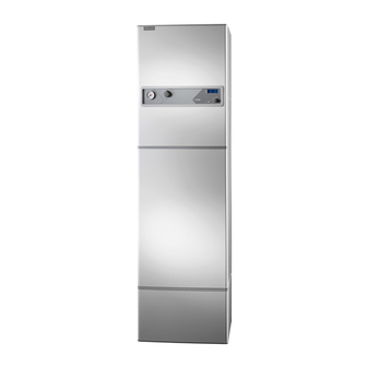
For Home Owners section in this Installation and Maintenance Instruction. FIGHTER 410P is an exhaust air heat pump with preheated supply air . This means that it collects the energy in the ventilation air and uses it for hot water and room heating. -
Page 5: System Description
For Home Owners System description Till F410P UK 1-fas Principle of operation FIGHTER 410P comprises an electric boiler with a Uteluft Tilluft Frånluft Avluft Outdoor air Supply air Exhaust air Extract air copper lined water heater and a heat pump which recovers energy from the ventilation air. -
Page 6: Front Panel
19,2 For Home Owners 70,5 Front panel 135,3 90.5 Upper (visible) part of the front panel 98,6 Pressure gauge Switch Indicator lamps Numerical display Extra hot water Offset heating curve Art.nr. 611822 FIGHTER 410P... -
Page 7: Visible Functions
Parts of the immersion heater are Art.nr. 611822 disabled by external controllers (load With the Heating curve offset button you monitor, etc). can change the offset of the heating curve Not lit Immersion heater is not operational. and thus the room temperature. FIGHTER 410P... -
Page 8: Lower (Hidden) Part Of The Front Panel
For Home Owners Front panel Lower (hidden) part of the front panel Indicator Operating Channel Heating lamps mode selection curve selection Art.nr. 611603 Miniature circuit-breaker Fan speed Temperature limiter FIGHTER 410P... -
Page 9: Hidden Functions
Art.nr. 611822 1 Boiler temperature 2 Supply temperature 3 Outside temperature 5 Extract air temperature Normally the display always shows channel 1. When you have browsed through the channels; channel 1 returns after a while. Art.nr. 611822 Art.nr. 611822 FIGHTER 410P... -
Page 10: Room Temperature Automatic Heating Control System
One line approximately rep- resents a 1 degree change in room temperature. NOTE! An increase in the room temperature may be inhibited by the radiator or floor heating thermostats, if so these must be turned up. Art.nr. 611603 FIGHTER 410P... -
Page 11: Maintenance Routines Cleaning The Air Filter
FILTER any dirt. Check that the filter is not damaged. New original filters can be ordered from NIBE. ■ Assembly takes place in the reverse order. Every third month a reminder for cleaning the filter is shown in the display as “A-01”. Note that the time will be set to zero by setting the switch to "0". -
Page 12: Checking The Safety Valves
Åter- Fram- and adjusting ledning ledning radiatorer radiatorer FIGHTER 410P has three safety valves, one for the Extract air temperature v.v. k.v. heating system and two for the water heater. Åter- Fram- ledning ledning radiatorer radiatorer The safety valves must be checked regularly. -
Page 13: General Information For The Installer
Hard water areas Unterer Grenzwert Hot water temperature "Extra hot water" Hot watertemperature "Normal" Normally it is no problem to install FIGHTER 410P in Boiler temperature hard water areas since the maxing working tempera- ture is 60 °C. The temperature of the hot water in the water heater Maximum boiler and radiator may vary between about 50 and 65 °C. -
Page 14: Pipe Connections General
70 litres in the boiler section. or bends in the pipework. See following picture. The pressure vessel in the FIGHTER 410P is approved for max 9.0 bar (0.9 MPa) in the water heater and 2.5 bar (0.25 MPa) in the double shell section. -
Page 15: Tap Water Connection
Warning to the Heat pump Water heater installer! FIGHTER 410P COMPACT This installation is subject to building regulation approval, notify the Local Authority of intention to install. Warning to the... -
Page 16: Supply Air Battery
The delivered output in the diagram is calculated when dimension- ing the heating system 55/45 °C respective 35/25 °C (floor heat- ing). åb Wasser- Abgegebene 55/45 fluss Heizleistung ganz geöffnet Risiko für niedrige Zulufttemperatur 35/25 FIGHTER 410P... -
Page 17: Ventilation Connection
For Home Owners Ventilation connection Ventilation flow FIGHTER 410P is connected so that all ventilation air The choice of position and with that the fan speed is made according to the following criteria: except the kitchen fan passes the evaporator (62) in the heat pump. -
Page 18: Duct Installation
A duct in a masonry chimney stack vent leakage. must not be used for extract air. The air duct system should, at a minimum, be of air tightness class B and in general designed according to applicable building standards. FIGHTER 410P... -
Page 19: Electrical Connections
Immersion heater NOTE! The electrical installation, wiring and FIGHTER 410P is delivered with a 8 kW immersion any service work must be done in strict heater (1). It is started and stopped via the microproes- sor card (34). If a failure occurs there is a temperature... -
Page 20: Setting The Fan Capacity
(connec- compressor is operational (except in defrosting mode). tion on delivery) In addition, the flow temperature is limited to maxi- mum 60 °C. Pins 2 and 3 are strapped Limited immersion heater operation FIGHTER 410P... -
Page 21: Connecting The Outside Sensor
A + B both (both make or both break). The contacts must be (Brown, white and black group) connected in parallel for make contact function and in series for break contact function. * Only with 13.5 kW immersion heater output FIGHTER 410P... -
Page 22: Commissioning And Adjusting
“A”). ■ Set the design capacity (35) on the circulation pump’s switch (16). See the section Pipe connec- tions - Pump and pressure drop diagram. Make sure that the switch is not in an intermediate posi- tion. FIGHTER 410P... -
Page 23: Setting The Ventilation
Open safety valve (52) to let air into the system. mal, normal temperature during minimum one hour. After that the systems shall be flushed out and re-filled again. FIGHTER 410P... -
Page 24: Setting The Automatic Heating Control System
For the Installer Setting the automatic heating control system Heating curve offset -2 Setting with diagrams FIGHTER 410P is equipped with outdoor temperature HEATING CURVE HEATING CURVE VÄRMEKURVA controlled automatic controls. This means the supply °C °C temperature is regulated in relation to the current out-... -
Page 25: Service
Set point. Shows the set room temperature. Shows – – when the room sensor is not con- nected. Room sensor Actual value. Shows the true room temperature. Shows – – when the room sensor is not con- nected. 17– 21 No function FIGHTER 410P... -
Page 26: Dealing With Malfunctions
■ Wrong operating mode selected with button (25). If the operating disturbance cannot be rectified by means of the above an installation engineer should be called. If necessary set the Switch to “ ” (manual shunt operation necessary). FIGHTER 410P... -
Page 27: Resetting The Miniature Circuit Breakers
This fault state must not be repeatedly fault code must be cleared from the display by switch- reset, this will bring about a risk for ing the heat pump off and on again. freezing of the supply air battery. FIGHTER 410P... -
Page 28: Resetting Pressostats
It is usually easier to start the circulation pump with High pressure pressostat FIGHTER 410P running, switch (8) set to “1”. If help- (33) ing the circulation pump to start is performed with FIGHTER 410P running, be prepared for the screw- driver to jerk when the pump starts. -
Page 29: Electrical Circuit Diagram
0 kW Vit white 6,0 kW Brun brown Re 8 Läge R Power supply for Matning för load monitor effektvakt (tillbehör) (accessories) N N 3 Contactor marking Kontaktormärkning For all conntactors Gäller samtliga kontaktorer – 230 V 12 V FIGHTER 410P... -
Page 30: Dimensions
Measuring principle Erforderlicher Platz zur Demontage der oberen Frontluke Geringster Wand- abstand 10 mm Compression ring Copper pipe Klämring Cu-rör Zuluft Ø 125 Abluft Ø 125 Außenluft Ø 125 Fortluft Ø 125 Klemmring Kupferrohr FIGHTER 410P Schutzkleinspannung Ø 16... -
Page 31: Component Positions
For the Installer Component positions FILTER FILTER 31 32 55 56 v.v. 149 151 73 152 148 150 70 103 k.v. Radiator Åter- Radiator Fram- ledning ledning system inlet system outlet radiatorer radiatorer FIGHTER 410P... -
Page 32: Component Positions
Height: 125 mm 385 till 535 245 alt. 345 Part no 089 195 Filling hose Room sensor RG 10 In some cases a room sensor can be used as a supplement to the ordinary automatic con- trol system. FIGHTER 410P... -
Page 33: List Of Components
108 Tundish from safety valve 150 Connection for flexible hose to heating-side 109 Tundish from temperature relief valve 151 Filling valve, heating system (CW-side) 115 Terminal block 152 Filling valve, heating system (heating-side) 145 Temperature and pressure valve 169 Temperature limiter, compressor FIGHTER 410P... -
Page 34: Technical Specifications
Total Power input 0,715 kW Current 3,6 A Rating condition: Exhaust air: 150 m 3 /h Air flow Inlet dry bulb temperature 20 °C Inlet wet bulb temperature 12 °C Water: Inlet temperature 40 °C Outlet temperature 45 °C FIGHTER 410P... - Page 36 NIBE CZ, V Zavetri 1478/6, CZ-170 00 Prague 7 Tel: +420 266 791 796 Fax: +420 266 791 796 E-mail: centrala@nibe.cz www.nibe.cz NIBE Systemtechnik GmbH, Am Reiherpfahl 3, 29223 Celle Tel: 05141/7546-0 Fax: 05141/7546-99 E-mail: info@nibe.de www.nibe.de Vølund Varmeteknik, Filial af NIBE AB, Brogårdsvej 7, 6920 Videbæk Tel: 97 17 20 33 Fax: 97 17 29 33 E-mail: info@volundvt.dk www.volundvt.dk...
Need help?
Do you have a question about the FIGHTER 410P and is the answer not in the manual?
Questions and answers