
Subscribe to Our Youtube Channel
Related Manuals for Nibe FIGHTER 2010 Series


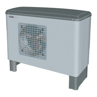
Summary of Contents for Nibe FIGHTER 2010 Series
- Page 1 INSTALLATION AND MAINTENANCE INSTRUCTIONS FIGHTER 2010 MOS GB 0609-5 611864 FIGHTER 2010 L E K...
-
Page 3: Table Of Contents
Contents For Home Owners General Maintenance routines Concise product description ........ 2 Maintenance of FIGHTER 2010 ......4 Setting table ............2 System description Principle of operation .......... 3 For the Installer General information for the installer Commissioning and adjusting Transport and storage .......... -
Page 4: General
FIGHTER 2010 is a Swedish made quality product offering a long life span and safe operation. To be filled in when the heat pump has been installed. The serial number (103) should always be stated in all correspondence with NIBE. 089_ _ _ _ _ _ _ _ _ _ _ Installation date Type designation... -
Page 5: System Description
For Home Owners System description Principle of operation FIGHTER 2010 is an outdoor air heat pump, specially of a water heater and additional heat in the form of an designed for the Nordic climate. FIGHTER 2010 utilis- electric boiler. FIGHTER 2010 and VVM 240 together es the outside air so there is no need for bore holes or make up a complete heating plant. -
Page 6: Maintenance Routines Maintenance Of Fighter 2010
For Home Owners Maintenance routines Maintenance of FIGHTER 2010 FIGHTER 2010 is equipped with control and monitor- If necessary the outer casing can be cleaned using a ing equipment, however some exterior maintenance is damp cloth. Care must be exercised so that the plastic still necessary. -
Page 7: General Information For The Installer
For the Installer General information for the installer Transport and storage Control FIGHTER 2010 should be transported and stored ver- FIGHTER 2010 is equipped with an internal electronic tically. controller that handles all functions necessary for heat pump operations. Inspection of the installation Accordingly, defrosting, stop at max/min temperature, connection of the compressor heater as well as Current regulations require the heating installation to... -
Page 8: Pipe Connections
“Docking” or according to one of the system solutions that can be downloaded from the website www.nibe.se/vvs . The heat pump must be vented by the upper connec- tion (70, WW-out) using the venting nipple on the enclosed flexible hose. -
Page 9: Pressure Drop, Heating Medium Side
For the Installer Pipe connections Pressure drop, heating medium side FIGHTER 2010-6 FIGHTER 2010-6 Pressure drop Tryckfall Flow Flöde 0,05 0,15 0,25 0,35 0,45 FIGHTER 2010-8 FIGHTER 2005-8, 10 FIGHTER 2010-8 Pressure drop Tryckfall Flow Flöde 0,05 0,15 0,25 0,35 0,45 FIGHTER 2010... -
Page 10: Docking General
15–20 accordance with current regulations for all docking litres boiler water per kW output on the heat pump is options. See www.nibe.se/vvs for more docking recommended. options. FIGHTER 2010 docked to the oil-fired/pellet boiler together with... -
Page 11: Several Fighter 2010S Docked With Smo 10
For the Installer Docking Several FIGHTER 2010s together with SMO 10 and water heater (floating condensing) SMO 10 SÄV HP 2 SÄV SÄV HP 1 VXV1 SMO 10 controls up to nine FIGHTER 2010s (of which heating is shunted in from the oil-fired boiler. When max one for hot water), electric element, circulation additional heat is engaged, hot water is heated using pump, shunt, etc. -
Page 12: Fighter 2010 Docked With Vvm 240
For the Installer Docking FIGHTER 2010 docked with VVM 240 (floating condensing) SÄK FIGHTER 2010 VVM 240 FIGHTER 2010 6 and 8 can be connected to VVM If FIGHTER 2010 cannot meet the heating require- 240. FIGHTER 2010 is controlled by VVM 240. ment, additional heating is shunted in from VVM 240. -
Page 13: Fighter 2010 Docked With Evc 13
For the Installer Docking FIGHTER 2010 docked with EVC 13 (floating condensing) RT 10 EVC 13 FIGHTER 2010 SÄV FIGHTER 2010 is controlled by a room thermostat and through FIGHTER 2010 during the set stop temperature. works with floating condensing against the return from the Hot water production only takes place using the existing heating system. -
Page 14: Fighter 2010 Docked To An Electric/Oil Boiler
For the Installer Docking FIGHTER 2010 docked to an electric/oil boiler (floating condensing) RT 10 Accessory or Extern alt existing control befintlig regler- equipment utrustning. SÄV FIGHTER 2010 FIGHTER 2010 is controlled by a room thermostat and Additional heat can be blocked above the set balance tem- works with floating condensing on the return from the heat- perature by means of the automatic control system in ing system. -
Page 15: Electrical Connections
For the Installer Electrical connection Electrical installation The routing of cables for heavy current and signals should be made out through the cable glands on the NOTE! heat pump's left-hand side, seen from the front. The terminal block (9) for the incoming supply is Electrical installation and service must accessed by removing the 6 screws on the plastic cover and the 3 screws (TORX 20) on the electrical box. -
Page 16: Circulation Pump
For the Installer Electrical connection Circulation pump NOTE! The following pages about When the circulation pump is connected to terminal block (11) the pump is controlled by FIGHTER thermostats, additional heat, common 2010. Pump activity is dependent on the status of alarms and downtime, do not apply FIGHTER 2010, heating/hot water requirement and when FIGHTER 2010 is controlled by... -
Page 17: Single Step Thermostat Heating (Auto Mode)
For the Installer Electrical connection Single step thermostat heating Double step thermostat (auto mode) heating You can use a basic thermostat to switch the com- pressor on and off. This thermostat should be of the A double step thermostat can also be used to switch breaking type (NC) when the set temperature has the compressor on and off. -
Page 18: Additional Heating/Downtime
For the Installer Electrical connection Additional heating/downtime Example of additional heating connection FIGHTER 2010 is equipped with a potential free con- tactor intended for additional heat: Max 250V, 2A. Basic circuit diagram for connection of auxiliary relays The setting of the outdoor air temperature (balance for additional heating and downtime. -
Page 19: Commissioning And Adjusting
For the Installer Commissioning and adjusting Stop temperature Preparations When using a standard radiator system and with hot Before commissioning check that the heating circuit is water heating the stop temperature should not fall filled and well vented. Check the pipe system for below -7 °C. -
Page 20: Starting And Checking
For the Installer Commissioning and adjusting Start-up and inspection Adjustment, charge flow ■ Modular cable (44) or thermostat/strap, terminal Adjusting the temperature difference (∆T) between the (30) is disconnected. flow temperature and the return temperature. ■ The working switch is turned on. This is easily done by using the temperatures mea- ■... -
Page 21: Control Explanation
For the Installer Control Explanation Heater The fan has two speeds, high and low. The fan follows The compressor heater is always active when the com- the compressor’s different power stages. Low fan pressor is switched off. speed, the compressor’s lower output is connected. The drip tray heater is connected when the outdoor tem- High fan speed, the compressor’s higher output is perature drops below the set value and is disconnected... -
Page 22: Channel Description
For the Installer Control Channel description You can browse back and forth through the display’s 09 Longest permitted defrosting time. Adjustable be- tween 5 and 12 minutes. Factory setting 7 min- channels using the Plus and Minus buttons. utes. To modify a value, first press the Enter button to acti- vate modification mode. - Page 23 For the Installer Control Channel description 20 Control inputs/address options. 21 Alarm input status (HP, LP and MS), 1 indicates the input is OK. If position (0), auto mode is selected on chan- nel 13 1 / 1 / 1 1 / 1 High pressure pressostat Motor protection...
-
Page 24: Sensors Sensor Placement
For the Installer Sensors Sensor placement 15 Outdoor air sensor 21 Current sensor 33 Low pressure pressostat 41 High pressure pressostat 86 Temperature sensor, evaporator 88 Temperature sensor, fluid pipe 89 Temperature sensor, supply line 90 Temperature sensor, suction gas 91 Temperature sensor, hot gas 93 Temperature sensor, return Data for hot gas sensor... -
Page 25: Electrical Circuit Diagram
For the Installer Electrical circuit diagram T5AH Common alarm L2 L3 C S R PE 2 PE 3 * RSB 4015-B input A2, RSE 4012-B (MSR 10) input A3-L3. ** Circulation pump for heat medium controlled from FIGHTER 2010, not included with the delivery. FIGHTER 2010... -
Page 26: Component Positions Component Positions
-Volym: 3 bar (0.3 MPa) -Beräkningst ryck: 3,9 bar (0,39 MPa) -Provtryck: -Beräkningst emp: 100 °C Köldmediem ängd: 2,2 kg Köldtyp: R407C 26 bar (2,6 MPa) Provtryck, kylsystem: SE-285 21 Markaryd, SWEDEN Made by NIBE AB, Concealed! Dold! FIGHTER 2010... -
Page 27: List Of Components
For the Installer List of components Miniature circuit breaker High pressure pressostat Service connection, low pressure Service connection, high pressure Terminal block, incoming supply Display contrast Terminal block, circulation pump, common Terminal block, communications (a/b) alarm Expansion valve Terminal block, internal Operating condenser, fan Terminal block (additional heating) Particle filter (supplied) -
Page 28: Sound Pressure Levels
For the Installer Sound pressure levels Sound pressure levels FIGHTER 2010 is usually placed next to a house wall, which gives a directed sound distribution that should be considered. Accordingly, you should always at- tempt to find a placement on the side that faces the least sound sensitive neighbouring area. -
Page 29: Dimensions
For the Installer Dimensions Dimensions and setting-out coordinates 1074 1186 There should be a minimum of 350 mm clearance behind the heat pump for servic- ing. An area of 1,000 mm is required in front of the heat pump for ser- vice work. -
Page 30: Technical Specifications
For the Installer Technical specifications IP 24 FIGHTER 2010 -6 FIGHTER 2010 -8 Input/Output* at 2/35 °C ** (kW) 6.6/1.9 8./2.3 Input/Output* at 7/35 °C ** (kW) 7.2/1.9 9.9/2.4 Input/Output* at -7/45 °C ** (kW) 4.1/1.8 4.7/2.0 Input/Output* at 0/45 °C ** (kW) 5.4/2.0 6.6/2.3... -
Page 31: Enclosed Kit
For the Installer Enclosed kit Particle filter R25 Part no. 024 076 L E K 2 flexible hoses (R25) with 4 seals 4 adjustable feet with holders Part no. 424 088 Heating pipe paste 4 cable ties Aluminium tape Part no. 025 179 Part no. -
Page 32: Accessories Accessories
Miscellaneous Accessories SMO 10 Control box Part no. 089 259 RT 10 Room thermostat Part no. 418 366 VVM 240 Hot water module Part no. 089 263 (recommended for FIGHTER 2010-6 and -8) FIGHTER 2010... -
Page 33: Dealing With Malfunctions Fighter 2010 Not In Operation
NOTE! The product’s serial number should always be stated in all correspondence with NIBE. 089_ _ _ _ _ _ _ _ _ _ _ If the operating disturbance cannot be rectified by means of the above an installation engineer should be called. -
Page 34: Miscellaneous
Miscellaneous FIGHTER 2010... - Page 36 Fax: 22 90 66 09 Jerikoveien 20 E-mail: info@nibe.se 1067 Oslo www.nibe-villavarme.no Tel: 085 662 84 90 NIBE-BIAWAR Sp. z o. o. Fax: 085 662 84 14 Aleja Jana Pawła II 57 E-mail: sekretariat@biawar.com.pl 15-703 BIAŁYSTOK www.biawar.com.pl Tel: +46 - (0)433 - 73 000...
Need help?
Do you have a question about the FIGHTER 2010 Series and is the answer not in the manual?
Questions and answers