
Related Manuals for Nibe FIGHTER 1310


Summary of Contents for Nibe FIGHTER 1310
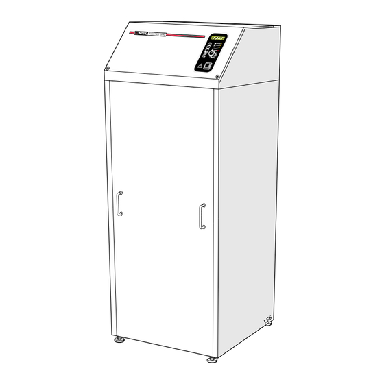
- Page 1 INSTALLATION AND MAINTENANCE INSTRUCTIONS FIGHTER 1310 MOS GB 0349-1 611854 FIGHTER 1310...
-
Page 3: Table Of Contents
Connecting temperature sensors supplied Dimensions and setting-out coordinates ....44 with the unit ..............28 Accessories Connecting more than one FIGHTER 1310 ....28 Accessories ..............45 Temperature drop ............28 Technical specifications Terminal blocks for external units ......29 Technical specifications .......... -
Page 4: General
Completedby the installer when the heat pump is installed Installation date Type designation / serial number FIGHTER 1310- _ _ kW / 689 _ _ _ _ _ _ _ _ _ _ _ Accessories: Room control ....Hot water control .... -
Page 5: System Description
For Home Owners System description Principle of operation FIGHTER 1310 consists of two heat pump modules Ground water can also be used as a heat source. This and a control computer with a display to control the requires an intermediate heat exchanger. -
Page 6: Front Panel
WW-out 49(50)°C VB-Fram 49 (50) °C Hot-Water 51 °C 51°C Varmvatten Function keys Indicator lamps Increase/reduce heat Switch NOTE! Make sure there is water in the heat pump before turning the switch (A) into position 1 or R. FIGHTER 1310... -
Page 7: Functions
LED flashes slowly. Lit during hot water charging. Room heating: Not lit The next time Extra hot water is pressed you return to Hot water: Lit during hot water charging normal mode. Additional heat Not lit * Only possible with an external immersion heater. FIGHTER 1310... -
Page 8: General
If the required room temperature is not obtained, read- by a control computer. Before the computer can do justment may be necessary. this, some basic settings are required. FIGHTER 1310 also offers the possibility to control two different tem- perature curves. -
Page 9: Basic Values
VPA, the After adjustment the correct amount of heat for the FIGHTER 1310 can be used for hot water production. current outdoor temperature is supplied. The heat In those cases connection to the water heater has... -
Page 10: Information Available On The Display
For Home Owners Control, normal Available information and on-display settings FIGHTER 1310 has a two-line LCD display. The heat pump can be set via this display and its associated buttons. Outdoor -14 °C Channel selection Boiler 25 °C The Channel button lets you browse through... - Page 11 Setting range: -12 - +10 °C. * Displayed only if more than one heat pump is installed (i.e. if the chosen value for HP-no. in menu 18 is greater than > 0). ** Only displayed if a room sensor is connected. FIGHTER 1310...
- Page 12 HP off, HP on, HP start in X minutes or High return temp for module A or B respectively. NOTE! Enter the chosen settings in the table on page 2 of this manual. The details are important for service work. FIGHTER 1310...
-
Page 13: Information Available On The Display
For Home Owners Control, double curves Available information and on-display settings FIGHTER 1310 has a two-line LCD display. The heat pump can be set via this display and its associated buttons. WW-out 47(52) °C Channel selection Hot-water 48 °C The Channel button lets you browse through... - Page 14 Setting range: -12 - +10 °C. * Displayed only if more than one heat pump is installed (i.e. if the chosen value for HP-no. in menu 18 is > 0). ** Only displayed if a room sensor (RG20) is connect- FIGHTER 1310...
- Page 15 20 °C, max 40 °C. With fixed condensation, the same setting is cho- sen for the minimum and maximum levels. (Sen- sor location, temperature setting and pump flow are taken into account.) FIGHTER 1310...
-
Page 16: General Information For The Installation Engineer
Installation Inspection of the installation The FIGHTER 1310 must be installed on a firm sur- Current regulations require the heating installation to face, preferably a concrete floor or a concrete founda- be inspected before it is commissioned. The inspec- tion in a boiler room or a separate equipment room. -
Page 17: General
B is allowed to start. Basic setting: 200. Setting range: 61 – 250. If there is more than one heat pump connect- ed together, (i.e. if HP-no. is greater than 0), the basic setting is taken from a table in menu FIGHTER 1310... - Page 18 [P] Stop temperature for water heater charging when operating with additional heat only. Basic setting: 50. Setting range: 10 – 70. * Only shown if a boiler sensor is connected. ** This menu is a submenu to 12a if a boiler sensor is connected. FIGHTER 1310...
- Page 19 Cal.Out 0 Room 0 Returns to normal setting eight minutes after the BrinIn 0 BrinO 0 last button was pressed. Cal. Out Parallel [P] Calibration of outside sensors. Setting of Increase/Reduce heat potentiometer to displace heating curve (parallel offset). FIGHTER 1310...
- Page 20 Shunt HW-val HP-no Shunt 0 or 1 [P] Sequence number of FIGHTER 1310 when Shunt = 0, control, normal and additional with more than one unit is connected together; see electric boiler or oil-fired boiler. table. HP-no. is set to 0 if only one heat pump is Shunt = 1, control, double curves installed.
-
Page 21: Drying The Concrete Base
It is important with some concrete floors to maintain the right floor temperature during an initial period. This is so the floor dries correctly. FDP-int1 FIGHTER 1310 has a function for this drying process. WW-out 25 °C The process can be divided into two periods where... -
Page 22: Pipe Connections
50 °C and an outgoing temperature from the heat pump of Heating about 60 °C. Since FIGHTER 1310 is not fitted with waterpump B shutoff valves, these must be fitted outside of the heat HW return pump to facilitate servicing. -
Page 23: Pressure Expansion Vessel
0.5 bar and the safety valve’s opening Brine pressure 3 bar. volume 100 200 500 600 700 800 900 1000 Pump capacity diagrams, heating water side Available pressure equipment Pressure FIGHTER 1310-25/30 Pressure FIGHTER 1310-20 100 10 100 10 Flow Flow 1000 1500 2000... -
Page 24: Docking
SÄV KB-f Shutoff valve Mixing valve Check valve FIGHTER 1310 gives priority to hot water charging at KB-f Brine in VVB Water heater half power (heat pump module B) via a reversing KB-r Brine out valve (VXV). When the water heater/accumulator tank... -
Page 25: Option 2 Fighter 1310 Docked With Electric Boiler And Water Heater
VVB / ACK KB-r SÄV KB-f Shutoff valve FIGHTER 1310 gives priority to hot water charging at Check valve half power (heat pump module B) via a reversing valve (VXV). When the water heater/accumulator tank Water heater (VVB/ACK) is fully charged the reversing valve (VXV) Particle filter switches over to the heating circuit. -
Page 26: Option 3 Two Or More Fighter 1310S Docked With Boiler And Water Heater
VVB / ACK VVB / ACK SÄV SÄV Shutoff valve FIGHTER 1310 is designed so that several units can Check valve be interconnected to satisfy large output require- ments. Water heater Module A (VP1) starts first when there is a heating Particle filter requirement. -
Page 27: Option 4 Control, Double Curves
FG2 is controlled against curve 2 with the help of the mixing valve SV. Flow sensor 1 FIGHTER 1310 gives priority to hot water charging at Flow sensor 2 half power (heat pump module B) via a reversing Hot water sensor valve (VXV). -
Page 28: Electrical Connections
Where there is more than one heat pump, each unit must have a separate supply. The FIGHTER 1310 does not include an isolator switch on the incoming electrical supply. This Check the direction of rotation of the brine pump (35) (clockwise as seen from the front cover). -
Page 29: External Control Of The Electrical Supplement And Compressor
For the Installation engineer Electrical connection External control of the electrical supplement and compressor When FIGHTER 1310 controls an external electri- Terminals 2 and 3 should be connected together to cal supplement disconnection of the entire electri- block the compressor as well as the supplement. -
Page 30: Connecting Temperature Sensors Supplied With The Unit
Connecting more than one FIGHTER 1310 When more than one FIGHTER 1310 is used, each WW-in unit must receive signals from flow, return and outside PG/FG 2 temperature sensors. -
Page 31: Terminal Blocks For External Units
Terminal (19) terminal block (6) is made with an alarm. Standby mode Control voltage 230 V, to start e.g. additional heat and pumps, is controlled from the switch (8). FIGHTER 1310 Example, connection: Auxiliary relays to actuate external supplement and/or circulation pump. Extra hot water Control voltage 230 V, is connected to the auxiliary relay for extra hot water. -
Page 32: Control With Oil Supplement Option 1 Connection
Boiler Panna Extra hot water Extra varmvatten RG FG UG FIGHTER 1310 1 2 3 4 5 6 7 8 9 10 1112 13 14 15 1617 18 19 20 Reversing valve, VST 11 Boiler sensor Hot water sensor Return sensor... -
Page 33: Menu 19
Additional heat select in menu 14 is set to 1. The relay contact should be equipped with a bypass to be able to use additional heat, oil in standby mode. 230 V Loop Byglas TS3 ut TS3 in TS1/SH- TS2/SH+ Re 4 Re 5 Re 2 FIGHTER 1310... -
Page 34: Connection
Elpanna Extra hot water Extra varmvatten VVG RG FG FIGHTER 1310 1 2 3 4 5 6 7 8 9 10 1112 13 14 15 1617 18 19 20 Reversing valve, VST 11 Hot water sensor Return sensor Flow sensor... -
Page 35: Menu 19
Electricity: Additional heat can be controlled from Shunt FIGHTER 1310 in 1, 2, 3 or 7 steps. Control is either binary or linear and utilises 1, 2, or 3 relays in FIGHTER 1310. Shunt should be set to 0 for this system. -
Page 36: Control With Two Or More F 1310S Option
Control with two or more Fighter 1310s option 3 Connection TSF 10 Kanal 4 In VP4 alt en andra TSF 10 Värmebärare retur Kanal 3 In Värmebärare fram FIGHTER 1310 VP3 Kanal 2 In Reservingång Kanal 1 In Utetemperatur Boiler Panna Extra hot water... -
Page 37: Menu 19
For the Installation engineer Control with two or more Fighter 1310s option 3 Menu 19 Shunt Shunt should be set to 0 for this system. FIGHTER 1310... -
Page 38: Control, Double Curves Option 4 Connection
Elkassett/ boiler elpanna RG FG UG Extra hot water Extra varmvatten FIGHTER 1310 1 2 3 4 5 6 7 8 9 10 1112 13 14 15 1617 18 19 20 Shuttle valve Hot water sensor Return sensor Flow sensor... -
Page 39: Menu 19
20, should be connected to terminals 1 and 5 on ter- minal block 30. The preset value is 8, this can be changed on menu 2b. If the room thermostat, RT 20 is connected a room sensor cannot be connected. FIGHTER 1310... -
Page 40: Commissioning And Adjusting
Fill in the commissioning report on page 2. to be 2 –5 °C when the system is in balance, with both compressors running. A high difference indi- Set the control computer to suit the needs of the cates a high brine flow. building. FIGHTER 1310... -
Page 41: Internal Venting Valves
Selector switch for compressors A and B The normal position is 1. Alarm lamp, motor protection device (compressor) An alarm lamp indicates that the motor protec- tion device has tripped. In the event of a fault set the switch (25) to 0. FIGHTER 1310... -
Page 42: Setting The Automatic Heating Control System Setting With Diagrams
For the Installation engineer Setting the heating controls Setting using diagrams Heating curve offset -2 The heating control system of the FIGHTER 1310 is HEATING CURVE KURVLUTNING controlled by the outside temperature. This means the °C flow temperature is regulated in relation to the current 15 14 13 12 outdoor temperature. -
Page 43: Circuit Diagram
For the Installation engineer Circuit diagram N PE X13b X13b X13b X13b T5AH X13b X13b Reserv- läge Larm Olja TS1/S4- Ts2/S4+ Ventil X136,6 FIGHTER 1310... -
Page 44: Component Positions Component Positions
For the Installation engineer Component placement 37 26a FIGHTER 1310... -
Page 45: List Of Components
33 a, b High pressure pressostat Type plate Computer with display, including sensor Type plate, cooling section Brine pump 97 a,b Starting current limiter 36 a, b Indicator lamp, motor protection device, compressor Motor protection device, brine pump Contactor, brine pump FIGHTER 1310... -
Page 46: Dimensions
Kabelintag, Cable gland, sensors givare An area of 800 mm is required in front of the heat pump for service work. Cable gland, incoming Kabelintag, starkström (matning) supply FIGHTER 1310... -
Page 47: Accessories
Reversing valve, Cu-pipe Ø28 (Max recommended charge power, 15 kW) Temperature Immersion heater IU signal distributor (3 kW, 6 kW and 9 kW) TSF 10 Use 2-4 FIGHTER 1310 Art-No: 3 kW 018084 6 kW 018088 9 kW 018090 Art-No: 018823... -
Page 48: Technical Specifications
Art-No 021081 Art-No 025910 Temperature sensors with probes Art-No 418027 Tubes for sensors Art-No 008392 Particle filter Art-No. 024076 (R25) Hoses with seals 024077 (R32) (heating water flow, R25 Aluminium tape 024194 (R40) male/female) Art-No 025179 Art-No. 424088 FIGHTER 1310... -
Page 49: Low Room Temperature
NOTE! High room temperature As FIGHTER 1310 can be connected Cause: Incorrect setting of the Curve slope and/or Increase/reduce heat. to a large number of external units Action: Adjust the setting. -
Page 50: Draining, Heat Water System
Start FIGHTER 1310 and check whether the circu- lation pump runs. It is usually easier to start the circulation pump with FIGHTER 1310 running, switch (8) set to 1. If helping the circulation pump to start is performed with FIGHTER 1310 running, be prepared for the screw- driver to jerk when the pump starts. - Page 52 NIBE AB Box 14 Tel: +46 - (0)433 - 73 000 Järnvägsgatan 40 Fax: +46 - (0)433 - 73 190 SWEDEN SE-285 21 MARKARYD www.nibe.com...
Need help?
Do you have a question about the FIGHTER 1310 and is the answer not in the manual?
Questions and answers