
Related Manuals for Nibe FIGHTER 1110


Summary of Contents for Nibe FIGHTER 1110
- Page 1 INSTALLATION AND MAINTENANCE INSTRUCTIONS FIGHTER 1110 MOS GB 0427-1 611690 3 x 400V FIGHTER 1110...
-
Page 3: Table Of Contents
Indications ............37 Connecting the supplied temperature Draining, heat medium side ........ 38 sensor with fixed condensing ......22 Draining, collector side ........38 Connection of heating medium pump, Help starting the circulation pump ......38 fixed condensing ..........22 FIGHTER 1110... -
Page 4: Concise Product Description
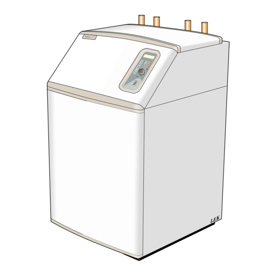
FIGHTER 1110 you should read through the For Home Owners section in this Installation and Maintenance Instruction. FIGHTER 1110 is a base heat pump for heating small hous- es, apartment blocks and industrial premises. The ground, rock or lakes can be used as the heat source. -
Page 5: System Description
For Home Owners System description Principle of operation FIGHTER 1110 consists of a heat pump module and a containing water mixed with antifreeze. control computer with a display for operating the heat Ground water can also be used as a heat source. This pump and a soft-start relay (5-15 kW) and additional requires an intermediate heat exchanger. -
Page 6: Front Panel
Front panel Front panel WW-out 49 (50) °C Display Hot-water 51 °C Function keys Indicator lamps Increase/ reduce heat Switch NOTE! Make sure there is water in the heat pump before turning the switch (A) into position 1 or FIGHTER 1110... -
Page 7: Functions
The next time the Extra hot water button is pressed, No room heating mode (only hot water): Press the the system returns to normal mode. Operating mode button again. LEDs: Room heating: Not lit Hot water: Lit during hot water charging Additional heat Not lit FIGHTER 1110... -
Page 8: Controls General
The colder it is outside, the warmer radia- clockwise or anticlockwise. One line approximately tors and floor heating system must be. With the FIGHTER 1110, this adjustment is done automatically represents a 1 degree change in room temperature. by a control computer. Before the computer can do NOTE! An increase in the room temperature may be this, some basic settings are required. -
Page 9: Heat Production
If the FIGHTER 1110 is fitted with the Electrical sup- The larger the subnormal temperature, the greater the plement accessory the unit can be used solely as an heat production. -
Page 10: Information Available On The Display
For Home Owners Control Available information and on-display settings FIGHTER 1110 has a two-line LCD display. The heat pump can be set via this display and its associated buttons. WW-in 37(53) °C Channel selection HW start 49(44) °C The Channel button lets you browse through... -
Page 11: Curveslope
Channel calculated temperature, values above and below the set button. You then return to display 1. value can temporarily occur. For example, the suitable values for floor heating with floating condensing could be min 18°C, max 40°C. FIGHTER 1110... -
Page 12: General Information For The Installer
200 – 300 m 70 – 90 m 250 – 400 m 90 – 110 m FIGHTER 1110 is placed on a firm base, preferably a concrete floor or foundation. FIGHTER 1110 should 325 – 2 x 250 m 120 – 140 m be setup with its rear against an outer wall in a 400 –... -
Page 13: Control (Also With Accessories)
[P] Degree minute deficit before the heat pump can start. Basic setting: 60. Setting range: 5 – 250. Add-°min [P]Additional degree-minute deficit before the first stage of additional heat (SH) is allowed to be switched on. Basic setting: 300. Setting range: 50 – 2500. FIGHTER 1110... -
Page 14: Hp-Int
Brine In[P] Calibration of brine fluid flow sensor. Setting range: 1 – 50 %. Brine Out [P] Calibration of the brine fluid return sensor. Setting values for all quantities: -5 – +5. * Only shown if a boiler sensor is connected. FIGHTER 1110... -
Page 15: Parallel
This is so the floor dries correctly. FIGHTER 1110 has a function for this drying process. The process can be divided into two periods where the number of days and temperature are set for Man:Manual test of outputs. -
Page 16: Pipe Connections
To avoid condensation, all pipes and other cold sur- and an outgoing temperature from the heat pump of faces must be isolated with diffusion-proof material. about 60 °C. Since FIGHTER 1110 is not fitted with shutoff valves, these must be fitted outside of the heat Extract air Exhaust air pump to facilitate servicing. -
Page 17: Pump Capacity Diagrams, Heating Medium Side
For the Installer Pipe connections Pump capacity diagrams, heating medium side Available pressure setup Pressure drop Pressure drop Tryckfall Tryckfall FIGHTER 1110 4 kW FIGHTER 1110 5 kW FIGHTER 1115 4 FIGHTER 1115 5 Flow Flow Flöde Flöde 250 500 750... -
Page 18: Docking
ETS 11 etc. are ordered separately. The safety equip- ment must be installed in accordance with current reg- ulations for all docking options. Option 1 – FIGHTER 1110 docked with immersion heater and hot water heater (floating condensing) SÄV El VVB SÄV... -
Page 19: Option 2 - As Option 1 With Room Sensor Only
BK / JK FIGHTER 1110 prioritises heating of hot water via a immersion heater (ELK) is connected automatically reversing valve (VXV). When the water heater/accumu- when the energy requirement exceeds the capacity of lator tank (VVB/ACK) is fully charged the reversing valve the heat pump. -
Page 20: Option 4 - Double Shelled Boiler
For the Installer Docking Option 4 – FIGHTER 1110 docked to double-shelled electric boiler/exhaust air heat pump (floating condensing) SÄV Cirk.pump Värmepump Varmvatten Tillsatsvärme Larm Kontrollera att vatten finns i pan- nan innan den in- kopplas. BK / JK The ground heat pump only heats the heating circuit. -
Page 21: Option 6 - Firewood Boiler
For the Installer Docking Option 6 FIGHTER 1110 docked to an wood-fired boiler (fixed condensing) SÄV Extern alt External or befintlig regler- existing control utrustning. equipment SÄV Cirk.pump Värmepump Varmvatten Tillsatsvärme Larm Kontrollera att vatten finns i pan- nan innan den in- kopplas. -
Page 22: Electrical Connections
Electrical installation and wiring must Cable duct Cable duct be carried out in accordance with the for the supply. for sensors. stipulations in force. Terminal block, incoming electricity (9) FIGHTER 1110... -
Page 23: Connection
If an automatic fuse unit is used this should have a motor characteristic D (compressor operation). For MCB size see Technical Specifications. NOTE! The FIGHTER 1110 does not include an isolator switch on the incoming electrical supply. Therefore A 1-phase connection without the installation must be preceded by a circuit- electrical supplement requires pos L1 breaker. -
Page 24: Connecting The Supplied Temperature Sensor With Floating Condensing
9 on terminal (13) and is then connected in parallel to the heat transfer fluid pump (35). This refers to docking options 5 and 6, see the Docking section. The figure shows FIGHTER 1110, 5 — 15 with electrical supplement ETS 11. FIGHTER 1110... -
Page 25: Commissioning And Adjusting Preparations
Fill the level vessel with liquid up to SF Particle filter NK Level vessel around 75%. Now shut the filling plug and open the valve under the vessel. Reset normal mode by setting Add to 0. FIGHTER 1110... -
Page 26: Filling The Heating/Heating Medium Systems
10°C when the heat pump heats the hot water without additional heat. A high difference could depend on a low heat medium flow. Fill in the commissioning report on page 2. Set the control computer to suit the needs of the building. FIGHTER 1110... -
Page 27: Setting The Automatic Heating Control System Setting With Diagrams
For the Installer Setting the heating controls Setting using diagrams Offset heating curve -2 The heating control system of the FIGHTER 1110 is HEATING CURVE KURVLUTNING controlled by the outside temperature. This means the °C supply temperature is regulated in relation to the cur- 15 14 13 12 rent outdoor temperature. -
Page 28: Control With Oil Supplement
Control with oil supplement Connection Controll Mixing valve VST 11 FIGHTER 1110 TS-UT TS-IN 26 25 24 23 22 21 20 19 18 17 16 15 14 13 12 11 10 9 8 7 6 5 4 3 2 1... - Page 29 5 -N. The control voltage is 230 V AC, max 0.5 A. supply to the oil burner is connected so that it can be controlled via the relay from FIGHTER 1110. In situa- tions where the heat pump cannot maintain the set...
-
Page 30: Component Positions Component Positions
For the Installer Component placement FIGHTER 1110, 5 – 15 FIGHTER 1110, 4 The figure shows the heat pump with accessories. Cirk.pump Värmepump Varmvatten Tillsatsvärme Larm Kontrollera att vatten finns i pan- nan innan den in- kopplas. FIGHTER 1110... -
Page 31: List Of Components
Type plate Motor protection, including reset Type plate, cooling section Compressor 97 *** Soft-start relay Operating pressostat Relay card with power supply unit Terminal block, relay card Only FIGHTER 1110, 4 Accessories *** Only FIGHTER 1110, 5 – 15 FIGHTER 1110... -
Page 32: Electrical Circuit Diagram
Från N Från L3 From L3 on terminal From N on terminal på plint (9) på plint (9) block (9) block (9) 5 – 15 kW 3-phase 4 kW single phase N L1 L2 L3 N L1 L2 L3 FIGHTER 1110... -
Page 33: Circuit Diagram
Circuit diagram N PE T5AH 4 kW 1-phase 4 kW single phase 5 – 15 kW 3-phase 5 – 15 kW 3-fas 6 kW X22 L3 X22 L2 X22 L1 3 kW 4 kW single phase 4 kW 1-fas FIGHTER 1110... -
Page 34: Dimensions And Setting-Out Coordinates
An area of 800 mm is the right of the heat required in front of pump for servicing. the heat pump for service work. HM flow 49 (50) °C Hot water 51 °C 49 (50) °C HM flow Hot water 51 °C FIGHTER 1110... -
Page 35: Accessories
Load monitor EBV 200 Art-No: 089 268 Art-No: 418 346 Room sensor RG 20 Level monitor NV 10 Art-No: 418 345 Art-No: 089 315 Cables XTS 20 Art-No: 009 105 Cables for external electric boilers and outer alarm signal. FIGHTER 1110... -
Page 36: Technical Specifications
(kg) Compressor output only. ** Refers to the brine flow temperature/heat medium flow temperature in accordance with EN 255. *** If accessory ETS 11 is installed, 3 x 400 V + N + PE 50 Hz is required. FIGHTER 1110... -
Page 37: Enclosed Kit
10-15 kW 024 077 (R32) Additional oil/electric heat OTS 10 Art-No: 089 151 Art-No: 418 027 Insulation tape Temperature sensors with probes (hot water control or Aluminium tape Cable kit fixed condensing) Tubes for sensors Temperature sensors with probes FIGHTER 1110... -
Page 38: Low Room Temperature
NOTE! High room temperature As FIGHTER 1110 can be connected Cause: Incorrect setting of the Curveslope and/or to a large number of external units Increase/reduce heat. even these should be checked. Action: Adjust the setting. -
Page 39: Indications
Action: Replace the fuse. NOTE! The fault status must not be repeatedly reset, as there is a risk of overheating the motor windings. Ifthe operating disturbance cannot be rectified by means of the above a installation engineer should be called. FIGHTER 1110... -
Page 40: Draining, Heat Medium Side
It is usually easier to start the circulation pump with FIGHTER 1110 running, switch (8) set to 1. If helping the circulation pump to start is performed with FIGHT- ER 1110 running, be prepared for the screwdriver to jerk when the pump starts. - Page 44 Tel:1684 73249 NIBE Energietechniek B.V Fax: 1684 76642 Hofstraat 18 E-mail: info@nibeboilers.nl 4797 AC WILLEMSTAD www.nibeboilers.nl NIBE-BIAWAR Sp. z o. o. Tel: 85 662 84 90 Alejá Jána Pawła II 57 Fax: 85 662 84 16 15-703 BIAŁYSTOK www.biawar.com.pl 17-NIP: 542-02-00-292...
Need help?
Do you have a question about the FIGHTER 1110 and is the answer not in the manual?
Questions and answers