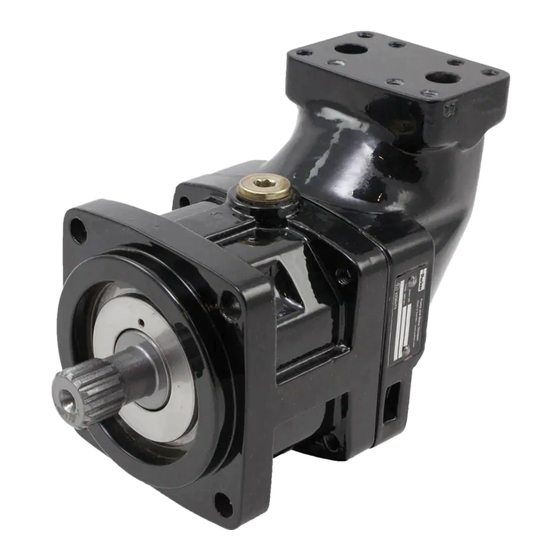
Parker F12 series Service Manual
Hide thumbs
Also See for F12 series:
- User manual ,
- Service manual (32 pages) ,
- Installation and start-up manual (9 pages)
Table of Contents

Summary of Contents for Parker F12 series
- Page 1 Bulletin HY30-5504-M1/UK Service Manual Series F12 Effective: June, 2006 Supersedes: August, 2003...
- Page 2 HEREIN OR RELATED ITEMS CAN CAUSE DEATH, PERSONAL INJURY AND PROPERTY DAMAGE. This document and other information from Parker Hannifin Corporation, its subsidiaries and authorized distributors provide product and/or system options for further investigation by users having technical expertise. It is important that you analyze all aspects of your application, including consequences of any failure, and review the information concerning the product or sys- tem in the current product catalogue.
- Page 3 F12 cross section 1. Barrel housing 2. Valve plate 3. Cylinder barrel 4. Piston with piston ring 5. Timing gear 6. Tapered roller bearing 7. Bearing housing 8. Shaft seal 9. Output/input shaft Parker Hannifin Pump and Motor Division Trollhättan, Sweden...
- Page 4 NOTE: The temperature should be measured at the utilized drain port. Continuous operation may require case flushing in order to meet the viscosity and temperature limitations. For further information we refer to: Catalgue HY17-8249/UK Parker Hannifin Pump and Motor Division Trollhättan, Sweden...
- Page 5 Lift off the barrel housing (item 110). Make sure that the valve plate doesn’t fall out when lifting the barrel housing off. Lift off the cylinder barrel (item 411). Take the shim (item 488) away. Parker Hannifin Pump and Motor Division Trollhättan, Sweden...
- Page 6 Service Manual HY30-5504-M1/UK Series F12 Lift off the barrel support (item 430). Remove the pistons (item 440). Remove the O-ring (item 221). Parker Hannifin Pump and Motor Division Trollhättan, Sweden...
- Page 7 Service Manual HY30-5504-M1/UK Series F12 Remove the retaining ring (item 237). Remove the seal carrier (item 231). Remove the O-ring (item 225). Parker Hannifin Pump and Motor Division Trollhättan, Sweden...
- Page 8 Series F12 Remove the retaining ring (item 478). Lift off the spacer washer (item 476). Place the bearing housing (item 211) on a tube. Push out the shaft (item 311) with a press. Parker Hannifin Pump and Motor Division Trollhättan, Sweden...
- Page 9 Service Manual HY30-5504-M1/UK Series F12 Remove the small tappered roller bearing (item 470). Tap the small bearing ring off with a mandrel. Tap the large bearing ring off with a mandrel. Parker Hannifin Pump and Motor Division Trollhättan, Sweden...
- Page 10 Service Manual HY30-5504-M1/UK Series F12 Place the ring gear (item 452) on a tube. Push out the shaft (item 311) with a press. Tube Parker Hannifin Pump and Motor Division Trollhättan, Sweden...
- Page 11 Use a tube to match the outer diameter off the bearing ring. Push on the bearing ring (item 470) in the bearing housing (item 211) with a press. Use a tube to match the outer diameter off the bearing ring. Parker Hannifin Pump and Motor Division Trollhättan, Sweden...
- Page 12 Series F12 Push on the Bearing (item 470) with a press until correct preload is achieved. Install the spacer washer (item 476). Install the retaining ring (item 478). Install the O-ring (item 225). Parker Hannifin Pump and Motor Division Trollhättan, Sweden...
- Page 13 Service Manual HY30-5504-M1/UK Series F12 Install the seal carrier (item 231). Install the retaining ring (item 237). Install the O-ring (item 221). Parker Hannifin Pump and Motor Division Trollhättan, Sweden...
- Page 14 Service Manual HY30-5504-M1/UK Series F12 Install the pistons (item 440). Install the barrel support (item 430). Install the shim (item 488). Parker Hannifin Pump and Motor Division Trollhättan, Sweden...
- Page 15 Put some grease on the valve plate (item 121) and install it into the barrel housing (item 110). Make sure you have installed the valve plate correct (see page 18). Install the barrel housing (item 110). Parker Hannifin Pump and Motor Division Trollhättan, Sweden...
- Page 16 105 ± 20 Nm Tools to be used to facilitate the installation of the tappered roller bearings. Type ØA ØB ØC F12-030 F12-040 F12-060 F12-080 F12-110 +0.2 0.5×45° ØC 0 ØB ØA -1 Parker Hannifin Pump and Motor Division Trollhättan, Sweden...
- Page 17 Remove the seal carrier (item 231). Tap the shaft seal out with hammer and mandrel. Tap the new shaft seal back with a tube and a hammer. The outside diameter on the tube is 65mm. Parker Hannifin Pump and Motor Division Trollhättan, Sweden...
- Page 18 L = L.H. rotation, pump operation R = R.H. rotation, pump operation Against cylinder barrel G = L.H. rotation, internal drain, motor operation X = Bi-directional, pump operation, high self priming speed Against cylinder barrel Parker Hannifin Pump and Motor Division Trollhättan, Sweden...
- Page 19 Also, check for leakage at the shaft seal and between the bearing and barrel housings. Series Normal Normal cu.in./min l/min gpm. l/min F12-030 F12-040 F12-060 F12-080 F12-090 F12-110 F12-125 Parker Hannifin Pump and Motor Division Trollhättan, Sweden...
- Page 20 Parker Hannifin Pump and Motor Division Flygmotorvägen 2 SE-461 82 Trollhättan Sweden Tel: +46 (0)520 40 45 00 Fax: +46 (0)520 371 05 www.parker.com...


Need help?
Do you have a question about the F12 series and is the answer not in the manual?
Questions and answers