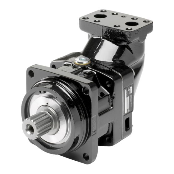
Parker F12 Series Service Manual
Bent axis, fixed displacement heavyduty motor/pump series
Hide thumbs
Also See for F12 Series:
- User manual ,
- Service manual (21 pages) ,
- Installation and start-up manual (9 pages)

Related Manuals for Parker F12 Series


Summary of Contents for Parker F12 Series
- Page 1 Bulletin HY30-5504-M1/UK Service Manual Series F12 Effective: September, 2019 Supersedes: April, 2011...
-
Page 2: Table Of Contents
FAILURE OR IMPROPER SELECTION OR IMPROPER USE OF THE PRODUCTS AND/OR SYSTEMS DESCRIBED HEREIN OR RELATED ITEMS CAN CAUSE DEATH, PERSONAL INJURY AND PROPERTY DAMAGE. This document and other information from Parker Hannifin Corporation, its subsidiaries and authorized distributors provide product and/or system options for further investigation by users having technical expertise. It is important that you analyze all aspects of your application, including consequences of any failure, and review the information concerning the product or sys- tem in the current product catalogue. Due to the variety of operating conditions and applications for these products or systems, the user, through its own analysis and testing, is solely responsible for making the final selection of the products and systems and assuring that all performance, safety and warning requirements of the application are met. The products described herein, including without limitation, product features, specifications, designs, availability and pricing, are subject to change by Parker Hannifin Corporation and its subsidiaries at any time without notice. Offer of Sale Please contact your Parker representation for a detailed ”Offer of Sale”. Parker Hannifin Pump and Motor Division Trollhättan, Sweden... -
Page 3: General Information
The F12’s have a simple and straightfor- The 40° angle between shaft and cylinder ward design with very few moving parts, barrel allows for a very compact, lightweight making them very reliable motors/pumps. motor/pump. The unique piston locking, timing gear and The laminated piston ring offers important bearing set-up as well as the limited num- advantages such as low internal leakage ber of parts add up to a very robust design and thermal shock resistance. with long service life and, above all, proven reliability. F12 cross section 1 2 3 4 5 6 7 8 9 1. Barrel housing 2. Valve plate 3. Cylinder barrel 4. Piston with piston ring 5. Timing gear 6. Tapered roller bearing 7. Bearing housing 8. Shaft seal 9. Output/input shaft Parker Hannifin Pump and Motor Division Trollhättan, Sweden... - Page 4 Mass moment of inertia (x10 ) (kg m 11.2 11.2 40.0 46.0 Weight (kg) 12.0 16.5 21.0 26.0 26.0 36.0 36.0 70.0 77.0 1) Intemittent: max 6 seconds in any one minute. 2) Selfpriming speed valid at sea level. 3) See also below, operating temperature. Operating temperature The following temperatures should not be exceeded (N shaft seals): Drain fluid: 90 FPM shaft seals (type V) can be used to 115 C drain fluid temperature. NOTE: The temperature should be measured at the utilized drain port. Continuous operation may require case flushing in order to meet the viscosity and temperature limitations. For further information we refer to: Catalogue HY30-8249/UK Parker Hannifin Pump and Motor Division Trollhättan, Sweden...
- Page 5 Service Manual HY30-5504-M1/UK Series F12 Disassemble Fasten the unit in a vice. Loosen the 4 boults (item 491). Disassemble the barrel housing (item 110). Make sure that the valve plate doesn’t fall out when lifting the barrel housing off. Remove the cylinder barrel (item 411). Take the shim (item 488) away. Parker Hannifin Pump and Motor Division Trollhättan, Sweden...
- Page 6 Service Manual HY30-5504-M1/UK Series F12 Remove the barrel support (item 430). Disassemble the pistons (item 440). Remove the O-ring (item 221). Parker Hannifin Pump and Motor Division Trollhättan, Sweden...
- Page 7 Service Manual HY30-5504-M1/UK Series F12 Disassemble the retaining ring (item 237). Remove the seal carrier (item 231). Remove the O-ring (item 225). Parker Hannifin Pump and Motor Division Trollhättan, Sweden...
- Page 8 Service Manual HY30-5504-M1/UK Series F12 Disassemble the retaining ring (item 478). Remove the spacer washer (item 476). Place the bearing housing (item 211) on a tube. Press uot the shaft (item 311) by pres- sing on the shaft end. Parker Hannifin Pump and Motor Division Trollhättan, Sweden...
- Page 9 Service Manual HY30-5504-M1/UK Series F12 Remove the small tappered roller bearing (item 470). Tap the small bearing ring off with a mandrel. Tap the large bearing ring off with a mandrel. Parker Hannifin Pump and Motor Division Trollhättan, Sweden...
- Page 10 Service Manual HY30-5504-M1/UK Series F12 Place the ring gear (item 452) on a tube. Press the shaft (item 311) out with a press. Tube Parker Hannifin Pump and Motor Division Trollhättan, Sweden...
- Page 11 Service Manual HY30-5504-M1/UK Series F12 Assemble F12-30/40/60/80/90/110 and 125 Press down the tappered roller bearing (item 460) and the ring gear (item 452) on the shaft with a press. Use a tube (see page 16). Press down the bearing ring (item 460) in the bearing housing (item 211) with a press. Use a tube to match the outer diameter off the bearing ring. Press down the bearing ring (item 470) in the bearing housing (item 211) with a press. Use a tube to match the outer diameter off the bearing ring. Parker Hannifin Pump and Motor Division Trollhättan, Sweden...
- Page 12 Service Manual HY30-5504-M1/UK Series F12 Press down the Bearing (item 470) with a press until correct preload is achieved. Install the spacer washer (item 476). Install the retaining ring (item 478). Install the O-ring (item 225). Parker Hannifin Pump and Motor Division Trollhättan, Sweden...
- Page 13 Service Manual HY30-5504-M1/UK Series F12 Install the seal carrier (item 231). Install the retaining ring (item 237). Install the O-ring (item 221). Parker Hannifin Pump and Motor Division Trollhättan, Sweden...
- Page 14 Service Manual HY30-5504-M1/UK Series F12 Install the pistons (item 440). Install the barrel support (item 430). Install the shim (item 488). Parker Hannifin Pump and Motor Division Trollhättan, Sweden...
- Page 15 Service Manual HY30-5504-M1/UK Series F12 Install the cylinder barrel (item 411). Ensure correct timing. (marking - punch mark) Put some grease on the valve plate (item 121) and install it into the barrel housing (item 110). Make sure you have installed the valve plate correct (see page 18). Install the barrel housing (item 110). Fasten two bolts and secure that the back- lash is between 0,1 - 0,3 mm. Check it with a feeler gauge in the drain port. At the same time double check the timing, (marking - punch mark). Parker Hannifin Pump and Motor Division Trollhättan, Sweden...
- Page 16 Tools to be used to facilitate the installation of the tappered roller bearings. Type ØA ØB ØC F12-030 F12-040 F12-060 F12-080/090 F12-110/125 F12-150/250 +0.2 0.5×45° 0.5x45 ØC 0 f C / +0.20 ØB f B f A / ØA -1 +0-1 Pressdon.eps Leif A./01-04-03 Parker Hannifin Pump and Motor Division Trollhättan, Sweden...
-
Page 17: Change Of Shaft Seal
Service Manual HY30-5504-M1/UK Series F12 Change of shaft seal Remove the retaining ring (item 237). Remove the seal carrier (item 231). Tap the shaft seal out with hammer and mandrel. Tap the new shaft seal back with a tube and a hammer. The outside diameter on the tube is 65mm. Parker Hannifin Pump and Motor Division Trollhättan, Sweden... -
Page 18: Valve Plates
Service Manual HY30-5504-M1/UK Series F12 Valve plates F12 Following valve plates can be fitted in F12. M = Bi-directional, motor operation Against cylinder barrel L = L.H. rotation, pump operation R = R.H. rotation, pump operation Against cylinder barrel G = L.H. rotation, internal drain, motor operation X = Bi-directional, pump operation, high self priming speed Against cylinder barrel Parker Hannifin Pump and Motor Division Trollhättan, Sweden... -
Page 19: Splitview F12-150
Service Manual HY30-5504-M1/UK Series F12 Splitview F12-150 Parker Hannifin Pump and Motor Division Trollhättan, Sweden... - Page 20 Service Manual HY30-5504-M1/UK Series F12 Assembly F12-150 1. Press down the tappered roller bea- 3. Assemble the lock washers (item ring (item 460) and the ring gear (item 474) and the round nut (item 475). Tap 452) on the shaft with a press. Use a in the lock washers to lock the round tube (see page 16). nut. 2. Carefully press down the tappered 4. Assemble the pistons (item 440). roller bearing (item 470) until correct Lubricate the ball sockets before preload of the bearing package is assembling. achieved. Use a tube (see page 16). Parker Hannifin Pump and Motor Division Trollhättan, Sweden...
-
Page 21: Assembling F12-150
Service Manual HY30-5504-M1/UK Series F12 Assembly F12-150 5. Assemble the valve plate (item 121) 7. Assemble the shims (item 488) in the barrel housing (item 110). Make and the guide spacer (item 486). Lo- sure you have installed the valve plate cate one opening in the guide spacer correct (see page 18). against the drain connection on the barrel housing. 6. Tap down the cylinder barrel (item 8. Assemble the bearing package with 411) with barrel retaining ring (item pistons. 431) and needle bearings (item 415) Use a plastic collar. Parker Hannifin Pump and Motor Division Trollhättan, Sweden... - Page 22 Service Manual HY30-5504-M1/UK Series F12 Assembly F12-150 9. Make sure the timing is correct. 11. Assemble the retaining ring (item 237). Lubricate the shaft seal before assembling the housing. 10. Assemble the shaft seal (item 233) 12. Assemble the bearing housing (item and the support ring (item 236). Locate 211), tap it down with a plastic hammer. the chamfer on the support ring down- Torque the screws to 220 ± 35 Nm. wards.Tap it down with a plastic collar. Parker Hannifin Pump and Motor Division Trollhättan, Sweden...
-
Page 23: Splitview F12-250
Service Manual HY30-5504-M1/UK Series F12 491*4 Splitview F12-250 493*3 488*3 415*2 413*3 440*9 Parker Hannifin Pump and Motor Division Trollhättan, Sweden... -
Page 24: Assembling F12-250
Service Manual HY30-5504-M1/UK Series F12 Assembly F12-250 1. Press down the tappered roller bea- 3. Assemble the lock washers (item ring (item 460) and the ring gear (item 474) and the round nut (item 475). Tap 452) on the shaft with a press. Use a in the lock washers to lock the round tube (see page 16). nut. 2. Carefully press down the tappered 4. Assemble the shaft seal (item 233) roller bearing (item 470) until correct and the support ring (item 236). Locate preload of the bearing package is the chamfer on the support ring down- achieved. Use a tube (see page 16). wards.Tap it down with a plastic collar. Assemble the retaining ring (item 237). Lubricate the shaft seal before assem- bling the housing. Parker Hannifin Pump and Motor Division Trollhättan, Sweden... - Page 25 Service Manual HY30-5504-M1/UK Series F12 Assembly F12-250 5. Tap down the bearing package into 7. Assemble the tap rol bearing (item the bearing housing (item 211) by using 425), the disc spring (item 433), the a plastic collar and a plastic hammer. spacer washer (item 426) and the re- taining ring (item 427). 6. Assemble the pistons (item 440). 8. Press down the bearing ring (item Lubricate the ball sockets before 425), the spacer sleeve (item 422), the assembling. neddle bearings (item 415) and the retaining ring (item 414). Locate the needle bearings against the retaining ring. Assemble the spring pins (item 413) and the sliding plate (item 424). Parker Hannifin Pump and Motor Division Trollhättan, Sweden...
- Page 26 Service Manual HY30-5504-M1/UK Series F12 Assembly F12-250 9. Assemble the cylinder barrel (item 11. Assemble the barrel housing. Make 411) on the pistons (item 440). Make sure the cylinder barrel is in correct sure the timing is correct. position by holding the barrel spindle (item 423). Tap the housing down with a plastic hammer. 10. Assemble the O-ring (item 222) on 12. Assemble the O-rings (item 223 the barrel housing (item 481). Lubricate and 224) on the end cap (item 111). the O-ring. Lubricate the O-rings. Parker Hannifin Pump and Motor Division Trollhättan, Sweden...
- Page 27 Service Manual HY30-5504-M1/UK Series F12 Assembly F12-250 13. Place the end cap on to the barrel 15. Knock down the end cap with a housing until the O-ring is entered. plastic hammer and fit shims (item 488) and hexagon screws (item 493). Torque the screws to 330 ± 10 Nm. 14. Fit a long screw (M12) to the barrel 16. Install the cap screw (item 428) that spindle and pull the barrel spindle up secures the barrel spindle. with a universal pliers. Parker Hannifin Pump and Motor Division Trollhättan, Sweden...
- Page 28 Service Manual HY30-5504-M1/UK Series F12 Assembly F12-250 17. Torque the cap screw to 40 - 45 Nm and back off 1/3 off a turn to obtain correct axial play. 18. Hit the cap screw one time to obtain back-lash. Make sure the back-lash is correct. Parker Hannifin Pump and Motor Division Trollhättan, Sweden...
- Page 29 Measure the drain flow for one minute; if it exceeds the maximum figures shown below, the unit is worn or damaged internally and should be replaced or repaired. Also, check for leakage at the shaft seal and between the bearing and barrel housings. Series Normal Normal (gpm, US) (l/min) (gpm, US) (l/min) F12-030 0.12 0.24 F12-040 0.16 0.32 F12-060 0.24 0.47 F12-080 0.32 0.64 F12-090 0.37 0.74 F12-110 0.44 0.87 F12-125 0.50 0.99 F12-250 0.64 1.60 Parker Hannifin Pump and Motor Division Trollhättan, Sweden...
- Page 30 Service Manual HY30-5504-M1/UK Series F12 Notes: Parker Hannifin Pump and Motor Division Trollhättan, Sweden...
- Page 31 Service Manual HY30-5504-M1/UK Series F12 Notes: Parker Hannifin Pump and Motor Division Trollhättan, Sweden...
- Page 32 Parker Hannifin Pump and Motor Division Flygmotorvägen 2 SE-461 82 Trollhättan Sweden Tel: +46 (0)520 40 45 00 Fax: +46 (0)520 371 05 www.parker.com...
Need help?
Do you have a question about the F12 Series and is the answer not in the manual?
Questions and answers