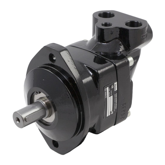
Parker F11 series Service Manual
Hydraulic motor/pump
Hide thumbs
Also See for F11 series:
- User manual ,
- Service and spare parts instruction (42 pages) ,
- Service spare parts list (40 pages)
Advertisement
Table of Contents
- 1 Table of Contents
- 2 Specifications
- 3 Design
- 4 Operational Check, Repair & Tools
- 5 Shaft Seal Replacement & Disassembly F11-005 through -150
- 6 Disassembly F11-250
- 7 Reconditioning and Replacement of Parts
- 8 Reassembly, F11-005 through -150
- 9 Reassembly, F11-250
- 10 Needle Bearing Installation, Cylinder Barrel
- 11 Parts Identification
- Download this manual
Advertisement
Table of Contents

Related Manuals for Parker F11 series


Summary of Contents for Parker F11 series
- Page 1 Bulletin HY30-5503-M1/UK Service Manual Series F11 Effective: February, 2006 Supersedes: February, 2001...
-
Page 2: Table Of Contents
The products described herein, including without limitation, product features, specifications, designs, availability and pricing, are subject to change by Parker Hannifin Corporation and its subsidiaries at any time without notice. Offer of Sale Please contact your Parker representation for a detailed ”Offer of Sale”. -
Page 3: Specifications
- 10 48±8 48±8 - 19 - 28 60±10 - 39 105±20 105±20 - 58 220±35 - 78 220±35 -110 -150 F11-5 through F11-150 220±35 -250 See Fig. 220±35 Nm 325±25 Nm F11-250 Parker Hannifin Pump and Motor Division Trollhättan, Sweden... -
Page 4: Design
Series 250 Series 5 through 150 Parker Hannifin Pump and Motor Division Trollhättan, Sweden... -
Page 5: Operational Check, Repair & Tools
Repair Tools and Supplies Metric Allen keys, retaining ring spanners, and a torque wrench with suitable metric sockets are required for the disassembly and assembly of the F11 series, plus common hand tools. Special tool for F11-250 no longer available. -
Page 6: Shaft Seal Replacement & Disassembly F11-005 Through -150
2. Mark the pistons and the corresponding ball sockets with a felt-tipped pen. 3. Remove the pistons by pulling them out when in line Dia."D" with the shaft as shown. 3 mm Series Dia. "D" (mm) F11- 5 Parker Hannifin Pump and Motor Division Trollhättan, Sweden... - Page 7 fits snugly around the shaft and supports the ring gear. The shaft can now be pressed out. Parker Hannifin Pump and Motor Division Trollhättan, Sweden...
-
Page 8: Disassembly F11-250
The shaft assembly can also be removed by grasping the housing and carefully hitting the shaft against a wooden block. Parker Hannifin Pump and Motor Division Trollhättan, Sweden... -
Page 9: Reconditioning And Replacement Of Parts
If play indicated in the figure is exceeded then re- place all piston and ring assemblies in the unit. Never replace individual worn piston and ring assemblies. Max .0.2 mm Parker Hannifin Pump and Motor Division Trollhättan, Sweden... -
Page 10: Reassembly, F11-005 Through -150
From the front, when installed, it looks the same as the M plate. post, install the hold-down ring and the leaf spring, and secure the spring with the locating pin. Parker Hannifin Pump and Motor Division Trollhättan, Sweden... - Page 11 11. Install the bearing housing with a new shaft seal on the shaft/bearing assembly, being careful not to cut or otherwise damage the seal. Cross-torque the cap screws according to specifications on page 3. Parker Hannifin Pump and Motor Division Trollhättan, Sweden...
-
Page 12: Reassembly, F11-250
Install the three cap screws and tighten according to bore, and position the cylinder barrel assembly on the ring specification (page 3). gear as shown so that the timing marks are lined up. Parker Hannifin Pump and Motor Division Trollhättan, Sweden... -
Page 13: Needle Bearing Installation, Cylinder Barrel
2. The second needle bearing should be located against the one previously installed. Note When installing the needle bearings, the marked end of the cage should face agains the gears on the cylinder barrel. Parker Hannifin Pump and Motor Division Trollhättan, Sweden... -
Page 14: Parts Identification
Barrel Retaining Ring Bearing Ring Leaf Spring Pivot Pin Piston Assy Piston Ring Ring Gear Taper Roller Bearing Spacer Ring Taper Roller Bearing Lock Washer Round Nut Guide Spacer Shim Hex Socket Screw Parker Hannifin Pump and Motor Division Trollhättan, Sweden... - Page 15 Piston Assy Piston Ring Ring Gear Taper Roller Bearing Cone Taper Roller Bearing Cup Spacer Ring Taper Roller Bearing Lock Washer Round Nut Barrel Housing Shim Hex Socket Screw Hex Socket Screw Parker Hannifin Pump and Motor Division Trollhättan, Sweden...
- Page 16 Parker Hannifin Pump and Motor Division Flygmotorvägen 2 SE-461 82 Trollhättan Sweden Tel: +46 (0)520 40 45 00 Fax: +46 (0)520 371 05 www.parker.com...
Need help?
Do you have a question about the F11 series and is the answer not in the manual?
Questions and answers