ALLEN & HEATH DT164-W - Dante I/O Expander Manual
- Getting started manual (9 pages)
Advertisement
Introduction
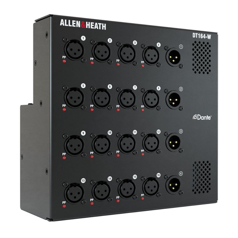
The DT164-W is a fixed installation Dante I/O expander for Allen & Heath digital mixing systems. It provides 16 remote controlled mic/line preamps and 4 XLR line outputs. It connects to the Dante network over a single Cat5 cable, or two cables for redundancy.
The DT164-W can be operated freestanding, mounted in a floor pocket, mounted on a wall, or flush mounted in a wall. Different power options are provided to suit the application.
 This product must be installed by a professional installer or qualified electrician.
Contents
Check that you have received the following with your DT164-W unit:
- Optional gland module (part number 004-1097) for permanent AC mains wiring installation.
- Mounting frame (AA11504) for in-wall or wall surface mounting.
- 6x M4 6mm T20 screws (AB2921) for mounting the DT164-W to the mounting frame.
Software and firmware
Visit the Audinate website to learn more about Dante, and download Dante Controller to route audio and configure devices on a Dante network: https://www.audinate.com/
 Preamp control of the DT164-W by an SQ mixer requires SQ firmware V1.4 or higher and SQ Dante card firmware V1.0.5 or higher.
Preamp control of the DT164-W by a dLive mixer requires dLive firmware V1.8 or higher and a dLive M-DL-Dante 64x64 or 128x128 card. Use of the iLive/GLD M-Dante card is not supported.
Check www.allen-heath.com for the latest DT164-W firmware and instructions on how to update it.
Connection

Redundant mode

Switched mode (daisy chain example)

Switched mode (digital split example)
Setting clock and patching signals
Use Dante Controller's Routing tab to patch signals between Dante devices. When a valid DT164-W socket is routed to a dLive / SQ Dante card, and patched to an Input channel, the dLive / SQ will present preamp gain, +48V and Pad controls for the socket.
Use Dante Controller's Clock Status tab to select the Dante network leader. The DT164-W should always be a clock follower on the Dante network, with the mixer typically set to "Preferred Leader" and "Enable Sync To External".
Top panel and power options

- Dante Secondary
Can be set to Redundant mode or to Switched mode for connection to multiple devices, for example two mixing consoles. Set the port mode in Dante Controller. - Dante Primary
EtherCon port for connection to the Dante network. The cable carries the audio signals as well as preamp control data. - Reset Network settings
Hold down the recessed switch for 10 seconds to reset the network settings for the DT164-W. This will delete any static IP address and revert to factory default (DHCP / zero-conf). - DC 12V Input
Can be used instead of AC mains to power the unit where adequate DC distribution is provided in a building. Can also be used as a backup power supply in case of mains failure. - Mains power input
The built-in universal PSU accepts voltages from 100 to 240V AC 50/60Hz. A module with IEC inlet is fitted by default. An optional module is provided for permanent installation, with knockout holes to accept a cable gland.
Replacement of the IEC AC inlet module and mains wiring for permanent installation must be performed by a qualified electrician. See instructions later in this guide.
Front panel

- Input sockets
Balanced XLR mic/line inputs with +48V Phantom Power indicator. The preamps are built into the DT164-W and their Gain, Pad and +48V are controlled from the network.
The +48V indicator detects voltage at the socket whether supplied by the DT164-W or received from an external source. - Output sockets
Balanced XLR outputs operating at nominal +4dBu level. - Vents
Ensure good ventilation at the front of the unit. Avoid obstruction of vents while operating. Avoid dirt or liquid ingress.
Installation – mounting

To prevent injury, this apparatus must be securely attached to the floor/wall in accordance with the installation instructions.
Mounting on a wall
Use the mounting frame AA11504 in the orientation shown below. Fix the frame to the wall using appropriate fixings or screws for the type of wall, then align the threaded inserts on the sides of the DT164-W with the frame, and secure the unit in place with the 6x M4 6mmT20 screws provided.

Flush mounting in a wall
Use the mounting frame AA11504 in the orientation shown below. Align the threaded inserts on the sides of the DT164-W with the frame, and secure the unit in place with the 6x M4 6mm T20 screws provided. Connect the power and Cat5 cable/s, then fix the assembly to the wall using appropriate fixings or screws for the type of wall.

Floor mounting
The DT164-W can be mounted in a floor box / stage pocket / dip trap. It must be installed in accordance with local installation and wiring regulations. We recommend using the ACE Backstage 174SLBK stage pocket system for use with the DT164-W.
Other options
The DT164-W will fit a 12x12" NEMA Type 1 / IP10 box or equivalent. A custom mounting frame might be required.
Permanent installation with the gland module
Replacement of the IEC AC inlet module and mains wiring for permanent installation must be performed by a qualified electrician and carried out in accordance with local wiring regulations.
To replace the IEC module:
- Remove the 4 screws using a Torx T8 driver.
- Pull out the module and unplug the harness at the bottom of the assembly.
![]()
- Fit a suitable cable gland or grommet appropriate to the cable wire size to the gland module plate.
![]()
- Run the mains cable through the gland. Minimum cable size 0.75mm2 or 20 AWG.
- Wire the mains cable to the terminal connector on the gland module, paying attention to polarity and earth grounding as indicated on the module.
![]()
- Securely tighten the cable gland around the cable.
- Re-plug the internal harness into the bottom of the gland module.
- Secure the module to the unit with the 4x T8 screws.


POWER DISCONNECTION
The mains supply disconnect device is the installation all pole circuit breaker or the switched fused outlet which must be labelled and must be accessible so as to be readily operable when the appliance is in use.
Dimensions

Specification
| Mic/Line XLR Inputs | Balanced XLR, +48V phantom power |
| Mic/Line Preamp | Fully recallable |
| Input Sensitivity | -60 to +15dBu |
| Analogue Gain | +5 to +60dB, 1dB steps |
| Pad | -20dB Active PAD |
| Maximum Input Level | +30dBu (PAD in) |
| Input Impedance | >4kΩ (Pad out), >10kΩ (Pad in) |
| Mic EIN | -127dB with 150Ω source |
| Analogue XLR Outputs | Balanced, Relay protected |
| Output Impedance | <75Ω |
| Nominal Output | +4dBu = 0dB meter reading |
| Maximum Output Level | +22dBu |
| Residual Output Noise | -92dBu (muted, 20-20kHz) -90dBu (muted, 20-40kHz) |
| Dante | Switched or Redundant mode, 48kHz/96kHz |
| Power and Temperature | |
| Mains Voltage Operating Range | 100-240V AC, 50/60Hz |
| Mains Power Consumption | 35W max |
| DC Input | 12V DC, 3A max |
| Operating Temperature Range | 0°C to 40°C (32°F to 104°F) |
| Dimensions and Weight | Width x Depth x Height x Weight |
| DT164-W | 210 x 87 x 210 mm x 3.2kg (8.25" x 3.5" x 8.25" x 7lbs) |
Register your product with Allen & Heath online at: http://www.allen-heath.com/support/register-product/
Documents / Resources
References
![www.audinate.com]() Audinate - Pioneering the future of AV
Audinate - Pioneering the future of AV![www.allen-heath.com]() Product Support - Allen & Heath
Product Support - Allen & Heath![www.allen-heath.com]() Allen & Heath - Heard Everywhere
Allen & Heath - Heard Everywhere
Download manual
Here you can download full pdf version of manual, it may contain additional safety instructions, warranty information, FCC rules, etc.
Advertisement


Need help?
Do you have a question about the DT164-W and is the answer not in the manual?
Questions and answers