Table of Contents
Advertisement
Quick Links
MICROTECH
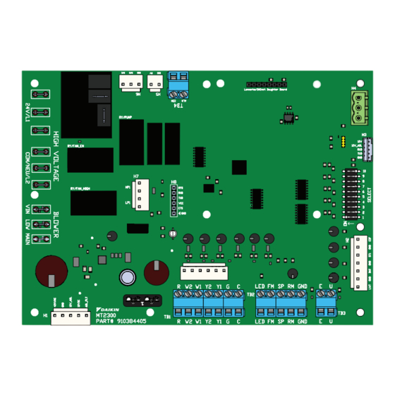
MT2300 UNIT CONTROLLER WITH MT2310 I/O EXPANSION BOARD
• R-32 REFRIGERANT WATER SOURCE HEAT PUMPS
©2024 DAIKIN APPLIED | (800) 432.1342
CONTROLLER
®
RY/PUMP
RY/PUMP
RY/FAN_EN
RY/FAN_EN
H7
H7
RY/FAN_HIGH
RY/FAN_HIGH
MT2300
MT2300
H1
H1
PART# 910384405
PART# 910384405
TB1
TB1
H4
H4
H8
H8
LED
LED FM
FM SP
SP RM
R R W2
W2 W1
W1 Y2
Y2 Y1
Y1 G G
C C
TB2
TB2
TB1
TB1
R R
W2
W2 W1
W1 Y2
Y2 Y1
Y1 G G
C C
LED
LED FM
FM SP
SP RM
H5
H5
PWM WSE
PWM
WSE GND
GND HGR
HGR GND
GND
AUX1 GND
AUX1
LEARN MORE AT DAIKINAPPLIED.COM
OPERATION MANUAL
OM 1364-1
OCTOBER 2024
H4
H4
H3
H3
10 10
9 9
8 8
7 7
6 6
5 5
4 4
3 3
2 2
1 1
RM GND
GND
E E
U U
TB3
TB3
E E
U U
RM GND
GND
H6
H6
GND AUX2
AUX2 GND
GND RV2
RV2 GND
GND COMP2
COMP2 GND
GND
Advertisement
Table of Contents

Related Manuals for Daikin MicroTech MT2300


Summary of Contents for Daikin MicroTech MT2300
- Page 1 PWM WSE WSE GND GND HGR HGR GND AUX1 AUX1 GND GND AUX2 AUX2 GND GND RV2 RV2 GND GND COMP2 COMP2 GND • R-32 REFRIGERANT WATER SOURCE HEAT PUMPS LEARN MORE AT DAIKINAPPLIED.COM ©2024 DAIKIN APPLIED | (800) 432.1342...
-
Page 2: Table Of Contents
©2024 Daikin Applied, Minneapolis, MN. All rights reserved throughout the world.This document contains the most current product information as of this printing. Daikin Applied Americas Inc. has the right to change the information, design, and construction of the product represented within the document without prior notice. -
Page 3: Safety Information
® Danger indicates a hazardous situation, which will result in death or serious • IM 1363 - MicroTech MT2300 Water Source Heat Pump injury if not avoided. Unit Controller BACnet MS/TP Network Integration • ED 19129 - MicroTech MT2300 Water Source Heat Pump... -
Page 4: Connections And Terminals
Y1 G G LED FM FM SP SP RM RM GND PWM WSE WSE GND GND HGR HGR GND AUX1 AUX1 GND GND AUX2 AUX2 GND GND RV2 RV2 GND GND COMP2 COMP2 GND DAIKIN APPLIED MICROTECH 2300 UNIT CONTROLLER... -
Page 5: Unit Controller And Control Modules
CONNECTIONS AND TERMINALS Unit Controller and Control Modules Connector Type Signal Description COM/ I/O Descriptions LIVE x 3 Input COMP1 Line2 Control Voltage NEU/L2 Daughter BACnet BACnet MS/TP Only Board Table 1: MT2300 unit controller connector and terminal descriptions Table 2: MT2310 I/O board connectors and terminals Connector Type Signal... -
Page 6: Replacing Unit Controller
To help prevent damage during service, use static discharge wrist straps. Static discharge wrist straps are grounded to the heat pump chassis through a 1M ohm resistor. DAIKIN APPLIED MICROTECH 2300 UNIT CONTROLLER... - Page 7 CONfIgURATION DIP SWITCHES Table 3: MT2300 Main board DIP switch settings Table 4: MT2310 I/O expansion module DIP switch settings Switch Description Position Model/Options Switch Description Position Model/Options SW1 = OFF (0) Normal Operation Normal/Test Variable Speed Fan Row Mode Variable Fan Selection (1 to 16), used SW1 = ON (1)
-
Page 8: Functionality
A contact closure between terminals U and C on the The MT2300 is the base unit controller for the Daikin Applied MT2300 unit controller will place the unit into the water source heat pump control platform. The MT2300 controls unoccupied mode for night setback/setup operation. -
Page 9: Control Outputs
fUNCTIONALITy Control Outputs LED Indicators • The thermostat alarm output: Will be energized when When the unit controller or I/O boards are communicating a there are fault conditions presently active. Without any fault certain fault or mode, the LED indicator will flash a designated conditions active, the alarm output shall be de-energized. -
Page 10: Operation
CFM output increases. The compressor minimum on timer of 180 seconds starts. The reversing valve will de-energize 5 seconds after the compressor starts. The fan CFM output is now determined by the MT2310 I/O DAIKIN APPLIED MICROTECH 2300 UNIT CONTROLLER... - Page 11 OPERATION board configuration switches SW1-SW4 and the corresponding the room setpoint conditions are satisfied, the electric heater will stage 1 CFM. If a two stage thermostat is used, a further demand turn off and the fan will either cycle off (fan switch “AUTO”) or for cooling will change (increase) the CFM output of the EC fan continue to operate (fan switch “ON”...
- Page 12 BACnet (factory default of 65°F). temperature increases above the changeover temperature, • On a call from Y1 or cooling stage 1 setpoint, and the EWT waterside economizer mode will be suspended and the unit will DAIKIN APPLIED MICROTECH 2300 UNIT CONTROLLER...
-
Page 13: Electric Heat Controls
OPERATION When Compressor is Unavailable resume normal mechanical cooling mode with stage 1 of the thermostat or network setpoint now starting the compressor. • Auxiliary Heat Stage 1 output energizes upon activation of “Heating – Stage 1. NOTICE • Auxiliary Heat Stage 2 output energizes upon activation To prevent compressor cycling and all compressors from starting up together of Heating –... -
Page 14: Thermostat Inputs
MT2300 baseboard (TB1-1), when energized from the thermostat, enables Waterside Economizer operation and the W4 input (TB1-5) on the MT2310 I/O expansion module will act as a Y3 third stage of cooling. DAIKIN APPLIED MICROTECH 2300 UNIT CONTROLLER... -
Page 15: Optional Features
OPTIONAL fEATURES Optional Features Two Compressor Option Compressor Availability Selection Heating Source Selection On two compressor units, Compressor Availability configuration switch allows you to select which compressors are available for Heating source selection provides a method to disable the operation. If a compressor needs to be disabled in order to be compressor operation when in the heating mode. -
Page 16: Dehumidification Only
The unit will only respond to a call for dehumidification whenever temperature is satisfied and the return air temperature is 68°F or the return air temperature is 68°F or greater. greater. If the controller detects the need for heating or cooling, DAIKIN APPLIED MICROTECH 2300 UNIT CONTROLLER... -
Page 17: Waterside Economizer
OPTIONAL fEATURES Waterside Economizer Items Required • Humidistat Application: • Return air sensor The MT2300 controls the waterside economizer. Upon a call Unit Control Settings for economizer operation via TB1-3, HST on the MT2310 I/O expansion board, for units without hot gas reheat or Y1 on the •... -
Page 18: Fault Modes
60 second fixed defrost timer. 4 . Wait for the defrost timer to expire. 5 . If the alarm condition has cleared: — Return to normal operation. 6. If the alarm condition remains active: DAIKIN APPLIED MICROTECH 2300 UNIT CONTROLLER... -
Page 19: Low Suction Temperature Fault Cooling
fAULT MODES Remote Reset of Automatic Lockouts For Single Compressor Units: — Compressor High Capacity is turned off The Remote Reset feature provides the means to remotely reset — Compressor is immediately turned off, ignoring the automatic lockouts. There are (3) ways to accomplish a unit reset Compressor Minimum ON timer once the fault condition has been remedied: —... -
Page 20: Status Led Indication
Compressor 2 High Discharge Temp freeze setpoint (FFD) (SW 4 = ON) A2L Mitigation – Refrigerant Sensor Rapid Flash Mode Yellow Comp 1 Low Suction ST1 sensor temp below Fail A,T,N Temp (ST1) minimum setpoint DAIKIN APPLIED MICROTECH 2300 UNIT CONTROLLER... - Page 21 TROUBLESHOOTINg LED Activity Type Color Description 1 Flash Fault Yellow Compressor Low Voltage Brownout 2 Flash Fault Yellow Freeze Fault Detect (FFD) 3 Flash Fault Yellow Control Temp Sensor Fail 4 Flash Fault Yellow Entering Water Temp Sensor Fail 5 Flash Fault Yellow Leaving Water Temp Sensor Fail...
-
Page 22: Troubleshooting
• Check airflow (cooling operation). will be forced to high speed during this alarm and for a • Entering water and air temperatures should be within the minimum of 5 minutes after it has been resolved. operating limits. DAIKIN APPLIED MICROTECH 2300 UNIT CONTROLLER... - Page 23 TROUBLESHOOTINg A2L Alarm – Control Board Without Power LED Activity Type Color Description 4 Flash Fault Yellow Entering Water Temp Sensor Fail LED Activity Type Color Description • Check connection of entering water temperature sensor on A2L Mitigation – Control Board 9 Flash Fault MT2310 I/O expansion board terminal H4 pins 1 and 2.
- Page 24 68°F. Waterside Economizer Low Temp Cutout (WSE Control & Call for Cooling) LED Activity Type Color Description 9 Flash Mode Green WSE Low Temp Cutout • Entering water temperature is below 45°F. DAIKIN APPLIED MICROTECH 2300 UNIT CONTROLLER...
-
Page 25: A2L Leak Detection Sensor And Board Service
A2L Leak Detection System A2L Leak Detection Sensor and Daikin Applied WSHP units that have above 4 lbs. of refrigerant Board Service per circuit and have a factory installed leak detection system. The A2L leak detection system consists of the following parts: •... - Page 26 Sensor 3 Pressure reported value. Not available for now. Sensor 4 Address GID14 GID14 + 7 Sensor 4 Address Sensor 4 Level 65535 Sensor 4 LFL reported value. For instance value = 200, then LFL is 20% DAIKIN APPLIED MICROTECH 2300 UNIT CONTROLLER...
- Page 27 A2L DETECTION AND MITIgATION GID id Name Min Limit Max Limit Default Description Sensor 4 State 65535 Sensor 4 current state. Value = 2, then state is "run" Sensor 4 Faults 65535 Sensor 4 internal faults reported. For instance value = 0, then no faults. Sensor 4 Temperature -400 Sensor 4 Temperature reported value.
- Page 28 1 - 8 0 0 - 4 3 2 - 1 3 4 2 | 7 6 3 - 5 5 3 - 5 3 3 0 LEARN MORE AT DAIKINAPPLIED.COM PART NUMBER: OM1364-1 © 2024 DAIKIN APPLIED | (800) 432.1342 | WWW.DAIKINAPPLIED.COM...
Need help?
Do you have a question about the MicroTech MT2300 and is the answer not in the manual?
Questions and answers