
Related Manuals for Daikin MT6210


Summary of Contents for Daikin MT6210
- Page 1 INSTALLATION MANUAL IM 1365-1 NOVEMBER 2024 MT6210 LEAK MITIGATION ® CONTROLLER FOR UNITS EQUIPPED WITH A2L REFRIGERANT LEARN MORE AT DAIKINAPPLIED.COM ©2024 DAIKIN APPLIED | (800) 432.1342...
-
Page 2: Table Of Contents
Hardware Specifications . . . . . . . . . . . . . . . . . . . . . . 18 ©2024 Daikin Applied, Minneapolis, MN. All rights reserved throughout the world. This document contains the most current product information as of this printing. -
Page 3: Safety Information
Polyolester Oil, commonly known as POE oil is a synthetic oil used in many refrigeration systems, and may be present in this Daikin Applied product. POE oil, if ever in contact with PVC/CPVC, will coat the inside wall of PVC/CPVC pipe causing environmental stress fractures. -
Page 4: Introduction
A2L refrigerant outside of the sealed refrigeration piping and communicates the concentration levels directly to the MT6210. The MT6210 board communicates the refrigerant detection system status to a unit controller and/or other system components to initiate the appropriate mitigation response. -
Page 5: Functionality
NOTICE A controller is not provided on every unit supplied by Daikin Applied. Daikin Applied is providing the equipment required for leakage mitigation detection with this control board and the leakage sensors but wiring and further unit system control logic may be required in the field. -
Page 6: Connections
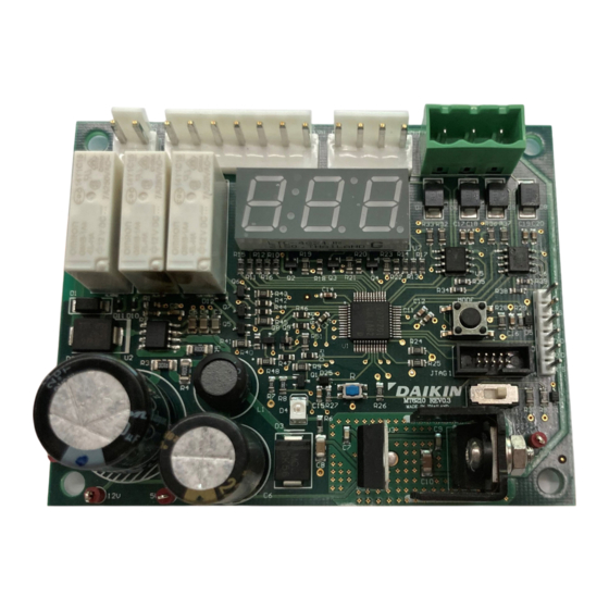
3. B 7. GND 4. 5V 3. GND 2. GND H4 – Service Port JTAG Interface Port (Factory Use Only) Table 1: MT6210 Connections Connector Label Description 24 VAC 24 VAC Control Power from Transformer Power Common / Chassis ground... -
Page 7: User Interface Functions
CONNECTIONS User Interface Functions Mode Button The Mode button is used to select user functions available on the LED display (“Display Modes” on page 10). Reset Button The Reset button forces the microprocessor into a hardware reset, interrupting normal operations. This button is used only during the programming process (“Firmware Updating Procedure”... -
Page 8: Sequence Of Operation
SEQUENCE OF OPERATION Sequence of Operation Once the power-up sequence is complete, the MT6210 enters a normal run state. During the run state, the control monitors the Power-Up Modbus networks and maintains the digital and binary outputs while executing the following specific activities: At power-up, the MT6210 initiates the microprocessor and then begins establishing the two Modbus communication networks. -
Page 9: Fault - Abnormal System Operation
Open Closed Relay of this self-test over the Modbus network to the MT6210. NOTE 1: If a leak is detected, the relay for the supply air fan will energize or de- energize depending on conditions shown in this table. NOTE 2: Shaded cells represent de-engergized relays (Off). -
Page 10: Display Modes
Display 1. Each entry will be preceded by the order number in the history buffer. 2 . Alarms are displayed as a single entry indicating the sensor that exceeded the %LFL threshold. DAIKIN APPLIED MT6210 A2L MITIGATION CONTROL... -
Page 11: Manual Test Mode
— Sensor address — LFL level WARNING — Sensor state Placing the MT6210 into Manual Test Mode may initiate a system mitigation — Sensor faults response, including energizing fans, disabling compressors, or other unit — Sensor temperature specific operational responses. Ensure unit is prepared for operation and safety precautions are followed prior to entering Manual Test Mode. - Page 12 Sensor 5 state (See Note 2) Sensor 5 Faults 65535 Sensor 5 internal fault Sensor 5 Temperature -400 Sensor 5 temperature (°Cx10) Sensor 5 Humidity 1000 Sensor 5 humidity (RHx10) Sensor 5 Pressure 4000 Sensor 5 pressure (future use) DAIKIN APPLIED MT6210 A2L MITIGATION CONTROL...
- Page 13 DISPLAy MODES GID # GID Name Minimum Value Maximum Value Default Value Description Sensor 6 Address GID14 GID14+7 Sensor 6 Address Sensor 6 Level 1000 Sensor 6 LFL value (%LFLx10) Sensor 6 State Sensor 6 state (See Note 2) Sensor 6 Faults 65535 Sensor 6 internal fault Sensor 6 Temperature...
-
Page 14: Replacing Faulty Sensors
5 . Connect the unit wiring harness to the new sensor. Sensor Network Verification 6. Apply power to the controller/network. 7 . Observe the MT6210 display and record the network status When a sensor failure is indicated, the current state of sensor summary. - Page 15 1. Acquire the needed number of new, unused replacement sensors sufficient to replace all sensors. Do not attempt to used previously installed sensors, as the MT6210 may not be able to properly address these sensors for replacement .
-
Page 16: Firmware Updating Procedure
1. Connect the 6-pin serial cable with the FTDI to USB interface to the board. The MT6210 has the Renesas RA2L1 microcontroller which has an embedded bootloader to allow updating functional firmware 2 . Set the mode switch to “BOOT”, then press the “RESET”... - Page 17 FIRMWARE UPDATING PROCEDURE 4 . A successful programming operation will display as shown Figure 9: Com4 - PuTTY Example Figure Figure 8: Operation Complete Example NOTE: If there is an “NG” for “no good” instead of OK, checks include if the board is in BOOT mode and it has been reset.
-
Page 18: Hardware Specifications
"Alarm" (2 series redundant N/C contacts) and "Customer" N/O contact 5A @ 250VAC; 3A @ 30VDC Comm Ports 2 RS485 ports: 1 configured as “Modbus Client” (sensors). 1 configured as “Modbus Server” (unit controller) Maximum Sensor Load (mA) 300 @ 5VDC DAIKIN APPLIED MT6210 A2L MITIGATION CONTROL... - Page 19 WWW.DAIKINAPPLIED.COM IM 1365-1...
- Page 20 1 - 8 0 0 - 4 3 2 - 1 3 4 2 | 7 6 3 - 5 5 3 - 5 3 3 0 LEARN MORE AT DAIKINAPPLIED.COM PART NUMBER: IM1365-1 © 2024 DAIKIN APPLIED | (800) 432.1342 | WWW.DAIKINAPPLIED.COM...
Need help?
Do you have a question about the MT6210 and is the answer not in the manual?
Questions and answers