Advertisement
Available languages
Available languages
Quick Links
LINK/ACT
1
2
RESET
5
6
9
10
13
14
17
18
21
22
PSU
FAN
SYS
3
4
7
8
11
12
15
16
19
20
23
24
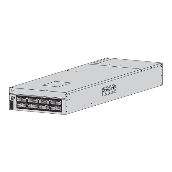
N9550-64D
DATA CENTER SWITCH
RECHENZENTRUMS-SWITCH
SWITCH DE CENTRE DE DONNÉES
データセンター用スイッチ
Quick Start Guide
Quick-Start Anleitung
Guide de Démarrage Rapide
クイックスタートガイド
25
26
29
30
33
34
37
38
41
42
45
46
49
50
53
54
57
58
61
62
27
28
31
32
35
36
39
40
43
44
47
48
51
52
55
56
59
60
63
64
V1.0
Advertisement

Subscribe to Our Youtube Channel
Related Manuals for FS N9550-64D


Summary of Contents for FS N9550-64D
- Page 1 LINK/ACT RESET N9550-64D DATA CENTER SWITCH RECHENZENTRUMS-SWITCH SWITCH DE CENTRE DE DONNÉES データセンター用スイッチ Quick Start Guide V1.0 Quick-Start Anleitung Guide de Démarrage Rapide クイックスタートガイド...
- Page 2 Introduction Thank you for choosing the N9550-64D Data Center Switch. This guide is designed to familiarize you with the layout of the switch and describes how to mount it. LINK/ACT RESET N9550-64D Accessories Power Cord x4 Grounding Cable x1 Mounting Bracket x2...
-
Page 3: Hardware Overview
M4 Screw x8 Slide rail and chassis rail x2 NOTE: The accessories may vary from illustration, please prevail in kind. NOTE: This power cord cannot be used with other devices, and other power cords should not be used with this device. Hardware Overview Front Panel Ports LINK/ACT... -
Page 4: Back Panel
Back Panel Grounding Point 100-240V~; 50-60Hz; 10A MAX 100-240V~; 50-60Hz; 10A MAX 1 3 5 2 4 6 100-240V~; 50-60Hz; 10A MAX LINK/ACT 100-240V~; 50-60Hz; 10A MAX RESET Fan Slots Power Suppies(AC) Installation Requirements Before installation, make sure that you have the following: Phillips screwdriver, ESD wrist strap, and loop cable ties for securing power cords. -
Page 5: Mounting The Switch
Mounting the Switch Rack Mounting 1. Secure the mounting brackets to the two sides of the switch with the screws. 2. Secure the slide rails and chassis rails to the rack with the screws and cage nuts. -
Page 6: Grounding The Switch
LINK/ACT RESET 3. Push the switch slightly into the rack along the slide rails and chassis rails and x the switch with the screws. Grounding the Switch 1 3 5 2 4 6 1. Connect one end of the grounding cable to a proper earth ground. 2. -
Page 7: Connecting The Console Port
Connecting the QSFP-DD Ports LINK/ACT RESET 1. Plug the compatible QSFP-DD transceiver into the QSFP-DD port. 2. Connect a ber optic cable to the ber transceiver. Then connect the other end of the cable to another ber device. WARNING: Laser beams will cause eye damage. Do not look into the bores of transceivers or optical bers without eye protection. -
Page 8: Connecting The Usb Port
Connecting the MGMT Port LINK/A CT RESET 1. Connect one end of a standard RJ45 Ethernet cable to a computer. 2. Connect the other end of the cable to the MGMT port on the switch. Connecting the USB Port LINK/A CT RESET Insert the Universal Serial Bus (USB) ash disk into the USB port for software and con guration backup and o ine software upgrade. -
Page 9: Connecting The Power
Connecting the Power 100-240V ~; 50-60Hz; 10A 1 3 5 2 4 6 100-240V ~; 50-60Hz; 10A 100-240V ~; 50-60Hz; 10A 100-240V ~; 50-60Hz; 10A 1. Plug the AC power cord into the power port on the switch. 2. Connect the other end of the power cord to an AC power source. WARNING: Do not install the power cord while the power is on. -
Page 10: Troubleshooting
Troubleshooting Power Module Failure Check whether the power module model matches the switch. Check whether the power module or the power cord is fully inserted in place, and then unplug and reinsert it. Check the dust accumulation of the power module. If there is much dust, please clean the dust. -
Page 11: Online Resources
Product Warranty FS ensures our customers that for any damage or faulty items due to our workmanship, we will o er a free return within 30 days from the day you receive your goods. This excludes any custom-made items or tailored solutions. - Page 12 Einführung Vielen Dank, dass Sie sich für den N9550-64D Rechenzentrums-Switch entschieden haben. Diese Anleitung soll Sie mit dem Aufbau des Switches vertraut machen und beschreibt, wie Sie ihn montieren. LINK/ACT RESET N9550-64D Zubehör Netzkabel x4 Erdungskabel x1 Vordere Montagehalterung x2...
- Page 13 M4-Schraube x8 Gleitschiene und Chassisschiene x2 HINWEIS: Bitte beachten Sie, dass das Zubehör von der Abbildung abweichen kann. HINWEIS: Dieses Netzkabel kann nicht mit anderen Geräten verwendet werden, und andere Netzkabel sollten nicht mit diesem Gerät verwendet werden. Hardware-Übersicht Ports an der Vorderseite LINK/ACT MGMT RESET...
- Page 14 Rückseite Erdungspunkt 100-240V~; 50-60Hz; 10A MAX 100-240V~; 50-60Hz; 10A MAX 1 3 5 2 4 6 100-240V~; 50-60Hz; 10A MAX LINK/ACT 100-240V~; 50-60Hz; 10A MAX RESET Lüfter-Steckplätze Netzteile (AC) Installationsanforderungen Vergewissern Sie sich vor der Installation, dass Sie Folgendes haben: Kreuzschlitzschraubendreher, ESD-Armband und Kabelbinder zur Sicherung der Stromkabel.
-
Page 15: Montage Des Switches
Montage des Switches Rack-Montage 1. Befestigen Sie die vorderen Montagehalterungen mit den Schrauben an den beiden Seiten des Switches. 2. Befestigen Sie die Gleitschienen und Chassisschienen mit den Schrauben und Kä gmuttern am Rack. - Page 16 LINK/ACT RESET 3. Schieben Sie den Switch entlang der Gleitschienen und Chassisschienen leicht in das Rack und befestigen Sie ihn mit den Schrauben. Erdung des Switches 1 3 5 2 4 6 1. Schließen Sie ein Ende des Erdungskabels an eine geeignete Erdung an. 2.
- Page 17 Anschließen der QSFP-DD-Ports LINK/ACT RESET 1. Verbinden Sie den kompatiblen QSFP-DD-Transceiver mit dem QSFP-DD-Port. 2. Schließen Sie ein LWL-Kabel an den Transceiver an. Schließen Sie dann das andere Ende des Kabels an ein anderes Glasfasergerät an. WARNUNG: Laserstrahlen können zu Augenschäden führen. Schauen Sie nicht ohne Augenschutz in die Bohrungen von Transceivern oder optischen Fasern.
- Page 18 Anschließen des MGMT-Ports LINK/A CT RESET 1. Schließen Sie ein Ende eines Standard-RJ45-Ethernet-Kabels an einen Computer an. 2. Schließen Sie das andere Ende des Kabels an den MGMT-Port des Switches an. Anschließen des USB-Ports LINK/A CT RESET Stecken Sie das USB-Flash-Laufwerk (Universal Serial Bus) in den USB-Port, um die Software und die Kon guration zu sichern und die Software o ine zu aktualisieren.
-
Page 19: Anschließen Der Stromversorgung
Anschließen der Stromversorgung 100-240V ~; 50-60Hz; 10A 1 3 5 2 4 6 100-240V ~; 50-60Hz; 10A 100-240V ~; 50-60Hz; 10A 100-240V ~; 50-60Hz; 10A 1. Stecken Sie das AC-Netzkabel in den Netzanschluss an der Rückseite des Switches. 2. Schließen Sie das andere Ende des Netzkabels an eine Netzstromquelle an. WARNUNG: Schließen Sie das Netzkabel nicht an, während das Gerät eingeschaltet ist. -
Page 20: Fehlerbehebung
Fehlerbehebung Ausfall des Leistungsmoduls Prüfen Sie, ob das Leistungsmodul zum Switch passt. Prüfen Sie, ob das Leistungsmodul vollständig eingesteckt ist. Ziehen Sie es dann heraus und stecken Sie es erneut ein. Wenn sich viel Staub im Leistungsmodul be ndet, befreien Sie es von jeglichem Staub. Wenn der Fehler weiterhin besteht, wenden Sie sich bitte an den technischen Support. - Page 21 Kontakt https://www.fs.com/de/contact_us.html Produktgarantie FS garantiert seinen Kunden, dass wir bei Schäden oder fehlerhaften Artikeln, die auf unsere Verarbeitung zurückzuführen sind, eine kostenlose Rückgabe innerhalb von 30 Tagen nach Erhalt der Ware anbieten. Dies gilt nicht für Sonderanfertigungen oder maßgeschneiderte Lösungen.
- Page 22 Introduction Nous vous remercions d'avoir choisi le switch N9550-64D pour centre de données. Ce guide est conçu pour vous familiariser avec la con guration du switch et décrit comment procéder à son installation. LINK/ACT RESET N9550-64D Accessoires Câble d'Alimentation x4 Câble de Mise à...
-
Page 23: Présentation Du Matériel
Vis M4 x8 Rail coulissant et rail du châssis x2 NOTE : Les accessoires peuvent varier par rapport à l'illustration, veuillez en tenir compte. NOTE : Ce cordon d'alimentation ne peut pas être utilisé avec d'autres appareils, et les autres cordons d'alimentation ne doivent pas être utilisés avec cet appareil. Présentation du Matériel Ports du Panneau Frontal LINK/ACT... -
Page 24: Panneau Arrière
Panneau Arrière Point de Mise à la Terre 100-240V~; 50-60Hz; 10A MAX 100-240V~; 50-60Hz; 10A MAX 1 3 5 2 4 6 100-240V~; 50-60Hz; 10A MAX LINK/ACT 100-240V~; 50-60Hz; 10A MAX RESET Emplacements pour Ventilateurs Alimentation (AC) Conditions d'Installation Avant l'installation, assurez-vous que vous disposez des éléments suivants : un tournevis Phillips, un bracelet ESD et des colliers de serrage pour la xation des câbles d'alimentation. -
Page 25: Installation En Rack
Installation du Switch Installation en rack 1. Fixez les supports de montage sur les deux côtés du switch à l'aide des vis. 2. Fixez les rails coulissants et les rails du châssis au rack à l'aide des vis et des écrous à cage. - Page 26 LINK/ACT RESET 3. Poussez légèrement le switch dans le rack le long des rails coulissants et des rails du châssis et xez le switch à l'aide des vis. Mise à la Terre du Switch 1 3 5 2 4 6 1.
- Page 27 Connexion des Ports QSFP-DD LINK/ACT RESET 1. Branchez l'émetteur-récepteur QSFP-DD compatible dans le port QSFP-DD. 2. Connectez un câble à bre optique à l'émetteur-récepteur à bre. Connectez ensuite l'autre extrémité du câble à un autre dispositif à bre optique. AVERTISSEMENT : Les faisceaux laser peuvent provoquer des lésions oculaires.
- Page 28 Connexion du Port MGMT LINK/A CT RESET 1. Connectez une extrémité d'un câble Ethernet RJ45 standard à un ordinateur. 2. Connectez l'autre extrémité du câble au port MGMT du switch. Connexion du Port USB LINK/A CT RESET Insérez le dispositif USB (Universal Serial Bus) dans le port USB pour la sauvegarde, con guration et la mise à...
-
Page 29: Branchement De L'alimentation
Branchement de l'Alimentation 100-240V ~; 50-60Hz; 10A 1 3 5 2 4 6 100-240V ~; 50-60Hz; 10A 100-240V ~; 50-60Hz; 10A 100-240V ~; 50-60Hz; 10A 1. Branchez le câble d'alimentation CA dans le port d'alimentation du switch. 2. Branchez l'autre extrémité du câble d'alimentation à une source d'alimentation en courant alternatif (CA). -
Page 30: Dépannage
Dépannage Défaillance du Module d'Alimentation Véri ez si le modèle de module d'alimentation est compatible avec le switch. Véri ez si le module d'alimentation ou le câble d'alimentation est bien inséré en place, puis débranchez-le et réinsérez-le. Véri ez l'accumulation de poussière sur le module d'alimentation. S'il y a une quantité importante de poussière, veuillez la retirer. -
Page 31: Garantie Du Produit
Garantie du Produit FS garantit à ses clients que tout article endommagé ou défectueux en raison de sa fabrication pourra être retourné gratuitement dans un délai de 30 jours à compter de la date de réception de la marchandise. Cette garantie ne s'applique pas aux articles fabriqués sur mesure ou aux solutions personnalisées. - Page 32 イントロダクション この度は、N����-��Dデータセンター用スイッチをご購入いただき、誠にありがとうござ います。 このガイドは、スイッチのレイアウトを理解し、ネットワークにスイッチを導入 する方法を説明するためのものです。 LINK/ACT RESET N����-��D アクセサリー 電源コードx� 接地ケーブルx� フロントマウントブラケットx� M�ネジx� M�ネジx�� ケージナットx��...
- Page 33 M�ネジx� スライドレールx� 注: 一部のアクセサリーはイラストと異なる場合があります。 注: この電源コードは他の機器には使用できません。また、他の電源コードはこ の機器に使用しないでください。 ハードウェア概要 フロントパネルポート MGMT LINK/ACT CONSOLE RESET QSFP-DD ポート 説明 QSFP-DD ���G接続用QSFPポート MGMT イーサネット管理用ポート CONSOLE シリアル管理用RJ��コンソールポート ソフトウェアと設定のバックアップおよびオフライン・ソフトウェ ア・アップグレード用ポート...
- Page 34 バックパネル 接地点 100-240V~; 50-60Hz; 10A MAX 100-240V~; 50-60Hz; 10A MAX 1 3 5 2 4 6 100-240V~; 50-60Hz; 10A MAX LINK/ACT 100-240V~; 50-60Hz; 10A MAX RESET ファンスロット 電源(AC) インストール要件 インストールする前に、以下のことを先にご用意ください。 プラスドライバー、ESDリストストラップ、電源コード固定用ループケーブルタイ。 M6ネジとケージナット。 �U以上の高さが利用可能な標準サイズの��インチ幅のラック。 ネットワーク機器接続用の標準RJ-��イーサネットケーブル。 設置環境: 作業環境の温度が�℃~��℃、高度が-��m~����m、相対湿度が�%~��%に保たれて いることを確認してください。 保管温度が-��℃~��℃、保管湿度が�%~��%に保たれていることを確認してくださ い。 水漏れ、水滴、結露、湿気のない場所に設置してください。 設置場所を埃のないようにしてください。...
- Page 35 スイッチの取り付け ラックマウント �. 前面取付けブラケットをスイッチの両側面にネジで固定します。 �. リアマウントブラケットをネジとケージナットでラックに固定します。...
- Page 36 LINK/ACT RESET �. スイッチをスライドレールに沿ってラックに少し押し込み、ネジでスイッチを固定しま す。 スイッチの接地 1 3 5 2 4 6 �. 接地ケーブルの一端を適切な接地点に接続します。 �. 接地ラグを、スイッチの背面パネルにある接地ポイントに、 ネジとワッシャで固定しま す。...
- Page 37 QSFP-DDポートの接続 LINK/ACT RESET �. 互換性のあるQSFP-DDモジュールをQSFP-DDポートに差し込みます。 �. 光ファイバケーブルをファイバモジュールに接続します。次に、ケーブルのもう一方の 端を別のファイバ機器に接続します。 警告: レーザー光線は目に損傷を与えます。目を保護せずに、トランシーバーや 光ファイバの穴をのぞき込まないでください。 コンソールポートの接続 100-2 40V~; 50-60 Hz; 10A LINK/A CT 100-2 40V~; 50-60 Hz; 10A RESET 100-2 40V~; 50-60 Hz; 10A 100-2 40V~; 50-60 Hz; 10A �. RJ��コネクタをスイッチのRJ��コンソールポートに挿入します。 �. コンソールケーブルのDB�メスコネクタをコンピュータのシリアルポートに接続します。...
- Page 38 MGMTポートの接続 LINK/A CT RESET �. 標準RJ��イーサネットケーブルの一端をコンピュータに接続します。 �. ケーブルのもう一方の端をスイッチのMGMTポートに接続します。 USBポートの接続 LINK/A CT RESET USBポートにユニバーサル・シリアル・バス(USB)フラッシュ・ディスクを挿入し、ソフト ウェアと設定のバックアップとオフライン・ソフトウェア・アップグレードを行います。...
- Page 39 電源の接続 100-240V ~; 50-60Hz; 10A 1 3 5 2 4 6 100-240V ~; 50-60Hz; 10A 100-240V ~; 50-60Hz; 10A 100-240V ~; 50-60Hz; 10A �. AC電源コードをスイッチの電源ポートに接続します。 �. 電源コードのもう一方の端をAC電源に接続します。 警告: 電源が入った状態で電源コードを取り付けないでください。...
- Page 40 トラブルシューティング 電源モジュールの故障 電源モジュールのモデルがスイッチと一致しているか確認してください。 電源モジュールまたは電源コードが所定の位置に完全に挿入されているか確認し、プ ラグを抜いて再度挿入してください。 電源モジュールのほこりの蓄積状況を確認してください。ほこりが多い場合は、ほこ りを掃除してください。 それでも故障が解決しない場合は、技術サポートまでご連絡ください。 ファンモジュールの故障 ファンが所定の位置に完全に挿入されているか確認し、引き抜いて再度挿入してくださ い。 シャーシの空気出口と空気入口が異物で塞がれていないか確認してください。 それでも故障が解決しない場合は、技術サポートまでご連絡ください。 シリアルポートの故障 シリアルポートケーブルがポートに正しく挿入されているか、シリアルポートケーブ ルの両端が正しく挿入されているか確認してください。 ボーレート、ストップビットなど、シリアルポートのパラメータ設定が正しいか確認 してください。 それでも故障が解決しない場合は、技術サポートまでご連絡ください。 MGMTポートの故障 ネットワークケーブルがポートに正しく差し込まれているか、ネットワークケーブル の両端が正しく差し込まれているかを確認してください。 IP、サブネットマスクなど、ネットワークインターフェイスのパラメータが正しく設 定されているか確認してください。 それでも故障が解決しない場合は、技術サポートまでご連絡ください。...
- Page 41 オンラインリソース ダウンロード https://www.fs.com/jp/products_support.html ヘルプセンター https://www.fs.com/jp/service/fs_support.html お問い合わせ https://www.fs.com/jp/contact_us.html 製品保証 FSでは、弊社の製造技術による破損や不良品については、商品をお受け取りになった日か ら��日以内であれば、無料で返品を承ります。ただし、これにはカスタム製品やオーダー メイドは含まれません。 保証:この製品は、材料または製造上の欠陥に対して�年間の限定保証を提供し ます。保証の詳細については、次のサイトでご確認ください: https://www.fs.com/jp/policies/warranty.html 返品:返品したい場合は、返品方法に関する情報が次のサイトにご覧ください: https://www.fs.com/jp/policies/day_return_policy.html...
-
Page 42: Compliance Information
Compliance Information Note: This equipment has been tested and found to comply with the limits for a Class A digital device, pursuant to part 15 of the FCC Rules. These limits are designed to provide reasonable protection against harmful interference when the equipment is operated in a commercial environment. - Page 43 2014/35/EU, 2011/65/EU und (EU)2015/863 konform ist. Eine Kopie der EU-Konformitätserklärung nden Sie unter www.fs.com/de/company/quality_control.html. FS.COM GmbH déclare par la présente que ce dispositif est conforme à la Directive 2014/30/EU, 2014/35/EU, 2011/65/EU et (EU)2015/863. Une copie de la Déclaration de Conformité de l'UE est disponible à l'adresse suivante https://www.fs.com/fr/company/quality_control.html.
- Page 44 UKCA Hereby, FS.COM Innovation Ltd declares that this device is in compliance with the Directive SI 2016 No. 1091, SI 2016 No. 1101and SI 2012 NO. 3032. FS.COM INNOVATION LTD Unit 8, Urban Express Park, Union Way, Aston, Birmingham, B6 7FH, United Kingdom...
- Page 45 WEEE Waste Electrical and Electronic Equipment (WEEE) This appliance is labelled in accordance with European Directive 2012/19/EU concerning waste electrical and electronic equipment (WEEE). The Directive determines the framework for the return and recycling of used appliances as applicable throughout the European Union.
Need help?
Do you have a question about the N9550-64D and is the answer not in the manual?
Questions and answers