Table of Contents
Advertisement
1F
2F
3F
4F
5F
6F
7F
8F
9F
10F
Sta tus
ID
N5 860 -48
SC
1F
2F
3F
4F
5F
6F
7F
8F
9F
10F
Sta tus
ID
N8 560 -48
BC
MG MT
Lin k
1F
2F
AC T
5F
6F
ID
Sta tus
CON SOL E
N8 56 0-6 4C
3F
4F
7F
8F
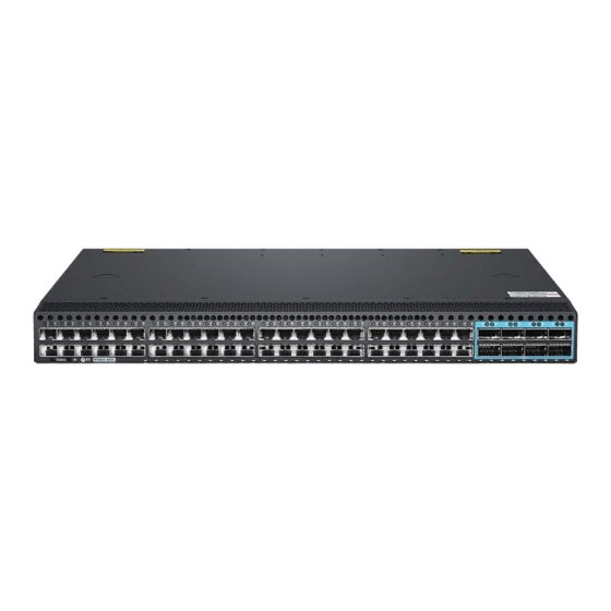
N5860 and N8560 Series 10G/25G/100G Switches
L3 DATA CENTER SWITCHES
Quick Start Guide
11F
12F
13F
14F
15F
16F
17F
18F
19F
20F
21F
22F
23F
24F
25F
26F
27F
28F
29F
30F
31F
11F
12F
13F
14F
15F
16F
17F
18F
19F
20F
21F
22F
23F
24F
25F
26F
27F
28F
29F
30F
31F
9F
10F
13F
14F
17F
18F
21F
22F
25F
26F
29F
30F
11F
12F
15F
16F
19F
20F
23F
24F
27F
28F
31F
32F
V1.0
32F
33F
34F
35F
36F
37F
38F
39F
40F
41F
42F
43F
44F
45F
46F
47F
48F
49F
50F
51F
32F
33F
34F
35F
36F
37F
38F
39F
40F
41F
42F
43F
44F
45F
46F
47F
48F
49F
50F
51F
33F
34F
37F
38F
41F
42F
45F
46F
49F
50F
53F
54F
57F
35F
36F
39F
40F
43F
44F
47F
48F
51F
52F
55F
56F
59F
52F
53F
54F
55F
56F
100 G
52F
53F
54F
55F
56F
100 G
58F
61F
62F
60F
63F
64F
Advertisement
Table of Contents


Need help?
Do you have a question about the N5860 Series and is the answer not in the manual?
Questions and answers