Table of Contents
Advertisement
Available languages
Available languages
Quick Links
1
N8 55 0-2
3
4C D8 D
5
7
SY S ID
PS U FA
QSFP 56
N
QSFP 56
2
4
6
8
N8550-24CD8D
DATA CENTER SWITCH
RECHENZENTRUMS-SWITCH
SWITCH DE CENTRE DE DONNÉES
データセンター用スイッチ
Quick Start Guide
Quick Start Anleitung
Guide de Démarrage Rapide
クイックスタートガイド
9
11
13
15
17
19
QSFP 56
21
23
QSFP 56
10
QSFP 56
12
14
QSFP 56
16
18
20
22
24
V1.0
25
QSFP -DD
26
27
QSFP -DD
28
29
QSFP -DD
30
31
QSFP -DD
32
Advertisement
Table of Contents

Related Manuals for FS N8550-24CD8D


Summary of Contents for FS N8550-24CD8D
- Page 1 QSFP 56 QSFP 56 QSFP 56 QSFP 56 QSFP 56 QSFP -DD QSFP -DD QSFP -DD QSFP -DD N8550-24CD8D DATA CENTER SWITCH RECHENZENTRUMS-SWITCH SWITCH DE CENTRE DE DONNÉES データセンター用スイッチ Quick Start Guide V1.0 Quick Start Anleitung Guide de Démarrage Rapide...
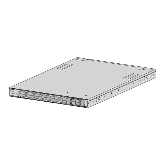
- Page 2 Introduction Thank you for choosing the N8550-24CD8D Data Center Switch. This guide is designed to familiarize you with the layout of the switch and describes how to mount it. N8550-24CD8D QSFP56 QSFP56 QSFP56 QSFP56 QSFP56 QSFP56 QSFP-DD QSFP-DD QSFP-DD QSFP-DD...
-
Page 3: Hardware Overview
The accessories may vary from illustration, please prevail in kind. NOTE: This power cord cannot be used with other devices, and other power cords should not be used with this device. Hardware Overview Front Panel Ports N8550-24CD8D QSFP56 QSFP56 QSFP56 QSFP56 QSFP56... -
Page 4: Installation Requirements
Installation Requirements Before the installation, make sure that you have the following: Phillips screwdriver, ESD wrist strap, and loop cable ties for securing power cords. Standard-sized, 19" wide cabinet with a minimum of 1U height available. Standard RJ-45 Ethernet cables for connecting the network devices. Site Environment Make sure that the temperature of the working environment is maintained at 0°C-40°C, an altitude of -60m-5000m, and a relative humidity of 5%-95%. -
Page 5: Mounting The Switch
Mounting the Switch Rack Mounting N8 550 -24 CD 8D SYS ID PSU FAN QSFP -DD QSFP -DD QSFP -DD QSFP -DD 1. Secure the front mounting brackets and sliding rails to the two sides of the switch with M4 screws. - Page 6 QSFP 56 QSFP 56 QSFP 56 QSFP 56 QSFP 56 QSFP 56 QSFP -DD QSFP -DD QSFP -DD QSFP -DD 3. Push the switch slightly into the rack along the rear mounting brackets. Then secure the front mounting brackets to the rack with M6 screws and cage nuts. NOTE: The steps are the same if the front mounting brackets are installed on the power supply side.
- Page 7 NOTE: 1. Attach the grounding cable to the switch before mounting it in the cabinet to prevent any issues. 2. You can choose to install the grounding cable on the main grounding point or the alternative grounding point. Connecting the QSFP56 Ports N8 55 0- 24 CD 8D SY S ID...
- Page 8 Connecting the QSFP-DD Ports N8 55 0- 24 CD 8D SY S ID PS U FA QSF P56 QSF P56 QSF P56 QSF P56 QSF P56 QSF P56 QSF P-D QSF P-D QSF P-D QSF P-D 1. Plug the compatible QSFP-DD transceiver into the QSFP-DD port. 2.
- Page 9 Connecting the MGMT Port OU T OU T FA N1 FA N6 RE ST 100 -24 0V ~; 50- 60H z; 10A MA LIN K /AC T SY S OU T 100 -24 0V ~; 50- 60H z; 10A MA 1.
-
Page 10: Troubleshooting
Connecting the Power OU T O UT FA N1 FA N6 RE ST 100 -24 0V ~; 50- 60H z; 10A MA LIN K /AC T SY S OU T 100 -24 0V ~; 50- 60H z; 10A MA 1. Plug the AC power cord into the power port on the back panel of the switch. 2. -
Page 11: Online Resources
Product Warranty FS ensures our customers that for any damage or faulty items due to our workmanship, we will o er a free return within 30 days from the day you receive your goods. This excludes any custom-made items or tailored solutions. - Page 12 Einführung Vielen Dank, dass Sie sich für den N8550-24CD8D Rechenzentrums-Switch entschieden haben. Diese Anleitung soll Sie mit dem Aufbau des Switches vertraut machen und beschreibt, wie Sie ihn montieren. N8550-24CD8D QSFP56 QSFP56 QSFP56 QSFP56 QSFP56 QSFP56 QSFP-DD QSFP-DD QSFP-DD QSFP-DD...
- Page 13 Bitte beachten Sie, dass das Zubehör von der Abbildung abweichen kann. HINWEIS: Dieses Netzkabel kann nicht mit anderen Geräten verwendet werden, und andere Netzkabel sollten nicht mit diesem Gerät verwendet werden. Hardware-Übersicht Ports an der Vorderseite N8550-24CD8D QSFP56 QSFP56 QSFP56 QSFP56 QSFP56...
- Page 14 Installationsanforderungen Vergewissern Sie sich vor der Installation, dass Sie Folgendes haben: Kreuzschlitzschraubendreher, ESD-Armband und Kabelbinder zur Sicherung der Stromkabel. Ein 19"-Gehäuse in Standardgröße mit einer Mindesthöhe von 1 HE. Standardmäßiges RJ-45-Ethernet-Kabel für den Anschluss der Netzwerkgeräte. Betriebsumgebung Stellen Sie sicher, dass die Temperatur der Arbeitsumgebung zwischen 0 °C und 40 °C, eine Höhe von –60 m bis 5000 m und eine relative Luftfeuchtigkeit von 5 % bis 95 % eingehalten wird.
-
Page 15: Montage Des Switches
Montage des Switches Rack-Montage N8 550 -24 CD 8D SYS ID PSU FAN QSFP -DD QSFP -DD QSFP -DD QSFP -DD 1. Befestigen Sie die vorderen Montagehalterungen und Gleitschienen mit M4-Schrauben an den beiden Seiten des Switches. HINWEIS: Die vorderen Montagehalterungen können auf beiden Seiten, in der Nähe der Ports oder in der Nähe der Stromversorgung angebracht werden. - Page 16 QSFP 56 QSFP 56 QSFP 56 QSFP 56 QSFP 56 QSFP 56 QSFP -DD QSFP -DD QSFP -DD QSFP -DD 3. Schieben Sie den Switch entlang der hinteren Montagehalterungen leicht in das Rack. Befestigen Sie dann die vorderen Montagehalterungen mit M6-Schrauben und Kä gmuttern am Rack.
- Page 17 HINWEIS: 1. Bringen Sie das Erdungskabel am Switch an, bevor Sie ihn in den Serverschrank einbauen, um Probleme zu vermeiden. 2. Sie können wählen, ob Sie das Erdungskabel am Haupterdungspunkt oder am alternativen Erdungspunkt installieren. Anschließen der QSFP56-Ports N8 55 0- 24 CD 8D SY S ID PS U FA...
- Page 18 Anschließen der QSFP-DD-Ports N8 55 0- 24 CD 8D SY S ID PS U FA QSF P56 QSF P56 QSF P56 QSF P56 QSF P56 QSF P56 QSF P-D QSF P-D QSF P-D QSF P-D 1. Verbinden Sie den kompatiblen QSFP-DD-Transceiver mit dem QSFP-DD-Port. 2.
- Page 19 Anschließen des MGMT-Ports OU T OU T FA N1 FA N6 RE ST 100 -24 0V ~; 50- 60H z; 10A MA LIN K /AC T SY S OU T 100 -24 0V ~; 50- 60H z; 10A MA 1. Schließen Sie ein Ende eines Standard-RJ45-Ethernet-Kabels an einen Computer an. 2.
-
Page 20: Fehlerbehebung
Anschließen der Stromversorgung OU T O UT FA N1 FA N6 RE ST 100 -24 0V ~; 50- 60H z; 10A MA LIN K /AC T SY S OU T 100 -24 0V ~; 50- 60H z; 10A MA 1. Stecken Sie das AC-Netzkabel in den Netzanschluss an der Rückseite des Switches. 2. - Page 21 Kontakt https://www.fs.com/de/contact_us.html Produktgarantie FS garantiert seinen Kunden, dass wir bei Schäden oder fehlerhaften Artikeln, die auf unsere Verarbeitung zurückzuführen sind, eine kostenlose Rückgabe innerhalb von 30 Tagen nach Erhalt der Ware anbieten. Dies gilt nicht für Sonderanfertigungen oder maßgeschneiderte Lösungen.
- Page 22 Introduction Nous vous remercions d'avoir choisi le switch de centre de données N8550-24CD8D. Ce guide est conçu pour vous familiariser avec la con guration du switch et décrit comment procéder à son installation. N8550-24CD8D QSFP56 QSFP56 QSFP56 QSFP56 QSFP56 QSFP56...
-
Page 23: Présentation Du Matériel
NOTE : Ce cordon d'alimentation ne peut pas être utilisé avec d'autres appareils, et les autres cordons d'alimentation ne doivent pas être utilisés avec cet appareil. Présentation du Matériel Ports du Panneau Frontal N8550-24CD8D QSFP56 QSFP56 QSFP56 QSFP56 QSFP56... -
Page 24: Conditions D'installation
Conditions d'Installation Avant l'installation, assurez-vous que vous disposez des éléments suivants : Un tournevis Phillips, un bracelet ESD et des colliers de serrage pour sécuriser les câbles. Une armoire standard de 19 pouces de large avec une hauteur minimale de 1U disponible. Câbles Ethernet RJ-45 standard pour connecter les périphériques réseau. - Page 25 Installation du Switch Installation en Rack N8 550 -24 CD 8D SYS ID PSU FAN QSFP -DD QSFP -DD QSFP -DD QSFP -DD 1. Fixez les supports de montage avant et les rails coulissants sur les deux côtés du switch à l'aide de vis M4.
- Page 26 QSFP 56 QSFP 56 QSFP 56 QSFP 56 QSFP 56 QSFP 56 QSFP -DD QSFP -DD QSFP -DD QSFP -DD 3. Poussez légèrement le switch dans le rack le long des supports arrière. Fixez ensuite les supports de montage avant au rack à l'aide des vis M6 et des écrous à cage. NOTE : Les étapes sont les mêmes si les supports de montage avant sont installés du côté...
- Page 27 NOTE : 1. Fixez le câble de mise à la terre au switch avant de l'installer dans l'armoire a n d'éviter tout problème. 2. Vous pouvez choisir de xer le câble de mise à la terre sur le point de mise à la terre principal ou sur le point de mise à...
- Page 28 Connexion des Ports QSFP-DD N8 55 0- 24 CD 8D SY S ID PS U FA QSF P56 QSF P56 QSF P56 QSF P56 QSF P56 QSF P56 QSF P-D QSF P-D QSF P-D QSF P-D 1. Branchez l'émetteur-récepteur QSFP-DD compatible dans le port QSFP-DD. 2.
- Page 29 Connexion du Port MGMT OU T OU T FA N1 FA N6 RE ST 100 -24 0V ~; 50- 60H z; 10A MA LIN K /AC T SY S OU T 100 -24 0V ~; 50- 60H z; 10A MA 1.
-
Page 30: Dépannage
Branchement de l'Alimentation OU T O UT FA N1 FA N6 RE ST 100 -24 0V ~; 50- 60H z; 10A MA LIN K /AC T SY S OU T 100 -24 0V ~; 50- 60H z; 10A MA 1. Branchez le câble d'alimentation CA dans le port d'alimentation situé sur le panneau arrière du switch. -
Page 31: Garantie Du Produit
Garantie du Produit FS garantit à ses clients que tout article endommagé ou défectueux en raison de sa fabrication pourra être retourné gratuitement dans un délai de 30 jours à compter de la date de réception de la marchandise. Cette garantie ne s'applique pas aux articles fabriqués sur mesure ou aux solutions personnalisées. - Page 32 イン トロダクション このたびは、 N����-��CD�Dデータセンター用スイッチをお買いあげいただき、 誠にありがとうござ います。 本ガイドは、 スイッチの概要とネッ トワークへの導入方法について説明します。 N8550-24CD8D QSFP56 QSFP56 QSFP56 QSFP56 QSFP56 QSFP56 QSFP-DD QSFP-DD QSFP-DD QSFP-DD SYS ID PSU FAN N8550-24CD8D アクセサリー 背面取付けブラケッ ト x� スライドレール x� フロン ト取付けブラケッ ト x� M�ネジ x� M�ネジ x� M�ネジ x��...
- Page 33 注:アクセサリー類はイラストと異なる場合があります。 注:この電源コードは他の機器には使用できません。また、他の電源コードはこの 機器に使用しないでください。 ハードウェアの概要 フロン トパネルポート N8550-24CD8D QSFP56 QSFP56 QSFP56 QSFP56 QSFP56 QSFP56 QSFP-DD QSFP-DD QSFP-DD QSFP-DD SYS ID PSU FAN QSFP56 QSFP-DD ポート 説明 QSFP�� ���G接続用のQSFP��ポート QSFP-DD ���G接続用のQSFP-DDポート バックパネルポート MGMT FAN1 FAN6 RESET Link 100-240V~; 50-60Hz; 10A MAX /Act 100-240V~;...
- Page 34 設置要件 設置する前に、 以下のことを先にご用意ください。 プラスドライバー、 ESDリス トス トラップ、 電源コード固定用ループケーブルタイ。 �U以上の高さが利用可能な標準サイズの��インチ幅のラック。 ネッ トワーク機器接続用の標準RJ-��イーサネッ トケーブル。 環境要件 作業環境の温度が�°C~��°C、 高度が-��m~����m、 相対湿度が�%~��%に保たれている ことを確認して ください。 保存温度が-��°C~��°C、 保管湿度が�%~��%に保たれていることを確認して ください。 N8 55 0-2 4C D8 D SY S ID PS U FA QSFP 56 N BM C QSFP 56 水漏れ、...
- Page 35 スイッチのマウン ト ラックマウン ト N8 550 -24 CD 8D SYS ID PSU FAN QSFP -DD QSFP -DD QSFP -DD QSFP -DD �. M�ネジでフロン ト取付けブラケッ トとスライドレールをスイッチの両側に固定します。 注:前面取付けブラケッ トは、 ポートまたは電源の近くのどちらの側にも取り付ける ことができます。 スライド レールは、 abcまたはdefのいずれかの位置に取り付ける ことができます。 �. M�ネジとケージナッ トを使用して、 リアマウン トブラケッ トをラックに固定します。...
- Page 36 QSFP 56 QSFP 56 QSFP 56 QSFP 56 QSFP 56 QSFP 56 QSFP -DD QSFP -DD QSFP -DD QSFP -DD �. スイッチをリアマウン トブラケッ トに沿ってラックに少し押し込みます。 次に、 M�ネジとケージナッ トを使用して、 前面取り付けブラケッ トをラックに固定します。 注:前面取付けブラケッ トが電源側に取り付けられている場合も手順は同じです。 スイッチの接地 代替接地点 主接地点 �. 接地ケーブルの一端を適切な接地点に接続します。 �. M�ネジとワッシャーを使用して、 アースラグをスイッチのバックパネルの接地点に固定します。...
- Page 37 注:�. 問題を防ぐため、 スイッチをキャビネッ トに取り付ける前に、 アースケーブルをスイ ッチに取り付けて ください。 �. 接地ケーブルを主接地点または代替接地点に取り付けることを選択できます。 QSFP��ポートの接続 N8 55 0- 24 CD 8D SY S ID PS U FA QSF P56 QSF P56 QSF P56 QSF P56 QSF P56 QSF P56 QSF P-D QSF P-D QSF P-D QSF P-D �.
- Page 38 QSFP-DDポートの接続 N8 55 0- 24 CD 8D SY S ID PS U FA QSF P56 QSF P56 QSF P56 QSF P56 QSF P56 QSF P56 QSF P-D QSF P-D QSF P-D QSF P-D �. 互換性のあるQSFP-DDモジュールを QSFP-DD ポートに接続します。 �. 光ファイバケーブルをモジュールに接続します。 次に、 ケーブルのもう一方の端を別のファイバデ バイスに接続します。...
- Page 39 MGMTポートの接続 OU T OU T FA N1 FA N6 RE ST 100 -24 0V ~; 50- 60H z; 10A MA LIN K /AC T SY S OU T 100 -24 0V ~; 50- 60H z; 10A MA �. 標準RJ��イーサネッ トケーブルの一端をコンピュータに接続します。 �.
- Page 40 電源を接続する OU T O UT FA N1 FA N6 RE ST 100 -24 0V ~; 50- 60H z; 10A MA LIN K /AC T SY S OU T 100 -24 0V ~; 50- 60H z; 10A MA �. AC電源コードをスイッチのバックパネルにある電源ポートに差し込みます。 �. 電源コードのもう一方の端をAC電源に接続します。 警告:電源が入った状態で電源コードを取り付けないでください。...
- Page 41 ボーレートやス トップビッ トなど、 シリアルポートのパラメータ設定が正しいかどうか確認して ください。 それでも問題が解決しない場合は、 技術サポート担当者にご連絡ください。 MGMTポートの故障 ネッ トワークケーブルがポートに正し く差し込まれているか、 ネッ トワークケーブルの両端が 正し く差し込まれているかを確認して ください。 IP、 サブネッ トマスクなど、 ネッ トワークインターフェイスのパラメータが正し く設定されている か確認して ください。 それでも問題が解決しない場合は、 テクニカルサポートにご連絡ください。 オンラインリソース ダウンロード https://www.fs.com/jp/products_support.html ヘルプセンター https://www.fs.com/jp/service/fs_support.html お問い合わせ https://www.fs.com/jp/contact_us.html 製品保証 FSは、当社の管理による破損や不良品があった場合、お客様のお手元に商品が届いてから30 日以内であれば、特注品やオーダーメイドを除き、無料で返品及び交換を承ります。 保証:この製品は、材料または製造上の欠陥に対して5年間の限定保証を提供いたしま す。保証の詳細については、下記をご参照ください。 https://www.fs.com/jp/policies/warranty.html 返品 ・ 交換 : 返品及び交換を希望される場合、 方法については下記をご参照ください...
-
Page 42: Compliance Information
2014/35/EU, 2011/65/EU und (EU)2015/863 konform ist. Eine Kopie der EU-Konformitätserklärung nden Sie unter www.fs.com/de/company/quality_control.html. FS.COM GmbH déclare par la présente que ce dispositif est conforme à la Directive 2014/30/EU, 2014/35/EU, 2011/65/EU et (EU)2015/863. Une copie de la Déclaration de Conformité de l'UE est disponible à l'adresse suivante https://www.fs.com/fr/company/quality_control.html. - Page 43 Caution shock hazard, disconnect all power sources. Attention risque d'électrocution, déconnectez toutes les sources d'alimentation. UKCA Hereby, FS.COM Innovation Ltd declares that this device is in compliance with the Directive SI 2016 No. 1091, SI 2016 No. 1101 and SI 2012 NO. 3032. FS.COM INNOVATION LTD...
- Page 44 Contact the appropriate electrical inspection authority or an electrician if you are uncertain that suitable grounding is available. Q.C. PASSED Copyright © 2023 FS.COM All Rights Reserved.
Need help?
Do you have a question about the N8550-24CD8D and is the answer not in the manual?
Questions and answers