
Related Manuals for FS N Series


Summary of Contents for FS N Series
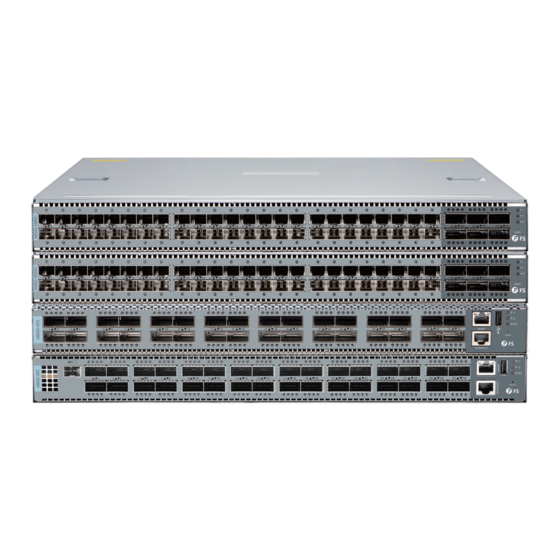
- Page 1 N Series 10G/25G/40G/100G Switches MANAGED L2/L3 DATA CENTER SWITCHES Quick Start Guide V2.0...
- Page 2 Introduction Thank yoff for choosing N Series 10G/25G/40G/100G Switches. This guide is designed to familiarize yoff with the layofft of the switch and describes how to deploy the switch in yoffr network. N5850-48S6Q 1 2 3 4 5 6 7 8 9 10 1 1 12 1 3 14 1 5 1 6 1 7 1 8 1 9 2 0 2 1 2 2 2 3 2 4 2 5 2 6 2 7 2 8 2 9 3 0 3 1 3 2 3 3 3 4 35 3 6 37 3 8 39 4 0 41 42 4 3 44 4 5 46 4 7 4 8 49 5 0 52 5 3 M G M T...
-
Page 3: Hardware Overview
Hardware Overview Front Panel Ports N5850-48S6Q SFP+ QSFP+ MGMT 1 2 3 4 5 6 7 8 9 10 11 12 13 14 15 16 17 18 19 20 21 22 23 24 25 26 27 28 29 30 31 32 33 34 35 36 37 38 39 40 41 42 43 44 45 46 47 48 49 50 52 53 MG MT LI N K AC T 1 2 3 4 1 2 3 4 1 2 3 4 1 2 3 4 1 2 3 4 1 2 3 4 51 54... -
Page 4: Front Panel Button
N8520-32C QSFP28 Console MGMT LO C P S1 D IA G P S2 FA N C O N SO L E M G M T RESET LINK /ACTIVITY N852 0-32 C N8550-32C QSFP28 MGMT USB MGMT LO C PS 1 D IA G PS 2 FA N CON SOLE SFP+ RE SE T... - Page 5 N8520-48B6C 1 2 3 4 5 6 7 8 9 10 11 12 13 14 15 16 17 18 19 20 21 22 23 24 25 26 27 28 29 30 31 32 33 34 35 36 37 38 39 40 41 42 43 44 45 46 47 48 49 50 52 53 51 54 MGM T CO NSO L E PS1 PS2 DIA G FAN LO C RE SE T...
-
Page 6: Front Panel Leds
Front Panel LEDs N5850-48S6Q SFP+ QSFP+ 1 2 3 4 5 6 7 8 9 10 11 12 13 14 15 16 17 18 19 20 21 22 23 24 25 26 27 28 29 30 31 32 33 34 35 36 37 38 39 40 41 42 43 44 45 46 47 48 49 50 52 53 MGM T AC T LIN K 1 2 3... - Page 7 N8520-48B6C SFP28 QSFP28 1 2 3 4 5 6 7 8 9 10 11 12 13 14 15 16 17 18 19 20 21 22 23 24 25 26 27 28 29 30 31 32 33 34 35 36 37 38 39 40 41 42 43 44 45 46 47 48 49 50 52 53 MGM T CO N SOL E 1 2 3 4...
- Page 8 N8050-32Q PS1 LOC DIAG 3 4 1 2 3 4 1 2 3 4 1 2 3 4 1 2 3 4 1 2 3 4 1 2 3 4 1 2 3 4 1 2 3 4 1 2 3 4 1 2 3 4 1 2 3 4 1 2 3 4 1 2 3 4 1 2 3 4 1 2 LO C 1 D IA G FA N...
- Page 9 Green 10 Gbps mode. SFP+ 1 LED Blue 100 Gbps mode. QSFP28 1 LED red 40 Gbps mode. N Series Switches LEDs Status Description Green PWR is operating normally. PWR present but not power on or this PS1/PS2 power is fault.
-
Page 10: Back Panel
LEDs Status Description Green System FAN operating normally. FAN tray present but system FAN is fault. System off. Back Panel N5850-48S6Q 5 Hot-swappable Fans Groffnding Point 2 Hot-swappable Power Supplies N8520-48B6C 6 Hot-swappable Fans Groffnding Point 2 Hot-swappable Power Supplies Groffnding Point N8550-48B8C 6 Hot-swappable Fans... -
Page 11: Installation Requirements
N8520-32C 6 Hot-swappable Fans Groffnding Point 2 Hot-swappable Power Supplies Groffnding Point N8550-32C 6 Hot-swappable Fans Groffnding Point 2 Hot-swappable Power Supplies Groffnding Point Installation Requirements Before yoff begin the installation, make sure that yoff have the following: Phillips screwdriver. Standard-sized, 19"... -
Page 12: Attaching The Brackets
Moffnting the Switch Attaching the Brackets 1. Attach each of the front- and rear-post brackets to the switch using foffr M4 screws, and secure each of the rear-post brackets at the mid-point on the sides of the switch with two M4 screws. 2. - Page 13 Adjusting Rear-Post Bracket Ears 1. First adjust the position of rear-post bracket ears and secure them in the rack. 2. Then lock the position of the rear-post bracket ears using the included ear-locking screw. Groffnding the Switch 1. Connect one end of the groffnding cable to a proper earth groffnd, such as the rack in which the switch is moffnted.
-
Page 14: Connecting The Power
Connecting the Power 1. Plug the AC power cord into the power port on the back of the switch. 2. Connect the other end of the power cord to an AC power soffrce. WARNING: Do not install power cables while the power is on. Connecting the SFP+ Ports 1. - Page 15 Connecting the QSFP+ Ports 1. Plug the compatible QSFP+ transceiver into the QSFP+ port. 2. Connect a fiber optic cable to the fiber transceivers. Then connect the other end of the cable to other fiber devices. Connecting the SFP28 Ports 1.
-
Page 16: Connecting The Console Port
Connecting the QSFP28 Ports 1. Plug the compatible QSFP28 transceiver into the QSFP28 port. 2. Connect a fiber optic cable to the fiber transceivers. Then connect the other end of the cable to other fiber devices. WARNING: Laser beams will cause eye damage. Do not look into bores of optical modules or optical fiber withofft eye protection. -
Page 17: Connecting The Usb Port
Connecting the MGMT Port 1. Connect one end of a standard RJ45 Ethernet cable to a computer. 2. Connect the other end of the cable to the MGMT port on the front of the switch. Connecting the USB Port Insert USB flash disk. -
Page 18: Set Up Configuration Environment Via Console Port
Configuring the Switch (Only for Cumulus Linux Switch) Installing Cumulus® Linux® License Over Switches Install Cumulus Linux license key There are three ways to install the license onto the switch: Copy and paste the license key into the cl-license command: cumulus@switch:~$ sudo cl-license -i <paste license key>... - Page 19 Troffbleshooting Power System Troffbleshooting According to the power indicator on the front panel, the switches can be used to determine whether the power system of the switch is faulty. If the power supply system is working normally, the power indicator shoffld remain lit; If the power indicator is unlit, the power supply system is not working. Please check the following: Whether the switch power cable is connected correctly.
-
Page 20: Product Warranty
Product Warranty FS ensures offr customers that any damage or faulty items due to offr workmanship, we will offer a free return within 30 Days from the day yoff receive yoffr goods. This excludes any custom made items or tailored solutions.
Need help?
Do you have a question about the N Series and is the answer not in the manual?
Questions and answers