
Related Manuals for FS N9510-64D


Summary of Contents for FS N9510-64D
- Page 1 N9510-64D L3 Data Center Switch L3 Rechenzentrums-Switch Switch L3 pour Centres de Données Quick Start Guide V1.0 Quick-Start Anleitung Guide de Démarrage Rapide...
- Page 2 Introduction Thank you for choosing N9510-64D switch. This guide is designed to familiarize you with the layout of the switch and describes how to deploy the switch in your network. SYS BMC PSU FAN ID 10F 13F 18F 21F 26F 29F...
-
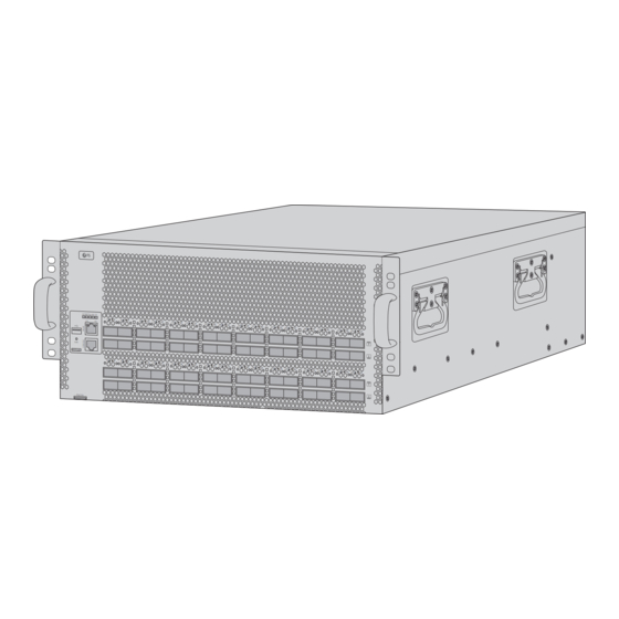
Page 3: Hardware Overview
SYS BMC PSU FAN ID 10F 13F 18F 21F 26F 29F 34F 37F 42F 45F 50F 53F 58F 61F Link FUNC N9510-64D 12F 15F 20F 23F 28F 31F 36F 39F 44F 47F 52F 55F 60F 63F ASSET TAG CONSOLE QSFPDD... - Page 4 LEDs State Description Off The system is powered off. Solid Red The system is malfunctional. Blinking Green The system is initializing. Solid Green The system is operational. Solid Yellow The system is abnormal. Off The BMC module is not-in-position or not working. Solid Green The BMC module works normally.
-
Page 5: Back Panel Ports
LEDs State Description Link Off The port is not connected. Solid Green The port is connected at 1000Mbps. LINK/ACT Solid Yellow The port is connected at 100Mbps. Act Off The port is not transmitting or receiving data. Act Blinking Green The port is transmitting or receiving data. - Page 6 Back Panel LEDs Power Supply Status Fan Status LEDs State Description Off The fan is powered off. Blinking Green The fan is initializing. Fan Status Solid Green The fan is operational. Solid Red The fan fails or stops. Off There is no power input or the power supply fails. Solid Green The power output is normal.
-
Page 7: Installation Requirements
Installation Requirements Before you begin the installation, make sure that you have the followings: Phillips screwdriver. Category 5e or higher RJ45 Ethernet cables, fiber optical cables and console cable for network devices. Site Environment: The operating temperature is 0°C-40°C, the humidity is 10%-90%. The installation site must be well ventilated. -
Page 8: Mounting The Switch
Mounting the Switch Rack Mounting 1. Secure the two L-shaped brackets to assemble a rack with eight M6 nuts. 2. Attach the switch to the rack and use four M6 screws to fix. -
Page 9: Replacing The Power Supply Module
Replacing the Power Supply Module 1. Press the power supply module and pull the handle of it slowly and straightly. 2. Hold the handle of the power module with one hand, and hold the bottom with the other hand. 3. Horizontally push the power module into the slot. The power module completely inserts in the slot until a “click”... -
Page 10: Replacing The Fan Module
Replacing the Fan Module 1. Push the handle of the fan module and pull out the fan module slowly. 2. Hold the handle of the fan module and insert it into the chassis slowly, ensure the fan module has a good contact with the slot until a “click” is heard. NOTE: 1. -
Page 11: Grounding The Switch
Grounding the Switch 1. Connect one end of the grounding cable to a proper earth ground, such as the rack in which the switch is mounted. 2. Connect the other end of the grounding cable on the switch back panel with the washers and screws. -
Page 12: Connecting The Console Port
Connecting the QSFPDD ports 1. Insert QSFPDD transceiver module into the switch. 2. Connect the fiber optic cable to the transceiver port, or directly connect DAC cable to the transceiver module Connecting the Console Port 1. Insert the RJ45 connector into the RJ45 CONSOLE port of the switch. 2. - Page 13 Connecting the MGMT Port 1. Connect one end of a standard RJ45Ethernet cable to a computer. 2. Connect the other end of the cable to the MGMT port of the switch. Connecting the USB Port Insert the Universal Serial Bus(USB) flash disk to the USB port for software and configuration backup and offline software upgrade.
-
Page 14: Configuring The Switch
Configuring the Switch Configuring the Switch Using the Console Port Step1: Connect a computer to the console port of the switch using the console cable. Step2: Start the terminal simulation software such as HyperTerminal on the computer. Step3: Set the parameters of the HyperTerminal:115200 bits per second, 8 data bits, no parity, 1 stop bit and no flow control. -
Page 15: Online Resources
Contact Us https://www.fs.com/contact_us.html Product Warranty Warranty: N9510-64D switch enjoys 5 years limited warranty against defects in materials or workmanship. For more details about warranty, please check at https://www.fs.com/policies/warranty.html Return: If you want to return item(s), information on how to return can be found at... - Page 16 Einführung Vielen Dank, dass Sie sich für den Switch N9510-64D entschieden haben. Diese Anleitung soll Sie mit dem Aufbau des Switches vertraut machen und beschreibt, wie Sie den Switch in Ihrem Netzwerk einsetzen. SYS BMC PSU FAN ID 10F 13F...
- Page 17 SYS BMC PSU FAN ID 10F 13F 18F 21F 26F 29F 34F 37F 42F 45F 50F 53F 58F 61F Link FUNC N9510-64D 12F 15F 20F 23F 28F 31F 36F 39F 44F 47F 52F 55F 60F 63F ASSET TAG CONSOLE QSFPDD...
- Page 18 Status Beschreibung Das System ist ausgeschaltet. Durchgehend Rot Das System funktioniert nicht. Blinkt Grün Das System wird initialisiert. Durchgehend Grün Das System ist betriebsbereit. Durchgehend Gelb Das System ist fehlerhaft. Das BMC-Modul ist nicht an seinem Platz oder funktioniert nicht. Durchgehend Grün Das BMC-Modul funktioniert normal.
- Page 19 Status Beschreibung Verbindung aus Der Port ist nicht verbunden. Durchgehend Grün Der Port ist mit 1000Mbps angeschlossen. LINK/ACT Durchgehend Gelb Der Port ist mit 100Mbps verbunden. Act Aus Der Port sendet oder empfängt keine Daten. Act Blinkt Grün Der Port sendet oder empfängt gerade Daten. Der Port ist nicht verbunden.
- Page 20 LEDs an der Rückseite Stromversorgungsstatus Lüfter-Status Status Beschreibung Der Lüfter ist ausgeschaltet. Blinkt Grün Der Lüfter wird initialisiert. Lüfter Status Durchgehend Grün Der Lüfter ist betriebsbereit. Durchgehend Rot Der Lüfter fällt aus oder stoppt. Es gibt keine Stromzufuhr oder die Stromversorgung fällt aus.
- Page 21 Installationsvoraussetzungen Bevor Sie mit der Installation beginnen, vergewissern Sie sich, dass Sie über die folgenden Dinge verfügen: Kreuzschlitzschraubendreher. RJ45-Ethernet-Kabel der Kategorie 5e oder höher, Glasfaserkabel und Console-Kabel für Netzwerkgeräte. Standortumgebung: Die Betriebstemperatur liegt bei 0°C-40°C, die Luftfeuchtigkeit bei 10%-90%. Der Installationsort muss gut belüftet sein. Stellen Sie sicher, dass um den Switch herum ein ausreichender Luftstrom vorhanden ist.
-
Page 22: Montage Des Switches
Montage des Switches Rack-Montage 1. Befestigen Sie die beiden L-förmigen Halterungen mit acht M6-Muttern, um ein Rack zu montieren. 2. Bringen Sie den Switch am Rack an und befestigen Sie ihn mit vier M6-Schrauben. - Page 23 Auswechseln des Stromversorgungsmoduls 1. Drücken Sie auf das Stromversorgungsmodul und ziehen Sie langsam und gerade am Griff. 2. Halten Sie den Griff des Stromversorgungsmoduls mit einer Hand fest, und halten Sie die Unterseite mit der anderen Hand. 3. Schieben Sie das Stromversorgungsmodul waagerecht in den Steckplatz. Das Stromversorgungsmodul wird vollständig in den Steckplatz eingeführt, bis ein "Klick"...
- Page 24 Auswechseln des Lüftermoduls 1. Drücken Sie den Griff des Lüftermoduls und ziehen Sie das Lüftermodul langsam heraus. 2. Halten Sie den Griff des Lüftermoduls und setzen Sie es langsam in das Gehäuse ein. Achten Sie darauf, dass das Lüftermodul einen guten Kontakt mit dem Steckplatz hat, bis ein "Klick" zu hören ist.
-
Page 25: Anschließen Der Stromversorgung
Erdung des Switches 1. Schließen Sie ein Ende des Erdungskabels an eine geeignete Erdung an, z.B. an das Rack, in dem der Switch montiert ist. 2. Schließen Sie das andere Ende des Erdungskabels mit den Unterlegscheiben und Schrauben an der Rückwand des Switches an. Anschließen der Stromversorgung 1. - Page 26 Anschließen der QSFPDD-Ports 1. Setzen Sie das QSFPDD-Transceivermodul in den Switch ein. 2. Schließen Sie das Glasfaserkabel an den Transceiver-Port an, oder verbinden Sie das DAC-Kabel direkt mit dem Transceiver-Modul. Anschließen des Console-Ports 1. Stecken Sie den RJ45-Stecker in den RJ45 Console-Port des Switches. 2.
- Page 27 Anschließen des MGMT-Ports 1. Schließen Sie ein Ende eines standardmäßigen RJ45-Ethernet-Kabels an einen Computer an. 2. Schließen Sie das andere Ende des Kabels an den MGMT-Port des Switches an. Anschließen des USB-Ports Stecken Sie die USB-Flash-Disk (Universal Serial Bus) in den USB-Port ein, um Software und Konfiguration zu sichern und die Software offline zu aktualisieren.
-
Page 28: Fehlersuche
Konfigurieren des Switches Konfigurieren des Switches über den Console-Port Schritt 1: Schließen Sie einen Computer über das Console-Kabel an den Console-Port des Switches an. Schritt 2: Starten Sie die Terminalsimulationssoftware wie HyperTerminal auf dem Computer. Schritt 3: Stellen Sie die Parameter von HyperTerminal ein: 115200 Bits pro Sekunde, 8 Datenbits, keine Parität, 1 Stoppbit und keine Flusskontrolle. - Page 29 Kontakt https://www.fs.com/de/contact_us.html Produktgarantie Garantie: Für den Switch N9510-64D gilt eine beschränkte Garantie von 5 Jahren auf Material- und Verarbeitungsfehler. Weitere Einzelheiten zur Garantie finden Sie unter https://www.fs.com/de/policies/warranty.html Rückgabe: Wenn Sie einen oder mehrere Artikel zurückgeben möchten, finden Sie Informationen zur Rückgabe unter...
- Page 30 Introduction Nous vous remercions d'avoir choisi le switch N9510-64D. Ce guide est conçu pour que vous puissiez vous familiariser avec la configuration du switch et décrit comment procéder à son déploiement. SYS BMC PSU FAN ID 10F 13F 18F 21F...
-
Page 31: Aperçu Du Matériel
SYS BMC PSU FAN ID 10F 13F 18F 21F 26F 29F 34F 37F 42F 45F 50F 53F 58F 61F Link FUNC N9510-64D 12F 15F 20F 23F 28F 31F 36F 39F 44F 47F 52F 55F 60F 63F ASSET TAG CONSOLE QSFPDD... - Page 32 Statut Description Éteint Le système est hors tension. Rouge Le système ne fonctionne pas correctement. Vert Clignotant Le système est en cours d'initialisation. Vert Le système est opérationnel. Jaune Le système présente une anomalie. Éteint Le module BMC n'est pas en place ou ne fonctionne pas. Vert Le module BMC fonctionne normalement Vert Clignotant...
-
Page 33: Ports Du Panneau Arrière
Statut Description Link Éteint Le port n'est pas relié. Vert Le port est connecté à 1000Mbps. LINK/ACT Jaune Le port est connecté à 100Mbps. Act Éteint Le port ne transmet pas ou ne reçoit pas de données. Act Vert Clignotant Le port transmet ou reçoit des données. - Page 34 Indicateurs LED du Panneau Arrière Statut de l'Alimentation Électrique Statut du Ventilateur Statut Description Éteint Le ventilateur est éteint. Vert Clignotant Le ventilateur est en cours d'initialisation. Fan Status Vert Le ventilateur est opérationnel. Rouge Le ventilateur est en panne ou ne fonctionne pas. Il n'y a pas d'entrée de courant ou l'alimentation Éteint électrique est défaillante.
-
Page 35: Exigences D'installation
Exigences d'Installation Avant de commencer l'installation, assurez-vous que vous disposez des éléments suivants : Tournevis phillips. Câbles Ethernet RJ45 cat5e ou supérieure, câbles à fibre optique et câble de console pour les périphériques réseau. Site de l'Installation : La température de fonctionnement est de 0°C-40°C, l'humidité est de 10%-90%. Le site d'installation doit être bien ventilé. -
Page 36: Montage En Rack
Installation du Switch Montage en Rack 1. Fixez les deux supports en L pour assembler un rack avec huit écrous M6. 2. Fixez le switch au rack. Utilisez quatre vis M6 pour le fixer. - Page 37 Remplacement du Module d'Alimentation 1. Appuyez sur le module d'alimentation et tirez la poignée lentement et en ligne droite. 2. Tenez la poignée du module d'alimentation d'une main, et soutenez le dessous avec l'autre main. 3. Poussez horizontalement le module d'alimentation dans l'emplacement. Le module d'alimentation s'insère complètement dans la fente jusqu'à...
- Page 38 Remplacement du Module de Ventilation 1. Poussez la poignée du module du ventilateur et retirez lentement le module. 2. Tenez la poignée du module de ventilation et insérez-le lentement dans le châssis. Le module de ventilation est correctement installé dans le logement lorsqu'un "clic" est entendu. NOTE : 1.
-
Page 39: Connexion De L'alimentation
Mise à la Terre du Switch 1. Connectez une extrémité du câble de mise à la terre à une mise à la terre appropriée, telle que le rack dans lequel le switch est monté. 2. Connectez l'autre extrémité du câble de mise à la terre sur le panneau arrière du switch avec les rondelles et les vis. - Page 40 Connexion aux Ports QSFPDD 1. Insérez le module QSFPDD dans le port. 2. Connectez le câble à fibre optique au port du module, ou connectez directement le câble DAC au module. Connexion du Port Console 1. Insérez le connecteur RJ45 dans le port RJ45 CONSOLE du switch. 2.
- Page 41 Connexion du Port MGMT 1. Connectez une extrémité d'un câble RJ45Ethernet standard à un ordinateur. 2. Connectez l'autre extrémité du câble au port MGMT du swich. Connexion du Port USB Insérez le dispositif USB (Universal Serial Bus) dans le port USB pour la sauvegarde du logiciel et de la configuration et la mise à...
-
Page 42: Dépannage
Configuration du Switch Configuration du Switch à l'Aide du Port Console Étape 1 : Connectez un ordinateur au port de console du switch à l'aide du câble de console. Étape 2 : Démarrez le logiciel HyperTerminal sur l'ordinateur. Étape 3 : Définissez les paramètres de l'HyperTerminal : 115200 bits par seconde, 8 bits de données, pas de parité, 1 bit d'arrêt et pas de contrôle de flux. -
Page 43: Garantie Du Produit
Contactez-Nous https://www.fs.com/fr/contact_us.html Garantie du Produit Garantie : Le switch N9510-64D bénéficie d'une garantie limitée de 5 ans contre les défauts matériels ou de fabrication. Pour plus de détails sur la garantie, veuillez consulter la page https://www.fs.com/fr/policies/warranty.html Retour : Si vous souhaitez retourner un ou plusieurs articles, vous trouverez des informations sur la procédure de retour à... -
Page 44: Compliance Information
Any changes or modifications not expressly approved by the grantee of this device could void the user's authority to operate the equipment. Responsible party (only for FCC matter) FS.COM Inc. 380 Centerpoint Blvd, New Castle, DE 19720, United States https://www.fs.com... - Page 45 2014/35/EU konform ist. Eine Kopie der EU-Konformitätserklärung finden Sie unter www.fs.com/de/company/quality_control.html FS.COM GmbH déclare par la présente que cet appareil est conforme à la Directive 2014/30/UE et 2014/35/UE. Une copie de la Déclaration UE de Conformité est disponible sur https://www.fs.com/fr/company/quality_control.html FS.COM LIMITED...
Need help?
Do you have a question about the N9510-64D and is the answer not in the manual?
Questions and answers