
Related Manuals for FS NC8400 Series


Summary of Contents for FS NC8400 Series
- Page 1 NC8400 Series Switch 4-SLOT 4U L3 DATA CENTER SWITCH CHASSIS AND LINE CARD Quick Start Guide V1.0...
- Page 2 Introduction Thank you for choosing NC8400-4TH switch chassis and NC8400-32C line card. This guide is designed to familiarize you with the layout of the switch and describes how to deploy the switch in your network. NC8400-4TH NC8400-32C ASSET TAG NC8400-4TH Accessories Power Cord x4 Grounding Cable x1...
-
Page 3: Hardware Overview
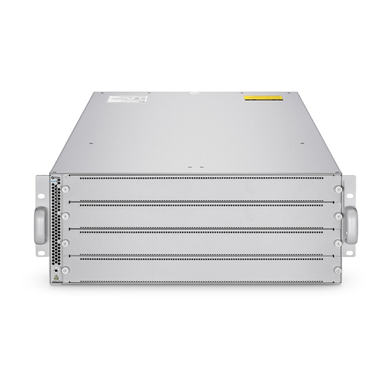
Hardware Overview Switch Chassis Front Panel NC8400-4TH NC8400-4TH Blank Plate ASSET TAG ASSET TAG Parts Description Install a blank panel to the empty slot to prevent dust from entering Blank Plate the switch. Asset management label ASSET TAG Front Panel Port NC8400-4TH NC8400-4TH ASSET TAG... -
Page 4: Back Panel Ports
Back Panel NC8400-4TH AFM-NC4TH-FB AFM-NC4TH-FB AFM-NC4TH-FB Status Status Status NC8400-4TH PWR1 FAN1 FAN3 FAN5 PWR2 Power Supplies AFM-NC4TH-FB AFM-NC4TH-FB AFM-NC4TH-FB Status Status Status MGMT PWR3 Link FAN2 FAN4 FAN6 Console Grounding Point PWR4 ASSET TAG Fan Slots ASSET TAG Back Panel Ports NC8400-4TH AFM-NC4TH-FB AFM-NC4TH-FB... -
Page 5: Back Panel Leds
Back Panel LEDs NC8400-4TH Fan Status AFM-NC4TH-FB AFM-NC4TH-FB AFM-NC4TH-FB Status Status Status NC8400-4TH PWR1 FAN1 FAN3 FAN5 PWR2 Power AFM-NC4TH-FB AFM-NC4TH-FB AFM-NC4TH-FB Link/ACT Supply Status Status Status MGMT PWR3 Link Status FAN2 FAN4 FAN6 Console PWR4 ASSET TAG LEDs Status Description The system is powered o . - Page 6 LEDs Status Description The system is powered o . Blinking Green The fan is initializing. Solid Green The fan is operational. Solid Yellow One of the fans is not in the position. 1. One of the fan modules fails. Solid Red 2.
- Page 7 LEDs Status Description There is no power input or the power supply fails. Solid Green The power input is normal. Solid Red An error occurs, e.g., overcurrent, overvoltage or fan fault. Power Supply Status Solid Yellow The AC power in redundancy is plugged out. An alarm is generated but the power module keeps working.
- Page 8 Line Cards Front Panel Ports NC8400-32C QSFP28 Status NC8400-32C Ports Description QSFP28 QSFP28 ports for 40/100G connection Front Panel LEDs NC8400-32C Status QSFP28 Status NC8400-32C LEDs Status Description The line card is powered o . Solid Red The line card fails or resets. Blinking Green The line card is initializing.
-
Page 9: Installation Requirements
Installation Requirements Before you begin the installation, make sure that you have the following: Phillips screwdriver. Standard-sized, 19" wide rack with a minimum of 4U height available. Category 5e or higher RJ45 Ethernet cables, ber optical cables and console cable for connecting network devices. -
Page 10: Mounting The Switch
Mounting the Switch Rack Mounting 1. Attach the guide rails to the rack using eight M6*16 screws and nuts. 2. Attach the switch to the rack using four M6*16 screws and nuts. The switch chassis stops on the guide rails. - Page 11 Installing the Vertical Cable Managers 1. The four M6*16 screws and nuts on the mounting brackets should be removed before installing the vertical cable managers. 2. Remove the handles on the mounting brackets. NC 84 00 -4T 3. Attach the vertical cable managers to the rack using four M6*25 screws and nuts.
-
Page 12: Installing The Line Cards
Installing the Line Cards NC 84 00 -4T 1. Pinch the captive screws on line card and rotate the ejector lever outward. Push the line card into the slot horizontally. 2. Tighten the captive screws with a screwdriver to secure line card in the chassis. NOTE: Line card NC8400-32C is hot-swappable. -
Page 13: Replacing The Power Supply Module
Replacing the Power Supply Module ol e Co ns 1. Press and hold the lock of the power module leftward and pull the module out by the handle. ol e Co ns 2. Take the plane printed with power information as the top panel of the power module. Hold the handle of the power module with one hand, and support the bottom with the other hand. -
Page 14: Replacing The Fan Module
Replacing the Fan Module N I- F M 2 E FA ol e Co ns 1. Loosen the captive screws of the fan module with a screwdriver. 2. Hold the handle at the end of the fan module, and withdraw the fan module slowly. ol e Co ns A N I- F... -
Page 15: Grounding The Switch
Grounding the Switch C on so 1. Connect one end of the grounding cable to a proper earth ground, such as the rack in which the switch is mounted. 2. Secure the grounding lug to the grounding point on the switch back panel with the washers and screw. -
Page 16: Connecting The Console Port
Connecting the QSFP28 Ports NC 84 00 -4 TH First install QSFP28 transceivers and then connect ber optic cables to the transceiver ports, or directly connect DAC cables to the QSFP28 slots. WARNING: Laser beams will cause eye damage. Do not look into bores of transceivers or optical bers without eye protection. -
Page 17: Connecting The Usb Port
Connecting the MGMT Port ol e Co ns 1. Connect one end of a standard RJ45 Ethernet cable to a computer. 2. Connect the other end of the cable to the MGMT port on the rear of the switch. Connecting the USB Port ol e Co ns Insert the Universal Serial Bus (USB) ash disk to the USB port for software and con guration backup... - Page 18 Con guring the Switch Con guring the Switch Using the Console Port: Step 1: Connect a computer to the console port of the switch using the console cable. Step 2: Start the terminal simulation software such as HyperTerminal on the computer. Step 3: Set the parameters of the HyperTerminal: 115200 bits per second, 8 data bits, no parity, 1 stop bit and no ow control.
-
Page 19: Troubleshooting
Troubleshooting Power System Fault The indicator on the front panel of the host is OFF. The Status indicator of the fan module is OFF, and the fan does not work. The indicator of the power module is OFF. Please check the following: First disconnect the power cord of the power module. -
Page 20: Support And Other Resources
Product Warranty FS ensures our customers that any damage or faulty items due to our workmanship, we will o er a free return within 30 Days from the day you receive your goods. This excludes any custom made items or tailored solutions.
Need help?
Do you have a question about the NC8400 Series and is the answer not in the manual?
Questions and answers