Advertisement
Quick Links
Advertisement

Related Manuals for FS N9600 Series


Summary of Contents for FS N9600 Series
- Page 1 N9600 SERIES DATA CENTER SWITCHES Quick Start Guide V1.0...
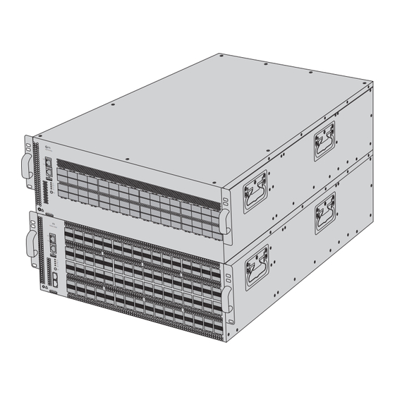
- Page 2 Introduction Thank you for choosing the N9600 Series Data Center Switches. This guide is designed to familiarize you with the layout of the switches and describe how to deploy them in your network. N9600-64OD MGMT Link Console ASSET TAG N9600-64OD...
- Page 3 Accessories Power Cord x4 Grounding Cable x1 #10-32UNF Cage Nut x12 #10-32UNF Screw x12 Guide Rail x2 NOTE: The accessories may vary from illustration, please prevail in kind. Hardware Overview Front Panel Ports N9600-64OD OSFP N9600-64OD MGMT MGMT Link Console CONSOLE ASSET TAG...
- Page 4 A USB management port for software and con guration backup and o ine software upgrade NOTE: For information on LEDs and buttons, check the PicOS manual or FS documents online, or ask the technical support personnel for help. Installation Requirements...
- Page 5 Site Environment: The operating temperature should not exceed 45°C. The installation site should be well-ventilated to ensure su cient air ow around the switch. The installation site should be free of dust, leaks, drips, heavy condensation, and moisture. Make sure that the rack is properly grounded. To facilitate heat dissipation and maintenance, avoid installing the equipment against the wall, and make sure that there is adequate space around its four sides.
- Page 6 2. Slowly push the switch until the mounting brackets align with the #10-32UNF cage nuts, then secure the switch to the rack using the #10-32UNF screws. Grounding the Switch 1. Connect one end of the grounding cable to a proper earth ground, such as the rack in which the switch is mounted.
- Page 7 Connecting the OSFP Ports N 9 6 0 0 -6 4 M G M A C T Li n k C o n so S Y S B M C P S U F A N U ID A S S E T T A 1.
- Page 8 Connecting the CONSOLE Port 1. Connect the RJ45 end of a console cable to the CONSOLE port of the switch. 2. Connect the DB9 end of the console cable to the serial port of a computer. Connecting the MGMT Port 1.
- Page 9 Connecting the USB Port Insert a Universal Serial Bus (USB) ash disk into the USB port of the switch. Connecting the Power 1. Plug the power cord into the power port on the back of the switch. 2. Connect the other end of the power cord to an AC power source.
- Page 10 Troubleshooting The System Login Password Is Lost Please contact the FS technical support personnel for help. The Power Module Does Not Supply Power Disconnect the power cord of the power module and check the following: 1. Check whether the cable connections of the rack are correct.
- Page 11 Product Warranty FS ensures our customers that for any damage or faulty items due to our workmanship, we will o er a free return within 30 days from the day you receive your goods. This excludes any custom-made items or tailored solutions.
Need help?
Do you have a question about the N9600 Series and is the answer not in the manual?
Questions and answers