
Related Manuals for FS N5860-48SC


Summary of Contents for FS N5860-48SC
- Page 1 N5860-48SC Switch Hardware Installation and Maintenance Guide V1.0.2306A Innovation · Expertise · Agility...
- Page 2 Safety Statement: • To avoid harm to people and equipment, please read the safety recommendations in the Safety Precautions for FS Switches before installing the FS Switch. Verify that the requirements described in the Safety Precautions for FS •...
-
Page 3: Table Of Contents
Contents 1. Hardware Installation and Parts Replacement 1.1 Installation Procedure 1.2 Installation Preparation 1.3 Installing a Switch 1.4 Installing Modules 1.5 Connecting a Switch 1.6 Post-Installation Checks 1.7 System Commissioning 1.8 Parts Replacement 2. Troubleshooting After Installatio 2.1 Troubleshooting Flowchart 2.2 Guide to Using Switches 2.3 Guide to Using Optical Modules Innovation ·... -
Page 4: Hardware Installation And Parts Replacement
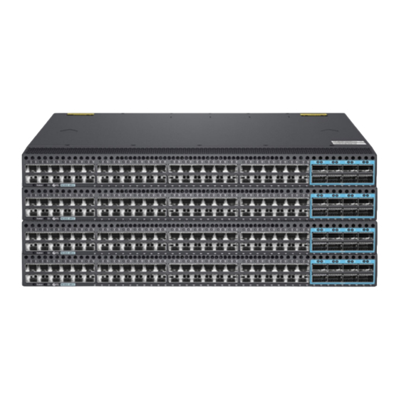
Hardware Installation and Parts Replacement The N5860-48SC is a new generation of high-density 10G ports access switch developed by FS.com for data centers, supporting low latency and complete data center features. 48 10G ports and 8 100G ports are available on a single N5860-48SC switch. -
Page 5: Installation Procedure
Confirm that the "Installation Precautions" requirements described in Chapter 2 have been met. • 1.2.2 Checking the Installation Site The N5860-48SC switch must be used indoors. To ensure normal operations and long service life of the device , the installation site must meet the following requirements. Innovation · Expertise · Agility... - Page 6 Hardware Installation and Parts Replacem Switch Hardware Installation and Maintenance Guide Requirement Item The device must be installed in a clean, dry, and well ventilated standard equipment room with controllable Cleanliness temperature. Dustproof measures must be taken in the site. Dust will cause electrostatic discharges on the chassis and Dust proofing affect connections of metal connectors and joints.
- Page 7 Dust-free paper and fiber end-face microscope Meters Multimeter, bit error rate tester (BERT), and optical power meter • The N5860-48SC switch is delivered without a tool kit. You need to prepare a tool kit by yourself. Innovation · Expertise · Agility...
-
Page 8: Installing A Switch
Precautions: Before installing the N5860-48SC switch in a cabinet, please check whether the racks are properly positioned. If the racks are too close to the front door of the cabinet, you may not be able to close the front door after plugging in the Ethernet and fiber cables . - Page 9 Hardware Installation and Parts Replacem Switch Hardware Installation and Maintenance Guide • Install a mounting bracket by driving four screws into the four among the six screw holes on each side of the panel. • Distinguish left and right rack-mount guides according to the marked orientation.
-
Page 10: Installing Modules
Hardware Installation and Parts Replacem Switch Hardware Installation and Maintenance Guide 1.4 Installing Modules • Wear an anti-static wrist strap before the following operations. 1.4.1 Installing Fan Modules Take a fan module from its packing materials. 2. Grasp the handle and slide the module into the slot along the guide rail until you feel the connector snap into place. - Page 11 Hardware Installation and Parts Replacem Switch Hardware Installation and Maintenance Guide Slide the fan module into the slot. Verify that the fan module is in the correct orientation. • • If you find it difficult to fully insert the fan module, pull the fan module out, and slide it into the slot again.
- Page 12 Hardware Installation and Parts Replacem Switch Hardware Installation and Maintenance Guide 1.4.2.1 Power Module Features Features Description Use of "Three-proof Paint" With moisture-proof, anti-salt spray, anti-mold, insulation, anti-leakage and other functions Input under-voltage protection, output over-current protection, output over- Protective Function voltage protection, output short-circuit protection and other functions.
-
Page 13: Connecting A Switch
Hardware Installation and Parts Replacem Switch Hardware Installation and Maintenance Guide • When inserting an optical module to a port, hold the optical module horizontally. If the optical module cannot be completely inserted into the optical port, do not force it into the port. Turn the optical module 180 degrees over and try again. - Page 14 Switch Hardware Installation and Maintenance Guide There is one ground terminal on the back of the N5860-48SC switch chassis, which should be connected to the groun din g lug of the rack first, and then connect the grounding lug to the grounding bar of the equipment room.
- Page 15 Hardware Installation and Parts Replacement Switch Hardware Installation and Maintenance Guide - Perform the following steps to connect the AC power cable: Insert the plug of the AC power cable into the power socket in the AC power module. Figure 7: Connect the AC Power Cable 2.
- Page 16 Hardware Installation and Parts Replacem Switch Hardware Installation and Maintenance Guide 1.5.3 Connecting Ethernet Cables Connect the RJ45 connector of an Ethernet cable to the management port on the equipment, and the other end to a network management switch or terminal. 1.5.4 Connecting Optical Fibers According to the identification on the panel of the card, insert the single-mode or multi-mode fiber into the corresponding interface, and pay attention to the distinction between the sender and receiver of the fiber...
- Page 17 Hardware Installation and Parts Replacement Switch Hardware Installation and Maintenance Guide Figure 9: Connecting a High-speed Cable To remove a high-speed cable, gently push the cable connector and then pull the handle of the connector. Do not directly pull the cable connector with force. See Figure 9. Figure 10: Removing a High-speed Cable 6.
-
Page 18: Post-Installation Checks
Hardware Installation and Parts Replacement Switch Hardware Installation and Maintenance Guide 1.5.6 Connecting the Console Port Connection Steps: Connect the RJ45 connector of an Ethernet cable to the console port of the switch, and connect the DB9 connector to a network management switch or terminal. •... -
Page 19: System Commissioning
Hardware Installation and Parts Replacem Switch Hardware Installation and Maintenance Guide 1.7 System Commissioning 1.7.1 Setting Up the Configuration Environment Connect the PC to the console port of the switch through the Ethernet cable, as shown in the figure below. Figure 11: Configuration Environment 1.7.2 Connection Cables... - Page 20 Hardware Installation and Parts Replacem Switch Hardware Installation and Maintenance Guide Step 3: Start Terminal Emulation Software on the Computer (Such as PUTTY) Step 4: Setting Terminal Parameters Parameter requirements: Baud rate is 9600, connection type is Serial, fill in COM port number according to the actual situation. The specific diagram is as follows.
-
Page 21: Parts Replacement
Hardware Installation and Parts Replacement Switch Hardware Installation and Maintenance Guide 1.8 Parts Replacement 1.8.1 Removing a Power Module and Fan Module Removing a Fan Module: Loosen the captive screws of the fan module. 2. Grasp the handle and pull the fan module out of the slot gently. 3. - Page 22 Hardware Installation and Parts Replacement Switch Hardware Installation and Maintenance Guide Pull the fan module out of the slot gently. • • Install a filler panel in the unoccupied slot to ensure adequate airflow and avoid dust in the chassis. Removing a Power Module: Press the latch on the module and grasp the handle with one hand.
- Page 23 Hardware Installation and Parts Replacem Switch Hardware Installation and Maintenance Guide • The GW-CRPS550N2C power supply module should be pulled out in such a way as to ensure that the power supply module is pulled out straight and slowly. • If the power module is no longer installed in the location where the power module was removed, the power slot empty baffle plate needs to be installed to ensure proper ventilation and heat dissipation in the chassis to avoid dust.
- Page 24 Hardware Installation and Parts Replacement Switch Hardware Installation and Maintenance Guide Two types of latches on fiber optic connectors: • LC/PC connector, opened by pressing the buckle, as shown in Figure 14. • MPO connector, opening automatically when the buckle is pulled, as shown in Figure 15. Figure 15: LC/PC Connector Figure 16:...
- Page 25 Hardware Installation and Parts Replacement Switch Hardware Installation and Maintenance Guide Figure 18: Handle-type Handle 5. Take out the new optical module from the package, and slowly insert it into the interface until you hear a "pop" sound, indicating that it has been installed in place. 6.
- Page 26 Hardware Installation and Parts Replacem Switch Hardware Installation and Maintenance Guide 2. Check whether the business is ready for power-off, and save relevant business information. 3. Disconnect the power cord and ground wire of the faulty device. 4. Pull out all the network cables and optical fibers of the faulty device. 5.
-
Page 27: Troubleshooting After Installation
Troubleshooting After Installation Innovation · Expertise · Agility... -
Page 28: Troubleshooting Flowchart
Check the connector of power supply module each module Check the installation of Check the LEDs on the device other modules Check serial port connection Check the cable connection and parameters Contact FS Technical Support Innovation · Expertise · Agility... -
Page 29: Guide To Using Switches
Fault Symptom The system login password of the switch is forgotten or lost, and the data cannot be configured. Handling Method Please contact FS technical support. Fault 2: The AC power module does not work Fault Symptom All LEDs on the front panel are off. The fan status LED is off, and the fan does not rotate. The power supply status LED is off. - Page 30 Sometimes glitches can appear on these hardware. 5. Contact Vendor Support: If there is still no output on the serial port, please contact FS technical support. Fault 5: The serial port console output is garbled Fault Symptom The serial port console output is garbled.
-
Page 31: Guide To Using Optical Modules
Troubleshooting After Installation Switch Hardware Installation and Maintenance Guide Check whether the receive and transmit ends are reversed. The transmit end of an optical port must be connected to the receive end at the other end. You can confirm both ends by exchanging the connection order of two fiber cables. - Page 32 Troubleshooting After Installation Switch Hardware Installation and Maintenance Guide If the latch boss is not secured, the gold finger of the optical module is not in good contact with the connector on the board. In this case, the link may be connected but optical signals will be cut off or the optical module will be loosened when the optical module is shaken or hit.
- Page 33 Troubleshooting After Installation Switch Hardware Installation and Maintenance Guide Place at least three cleaning tissues on the work bench. As shown in Figure 19, wipe the end of an • optical connector from left to right or from right to left on a cleaning tissue, and then move the connector end to the unused part of the cleaning tissue to continue.
- Page 34 Troubleshooting After Installation Switch Hardware Installation and Maintenance Guide Figure 23: Installing a Protective Cap on a Fiber 4. If a receptacle or an optical connector has not been used for a long time and is not covered with a protective cap, you need to clean it before using it.
- Page 35 Troubleshooting After Installation Switch Hardware Installation and Maintenance Guide Before using an optical time-domain reflectometer (OTDR) to test the connectivity or the attenuation of optical signals, disconnect the optical fibers from the optical module. Otherwise, the optical module will be burnt. 2.
- Page 36 FS has invested resources in product R&D, quality control, intelligent manufacturing, industry-leading experts, professional technical support, and networking solutions. All is to provide customers with higher-performance, lower-power consumption, and the most cost-effective products, promoting clients' network upgrades. For more information and technical support, welcome to contact us at www.fs.com/contact_us.html...
Need help?
Do you have a question about the N5860-48SC and is the answer not in the manual?
Questions and answers