Sign In
Upload
Download
Table of Contents
Contents
Add to my manuals
Delete from my manuals
Share
URL of this page:
HTML Link:
Bookmark this page
Add
Manual will be automatically added to "My Manuals"
Print this page
×
Bookmark added
×
Added to my manuals
Manuals
Brands
FS Manuals
Switch
N Series
User manual
FS N Series User Manual
Hide thumbs
Also See for N Series
:
Quick start manual
(21 pages)
,
Quick start manual
(21 pages)
1
2
Table Of Contents
3
4
5
6
7
8
9
10
11
12
13
14
15
16
17
18
19
20
21
22
23
24
page
of
24
Go
/
24
Contents
Table of Contents
Bookmarks
Table of Contents
Table of Contents
Chapter 1 Ethernet Switches Introduction
Overview
Chapter 2 Product Characteristics
Layer Two Hardware Supported
Layer Three Hardware Supported
Traffic Management
Power and Cooling
Environmental: Operating
Approvals
Chapter 3 Description of Hardware
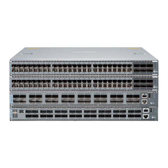
Port Diagram
Console Description
Status Leds
Chapter 4 Link Graph
Spine-And-Leaf Architecture
Applications of Connection for N Series Switches with Transceivers and Fiber
Enclosures
Connection for FS N8500-32C 100G Switch with 100G QSFP28 SR4 Transceivers
Direct Connection with Optical Transceivers
Migrate to 40Gbe by Interconnecting LC Duplex Cables and MTP Trunk Cable
Chapter 5 Introduction to Installation Accessories
Chapter 6 Installation
Installation Preparation
Verify the Package Contents
Required Tools and Utilities
Device Installation
Installing the Switch
Installing the Power Supply Module
Installing the Fan
Connecting Console
QSFP+ Transceiver Installation
Copper Cable/Fiber Cable Connection
AC Power Supply Connection
Earthing Cable Connection
Checking the Switch
Advertisement
Quick Links
1
Overview
2
Chapter 1 Ethernet Switches Introduction
3
Console Description
4
Connecting Console
5
Checking the Switch
Download this manual
N-Series Ethernet
Switches User Manual
FS
Table of
Contents
Previous
Page
Next
Page
1
2
3
4
5
Advertisement
Table of Contents
Need help?
Do you have a question about the N Series and is the answer not in the manual?
Ask a question
Questions and answers
Related Manuals for FS N Series
Switch FS N Series Quick Start Manual
Managedl2/l3data center switches (21 pages)
Switch FS N Series Quick Start Manual
Managed l2/l3 data center 10g/25g/40g/100g switches (21 pages)
Switch FS N8500-32C User Manual
(24 pages)
Switch FS N5860 Series Quick Start Manual
10g/25g/100g l3 data center switches (25 pages)
Switch FS N5860 Series Configuration Manual
(7 pages)
Switch FS N5860-48SC Hardware Installation And Maintenance Manual
(36 pages)
Switch FS N8560-48BC Quick Start Manual
10g/25g/100g l3 data center switches (25 pages)
Switch FS N8560-32C Quick Start Manual
L3 data center switch (62 pages)
Switch FS N8560-64C Quick Start Manual
10g/25g/100g l3 data center switches (25 pages)
Switch FS NC8200 Series Quick Start Manual
4-slot 2u l3 data center switch chassis and line cards (20 pages)
Switch FS NC8400 Series Quick Start Manual
4-slot 4u l3 data center switch chassis and line card (21 pages)
Switch FS N9510-64D Quick Start Manual
L3 data center switch (46 pages)
Switch FS N9550-64D Quick Start Manual
Data center switch (46 pages)
Switch FS N8550-24CD8D Quick Start Manual
Data center switch (44 pages)
Switch FS N9600 Series Quick Start Manual
Data center switches (11 pages)
Switch FS N5570-48S6C Quick Start Manual
Data center switch (46 pages)
This manual is also suitable for:
N5850-48s6q
N8500-48b6c
N8000-32q
N8500-32c
N8550-48b8c
N8550-32c
Table of Contents
Print
Rename the bookmark
Delete bookmark?
Delete from my manuals?
Login
Sign In
OR
Sign in with Facebook
Sign in with Google
Upload manual
Upload from disk
Upload from URL


Need help?
Do you have a question about the N Series and is the answer not in the manual?
Questions and answers