
Related Manuals for Gooxi SYR4108G-G3


Summary of Contents for Gooxi SYR4108G-G3
- Page 1 SY4104G-G4 机架式服务器用户手册 SYR4108G-G3 GPU Server User Manual 文档版本:V1.0 Document version: 01 发布日期:2024/2/22 Release date: 2024/09/25 Shenzhen Gooxi Digital Intelligence Technology Co., Ltd...
-
Page 2: Statement
(hereinafter referred to as "Gooxi"), no one may engage in any behavior such as imitation, copying, excerpting, forwarding, or other forms of utilization. Gooxi provides this user manual "as is" and to the extent permitted by law, makes no express or implied warranties or guarantees, including but not limited to... -
Page 3: Foreword
Foreword This manual is the product technical manual for the SYR4108G-G3 GPU server, mainly introducing and explaining the appearance, structure, hardware installation, and basic configuration of this product. This manual is intended for reference by professional technical personnel. Installation and maintenance of this product should only be carried out by experienced technical personnel. -
Page 4: Table Of Contents
Contents Statement..............................1 Foreword..............................2 1. Product Introduction ..........................5 1.1 Product Overview ........................5 1.2 Product Structure .........................6 1.3 Logical Structure .........................7 1.4 Product Specifications .........................8 2. Hardware Description ..........................9 2.1 Front Panel ..........................9 2.1.1 Appearance ........................9 2.1.2 Indicator lights and buttons ..................9 2.1.3 Interface ........................ - Page 5 3.2.5 Server slide rail installation ....................27 4. Configuration Instructions ........................30 4.1 Initial Configuration .......................30 4.1.1 Power on and start .......................30 4.1.2 Initial data ........................32 4.1.3 Configure BIOS ......................32 4.1.4 Configure BMC ......................33 5. Appendix ............................. 38 6. Scrap Recycling ...........................40...
-
Page 6: Product Introduction
1. Product Introduction 1.1 Product Overview SYR4108G-G3 is an AI computing server built on the AMD EPYC Milan platform, featuring powerful computing capabilities and highly flexible scalability. With a multi-CPU-GPU direct connection topology, it meets the application demands across various AI business scenarios. It is ideal for applications such as artificial intelligence, cloud computing, virtualization, big data analysis, and digital twins. -
Page 7: Product Structure
Rear view 1.2 Product Structure The components of the SYR4108G-G3 server are shown in the image below: Structure diagram Name Name PCIe Pass-Through Expansion Top Cover Board RAID Card Bracket Power Supply Super Battery Bracket Rear I/O Module Front Hard Drive... -
Page 8: Logical Structure
Motherboard Table 1-1 1.3 Logical Structure The logical layout of the SYR4108G-G3 server is shown in the image below: Motherboard logic block diagram Supports two AMD EPYC Milan series processors, compatible with Rome series processors, with a TDP of 280W Each CPU supports 12 DDR4 channels, with each channel supporting 2 DIMMs. -
Page 9: Product Specifications
1.4 Product Specifications Product Series SYR4108G-G3 4U 12-bay Form Factor Dimension 850mm*444mm*176.4mm(D*W*H) Supports two AMD EPYC Milan series processors, compatible with Rome series Processor processors, with a TDP of 280W 32 DDR4 slots, supporting DDR4 RDIMM 3200MHz; supports individual capacities of... -
Page 10: Hardware Description
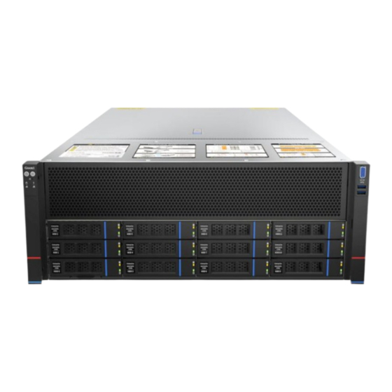
2.1.1 Appearance 12x3.5-inch hard drive configuration Figure 2-1 Name Name Left Ear Integrated Right Ear Integrated Assembly Assembly Front Panel Hard Drive Module Table 2-1 2.1.2 Indicator lights and buttons Figure 2-3 Indicator/button Indicator/button Gooxi Logo M.2 Hard Drive Activity... - Page 11 Status Indicator LED status description Logo Indicator/button Status description Gooxi logo Description of the power indicator light: Green (steady on): Indicates that the device has been powered on normally. Green (blinking): Indicates that the device is in standby. Green off: Indicates that the device is not powered on.
-
Page 12: Interface
2.1.3 Interface Interface location Figure 2-4 Name Name VGA Port USB3.0 Interface Table 2-3 Interface description Name Type Description Used to connect display terminals, such as VGA Port DB15 monitors or KVMs USB3.0 Used to connect USB devices Interface Table 2-4 2.2 Rear Panel... -
Page 13: Indicator Lights And Buttons
PCIe Rear Panel IO Board Power Module USB 3.0 Interface VGA Port Management Network Port Table 2-5 Note: The rear window of this product can be customized according to the needs. The above picture is for reference only, and the actual configuration shall prevail. -
Page 14: Processors
Figure 2-6 Name Name Power Module Indicator Light UID Button Management Network Port COM Port Connection Status Indicator Management Network Port Data Transmission Status Indicator Table 2-7 Description of Power Module Indicators Indicator light /button Status description Green (steady): Indicates normal input and output. Orange (steady): Indicates AC power cord unplugged or power module missing. -
Page 15: Memory
The processors configured in the same server must be of the same model. For specific optional system components, please consult Gooxi sales. The processor locations are shown in the diagram below: Figure 2-7 2.4 Memory 2.4.1 Memory slot location Developed based on the AMD EPYC Milan platform, it supports two AMD EPYC Milan series processors and is compatible with Rome series processors. -
Page 16: Memory Compatibility Information
Figure 2-8 2.4.2 Memory compatibility information Note: The same server must use the same model of DDR4 memory, and all memory must run at the same speed. Likewise, the velocity value is the lowest of the following. The memory speed supported by the specific CPU. ... -
Page 17: Storage
Figure 2-9 2.5 Storage 2.5.1 Hard drive configuration Configuration Description 2 NVMe SSDs SAS drives require an HBA 8 SATA/SAS HDDs/SSDs or RAID card 4 NVMe SSDs 12 NVMe SSDs Supports up to 6 GPUs Table 2-9 2.5.2 Hard drive serial number 12x3.5-inch hard drive configuration ... -
Page 18: Hard Drive Status Indicator
When configuring with 4 power modules, supports 3+1 or 2+2 redundancy. Power modules configured in the same server must be of the same model. For specific optional system components, please consult Gooxi sales. The power module locations are shown in the diagram below: ... -
Page 19: Fans
Figure 2-13 The device is equipped with two identical, hot-swappable power modules, which must supply power simultaneously for the product to function properly. 2.7 Fans The chassis supports 12*6506 fan modules. Hot-swappable support. Supports single fan failure. Supports variable fan speed. -
Page 20: Pcie Slot Location
2.8.1 PCIe slot location Figure 2-15 12-bay direct connection configuration: Provides slot 1 to slot 13, with a total of 13 PCIe slots. Slots 2 to 5 and slots 10 to 13 support dual-width GPUs, while slots 1, 7, and 8 support single-width PCIe cards. 2.8.2 PCIe slot description Pass-through PCIe slot configuration PCIe slot... -
Page 21: Pcba
full-height, full-length Dual-width, Slot 13 CPU0 PCIe 4.0 full-height, full-length Note: ◆PCIe x16 slots are backward compatible with PCIe x8, PCIe x4, and PCIe x1 cards. However, upward compatibility is not supported, meaning the slot bandwidth cannot be smaller than the PCIe card's bandwidth. ◆Full-height, full-length PCIe slots are backward compatible with half-height, half-length PCIe cards. -
Page 22: Hard Drive Backplane
Name PCIE 4.0 MCIO Connector Left Ear Board Connector 3、11 PCIe Pass-through Board P12V Power Connector Front Expansion I2C Connector NCSI Connector VGA Connector OCP NCSI Slimline 4i Slimline 4i USB3.0 Connector Right Ear Board Connector MCIO Connector Front Hard Drive Backplane Power Connector Fan Board Power Connector PCIe Riser Card Power Connector Fan Board Power Connector... - Page 23 Bottom surface Figure 2-18 Description Function Temperature-controlle 1、2、3、4 For 4-pin fan interfaces d Fan Sockets Provide SAS/SATA x4 SFF-8654 Slimline 5、6、7 interfaces for connecting to Connectors PCH or HBA/RAID cards Backplane power transmission Power Connector connector, used for 12V power transmission Mainly used for lighting control CPLD Chip...
-
Page 24: Installation Instructions
3. Installation Instructions 3.1 Chassis Top Cover Installation Step 1: Lift the slot at the opening position, push and lift it in the direction indicated by the diagram. Figure 3-1 3.2 Installation of Accessories 3.2.1 CPU installation Before starting the CPU installation, please read the following guidelines: ⚫... - Page 25 4.Using the handle on the CPU tray, insert the new CPU tray with the installed CPU back into the CPU rack. Note: Ensure that the CPU is oriented correctly in the CPU tray, aligning the triangle on the CPU with the top left corner of the CPU carrier. 5.Flip the CPU rack containing the installed CPU into the correct position over the CPU socket.
-
Page 26: Installation Of Heatsink
Figure (3-4) 3.2.2 Installation of heatsink Before starting to install the heatsink, please read the following guidelines: ⚫ Before installing the heatsink, please be sure to turn off the computer and unplug the power cord from the power outlet to prevent damage to the hardware. ⚫... -
Page 27: Installation Of Memory
Figure 3-5 Note: The pins on the motherboard are extremely fragile and can be easily damaged. To avoid damaging the motherboard, do not touch the processor or the contacts in the processor socket. 3.2.3 Installation of memory The 16 memory slots controlled by CPU 0 are: DIMM A1, A2, DIMM B1, B2, DIMM C1, C2, DIMM D1, D2, DIMM E1, E2, DIMM F1, F2, DIMM G1, G2, and DIMM H1, H2. -
Page 28: Gpu Card Installation
Note: For this motherboard, please use memory modules with the same CAS latency. It is recommended to use memory from the same manufacturer, with identical capacity and frequency. Additionally, please note: Within the same channel, the larger capacity memory must be installed in the first slot. - Page 29 Figure 3-10 Step 2: Fasten the inner rails to the sides of the chassis. Figure 3-11 Step 3: Install the outer rails on the cabinet brackets and secure the screws. Figure 3-12 Note: When installing the guide rail, align it with the U-mark, and push it into...
- Page 30 place until you hear a click sound. Secure it firmly using M5 screws. Step 4: Align the chassis with the inner rails installed with the outer rails for installation. Figure 3-13 Note: When you push the chassis forward, you will hear a snapping sound. If you can’t push it, you need to pull down the buckle of the inner rail to continue to push the chassis gently.
-
Page 31: Configuration Instructions
4. Configuration Instructions 4.1 Initial Configuration 4.1.1 Power on and start Before powering on, it is necessary to ensure that all configurations of the server are installed in accordance with the corresponding specifications and standards, and keep the server turned off but not unplugged from the power supply. - Page 32 Figure 4-1 State After G3 The menu options for setting the state after entering G3 status are: S0 State:Power on and start up directly S5 State:You need to press the Power button to turn on the power Default: S5 State Logging into the iBMC management interface allows for remote power on/off ...
-
Page 33: Initial Data
Figure 4-2 For detailed usage of BMC and BIOS, please refer to the corresponding user manual. 4.1.2 Initial data BMC default account: admin BMC default password: Gooxi@123. BMC default address: 192.168.100.1 BIOS Default Password: N/A 4.1.3 Configure BIOS Press the <DEL>... -
Page 34: Configure Bmc
Figure 4-3 The Main interface contains the basic information of the BIOS system, such as the BIOS version number, CPU model, memory capacity, and the system time can be set. For detailed instructions, please refer to the "BIOS User Manual". Navigation key description: ... - Page 35 enter the BMC IP address on the web page. Check the BMC IP address as follows: After the server is powered on, turn it on. Pay attention to the POST process when starting the server. In the lower left corner of the logo screen, the IP address is displayed.
- Page 36 port. The displayed information includes the current IP configuration method, BMC IP, subnet mask, MAC address, router IP, and router MAC. BMC Dedicated Management Channel Configuration Address source Configure the BMC IP address allocation mode, the menu options are: ...
- Page 37 will result in the options reverting to the "Unspecified" value. There is no need to configure the BMC IP during every startup process. When the "Configuration Address Source" option is set to "Unspecified," it will display the network parameters (IPv6) for the system's dedicated Ethernet port.
- Page 38 Figure 4-6 This page sets the IP address of the BMC management network port.
-
Page 39: Appendix
If the above steps do not resolve the issue, try replacing the monitor with a known working one to confirm if the original monitor is faulty. If the issue persists, please contact Gooxi's customer service department for resolution. Front Panel Indicator Lights Alarm Refer to the instructions in the manual to determine the specific alarm information indicated by the front panel lights and buttons. - Page 40 Set static or dynamic IP and ensure ping connectivity. If the web interface does not open, try using a newer version of Internet Explorer. If the problem is not resolved, please contact Gooxi’s customer service department for further assistance and resolution.
-
Page 41: Scrap Recycling
6. Scrap Recycling For environmental protection and resource reuse, we earnestly ask you to properly handle discarded server products. Before discarding the server, we recommend that you completely demagnetize the storage media, clear data, and physically destroy them to ensure that your personal data is not leaked.
Need help?
Do you have a question about the SYR4108G-G3 and is the answer not in the manual?
Questions and answers