
Related Manuals for Nady Systems UWS-1K Series


Summary of Contents for Nady Systems UWS-1K Series
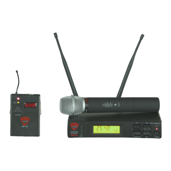
- Page 1 UWS-1K 1000 Channels PLL Frequency Synthesized UHF Wireless Microphone and Instrument System OWN E R ’S MA N UA L...
-
Page 2: Table Of Contents
UH-1K and UB-1K Transmitters ....................3 SYSTEM OPERATION ........................4 UWS-1K Receiver Buttons Function ..................4 Selecting the UWS-1K Receiver Group, Channel, and SQL Setting ........4 UH/UB-1K Transmitters Buttons Function ................4 Selecting the UH/UB-1K Transmitters Group and Channel Setting ........5 UWS-1K RECEIVER ..........................5 Rack-mounting the Receiver ....................5... -
Page 3: Introduction
UH-1K handheld microphone transmitters, and UWS-1K receiver. This manual will first explain the benefits of the UWS-1K and then will take you step by step on how to operate your new system. Each section will give you detailed information. Also, included in this manual are the system specifications and servicing information. -
Page 4: System Operation
20 seconds automatically. The UP-DOWN Rocker button (20) works only while setting the menu. At Power OFF the UWS-1K receiver will store the last settings entered and re-display them at Power ON. It can be repro- grammed to any new group/channel, and SQL level. -
Page 5: Selecting The Uh/Ub-1K Transmitters Group And Channel Setting
20 seconds after the transmitter is powered up. As soon as the transmitter LEDs light up indicat- ing Power ON, the Transfer Button (18) on the UWS-1K receiver must be pressed once while the MAIN MENU is being displayed. The Power LED (9) of the receiver will flash quickly indicating IR transmission to the transmitters of the Group and Channels selected on the receiver is in progress. -
Page 6: Adjusting The Mute (Rf Squelch)
UH-1K or UB-1K transmitter included with your system. (Please note: Only one transmitter can be used with one UWS-1K receiver. It is not possible too use two transmit- ters on the same frequency and mix the output of these transmitters into one wireless receiver.) - Page 7 UWS-1K RECEIVER 1. Rack ears (optional) 11. Group/Channel 2. Join pieces (optional) 12. RF level meter 3. Antennas 13. Diversity indicator 4. RF screw-on connectors 14. RF squelch (MUTE) 5. DC input jacks 15. AF LED display 6. XLR balanced output 16.
-
Page 8: Uh-1K Handheld Transmitter
(audio mute) mode and the previous program channel remains unchanged. After 20 seconds the IR LED (on both the UWS-1K and UH-1K) will turn off. (Note: The IR link is infrared light and thus works best when this data transfer is accomplished in a light-shielded or darker environment. -
Page 9: Ub-1K Bodypack Transmitter
UH-1K’s POWER button to unmute. To mute, press the Power/Mute button again. Adjust the vol- ume of the receiver as per section 12 (UWS-1K Receiver: Connecting Audio Output). [Note: Observe care in selecting P.A. volume, transmitter location and speaker placement so that acoustic feedback (howling or screeching) will be avoided.]... -
Page 10: Programming The Ub-1K With The Group/Channel Selected On The Receiver
When ready to transmit audio, press the UB-1K’s Power/Mute Button (32) to unmute. To mute, press the POWER button again. Adjust the volume of the receiver as per section 12 (UWS-1K Receiver: Connecting Audio Output) above. -
Page 11: Microphone Use (With Either A Lavalier Or Headworn Microphone)
UB-1K BODYPACK MICROPHONE TRANSMITTER unmute the transmitter audio. Adjust the volume on the receiver for one-to-one, unity gain with a hardwired cord or select up to an added 4-5dB boost by adjusting the receiver volume to maximum. (Note: The input level control is deactivated and not used when the UB-1K is in instrument mode. The level should be adjusted on the instrument as when using a hard-wired cord.) 22. -
Page 12: Cautions And Troubleshooting
(so field of 7 adjacent channel total—with channel used in the middle). If operating multiple UWS-1K systems simultaneously, repeat this procedure with every new channel being selected, with previously tuned systems all ON, both transmitters and receivers. -
Page 13: Tips
TIPS • For optimum operation with external antennas, low loss RF shielded cable should be used and the length of the cable should not exceed 3m. • The receiver antennas should be kept away from any metal surfaces whenever possible as they can reflect or shield from the incoming RF signal. -
Page 14: Specifications
SPECIFICATIONS SYSTEM SPECIFICATION Operating Frequency Range ..............760MHz-864MHz (3 bands) Freq. Synthesized ..............PLL system 1000 channels switchable 25kHz/step, frequency stability <0.005% Frequency Response ....................30Hz-18kHz -3dB Dynamic Range ......................... 120dB Harmonic Distortion ........................<0.5% Modulation ...................FM +/-25kHz normal, +/-75kHz max Operating Range ............. 250 feet normal, 500+feet max line-of-sight RECEIVER SPECIFICATIONS Receiver System ..........Dual conversion superheterodyne with True Diversity (2 complete receiver sections with optimum audio selected) -
Page 15: Frequency Plan
FREQUENCY PLAN Band-1 748.900-773.875MHz 25kHz per step (1000 Channels) U.S. Band-2 795.000-820.000MHz 25kHz per step (1000 Channels) U.S./ Europe Band-3 846.000-871.000MHz 25kHz per step (1000 Channels) Europe ACCESSORIES Part Number Description RMK-1K Single receiver rack mount kit RMK-1KX2 Dual (side-by-side) receiver rack mount kit IC-U1K Instrument cable for UB-1K transmitter, 4-pin mini-XLR to 1⁄4”... -
Page 16: Service Information
(U.S.) If you are experiencing operation problem with your system, check out the support page on the Nady website: www.nady.com for help and for contacting the Nady Service Department. Should your wireless System require service, you must contact the Nady Service Department at (510) 652-2411 for a Return Authorization (R/A) Number and a service quote (if out of warranty).
Need help?
Do you have a question about the UWS-1K Series and is the answer not in the manual?
Questions and answers