Table of Contents
Advertisement
Advertisement
Table of Contents

Related Manuals for Nady Systems U-41 QUAD


Summary of Contents for Nady Systems U-41 QUAD
- Page 1 U-41 QUAD Four Discrete Channel UHF Wireless Microphone System OW N ER ’S M ANUAL...
-
Page 2: Table Of Contents
WARRANTY ..........................15 INTRODUCTION Thank you for choosing the Nady U-41 QUAD wireless system, we know you will be very pleased with its performance and features. The Nady U-41 QUAD is a professional 4-channel UHF wireless system which offers the clearest, most natural sound available in wireless today. The Nady U-41 QUAD delivers four discrete channels in the 902-928MHz and 944-952MHz bands for interference-free performance in any application or locale. -
Page 3: System Features
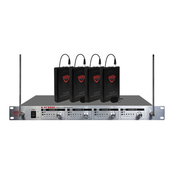
SYSTEM FEATURES U-41 QUAD Receiver • Four discrete UHF wireless receivers in a single rugged 19” 1U, all-metal rack mount housing • Back panel Balanced XLR mic level output, Unbalanced 1⁄4” jack line level sum output with separate volumes, and external adjustable mute control for each channel •... -
Page 4: Quad Receiver Operation Instruction
Install antennas by connecting the two AntennAs (1) included with your system to the two RF BnC ConneCtoRs (2) located on the left and right front of the U-41 QUAD receiver. The optimal positions of the antennas are 90 degrees from the receiver pointing up position. - Page 5 U-41 QUAD RECEIVER The U-41 QUAD also has a summed adjustable line level unbalanced output for all channels (MIX). To use, just plug an audio cable with a 1⁄4” mono plug into the MIX out and plug the other end to your amplifier or mixing board.
- Page 6 U-41 QUAD RECEIVER...
-
Page 7: Handheld Transmitter
If the fixed level XlR oUtPUts (10) are used, the volume level of each receiver should be adjusted by the mixer to which the U-41 QUAD UHF receiver is connected. The microphone is ready to use. The corresponding TX LED indicator on the U-41 QUAD UHF receiver should now be lit. -
Page 8: Bodypack Transmitter
UH-4 HANDHELD TRANSMITTER UB-4 BODYPACK TRANSMITTER transmitters set up The UB-4 transmitter requires a single 9V battery to operate. To open the battery compartment, snap open the BAtteRy dooR CoveR (21), exposing the BAtteRy holdeR (22). Insert a fresh 9V battery according to the correct polarity as indicated on the transmitter body. Snap the cover back onto the bodypack. - Page 9 UB-4 BODYPACK TRANSMITTER The UB-4 is equipped with two InPUt seleCtoR swItChes (27) located under the cover on the circuit board for selecting the type of audio input you will be supplying to the transmitter. Select from the choice of three positions: INSTRUMENT (for guitar, bass, etc.)/ HEADWORN MIC/ LAVALIER MIC.
- Page 10 UB-4 BODYPACK TRANSMITTER InPUt seleCtoR swItChes Instrument Headworn Lavalier Opening Battery Compartment...
-
Page 11: Cautions And Troubleshooting
CAUTIONS AND TROUBLESHOOTING Feedback Observe care in selecting P.A. volume, transmitter location and speaker placement so that the acoustic feedback (howling and screeching) will be avoided. Please also note the pickup pattern characteristics of the microphone selected. Omni directional mics pick up sound equally from all direction, and are prone to feedback if not used carefully. -
Page 12: Tips
TIPS • The receiver antennas should be kept away from any metal surface. • If the Volume Control of the receiver is set too high, it may over-drive the input of the mixer, causing distortion. Conversely, if the output is set too low, the overall signal to noise ratio of the system may be reduced. -
Page 13: Specifications
SPECIFICATIONS oveRAll system sPeCIFICAtIons Frequency Response .....................30Hz-18kHz, -3dB Dynamic Range .........................120dB Harmonic Distortion ..................... <0.5% THD, normal RF Carrier Frequencies ...............Factory installed channels between 902-928MHz and 944-952MHz Frequency stability ................+/-0.005% Crystal Controlled Modulation ................. FM +/-20kHz normal, +/-50kHz maximum TSQ Frequency ........................32.768kHz Operating Range .............250 feet normal, 500+feet max line of sight ReCeIveR sPeCIFICAtIons Controls .............. -
Page 14: Service Information
If your unit is out of warranty, please enclose a cashier’s check or money order (or pay by credit card) per instructions by the Nady Service Department. Ship your unit prepaid to: Nady Systems, Service Department, 6701 Shellmound Street, Emeryville, CA 94608. Include a brief description of the problem you are experiencing. -
Page 15: Warranty
Nady Systems, Inc. for repair. The warranty is null and void if any Nady serial number has been removed or defaced. - Page 16 6701 Shellmound Street | Emeryville, CA USA 94608 T 510.652.2411 | F 510.652.5075 | www.nady.com...
Need help?
Do you have a question about the U-41 QUAD and is the answer not in the manual?
Questions and answers